Baumer LBFI Operating instructions

Type
Operating instructions

This manual is also suitable for

Level measurement
CleverLevel
®
LBFH/I
Point level detection – hygienic/industrial
EN Operating Instructions 3
DE Betriebsanleitung 17
FR Manuel de mise en service 31
Operating Instructions
Level measurement
CleverLevel
®
LBFH/I
Point level detection – hygienic/industrial
Type plate / Typenschild
Type
Type of sensor
Matr.
Material number
In
Input voltage and
power consumption
Out
PNP, NPN, digital, customer-specic
Maximum external load
Tamb
Ambient temperature
S/N
Serial number
Date
Date of manufacture
Do not dispose of in household waste
Conformity with EU directives
Permissions, customer-specic
Version
Sensortyp
Matr.
Materialnummer
In
Eingangsspannung und Stromverbrauch
Out
PNP, NPN, digital, kundenspezisch
Maximale externe Last
Tamb
Umgebungstemperatur
S/N
Seriennummer
Date
Herstellungsdatum
Nicht im Hausmüll entsorgen
Konformität mit EU-Richtlinien
Zulassungen, kundenspezisch
Version
Type de capteur
Matr.
f. mat.
In
Tension d'entrée et consommation
électrique
Out
PNP, NPN, digital, spécique au client
Charge externe maximale
Tamb
Température ambiante
S/N
Numéro de série
Date
Date de fabrication
Ne pas jeter avec les ordures
ménagères
Conformité avec les directives
européennes
Autorisations, selon le client
2 / 48
www.baumer.com
Operating Instructions
Level measurement
CleverLevel
®
LBFH/I
Point level detection – hygienic/industrial
Table of contents
1. Safety .......................................................... 3
2. Construction and function ........................... 3
3. Symbols in warning signs ............................ 4
4. Transport and storage ................................. 4
5. Assembly ..................................................... 4
6. Electrical connection ................................... 7
7. Electrical connection in explosion hazard
areas ........................................................... 8
8. Conguration ............................................. 10
9.
Troubleshooting ..........................................12
10.
Cleaning, maintenance and repair..............12
11.
Disposal .....................................................12
12. Accessories ................................................12
13. Technical data ............................................12
14. Conguration overview ...............................13
1. Safety
Intended use
The sensor must be used solely for the level
detection of liquids and solids with a dielectric
constant of at least 1.5.
The sensor must only be used for media against
which the housing material and sensor tip are
resistant.
Staff qualification
Only use staff who are trained for the activities
described. This applies in particular to assembly,
installation, conguration and troubleshooting.
Make sure that the staff have read and understood
these instructions.
Technical condition
Only use sensor in perfect technical condition.
Only use Baumer accessories.
Baumer will accept no liability for other
manufacturers’ accessories.
Risk of burns from hot media
During operation the sensor housing may warm
up to over 50 ºC. When working with hot media
provide protection against burns.
2. Construction and function
1 2 3
4
Fig. 1. Construction
f
L
C
µC
Fig. 2. Function
1 Sensor tip
2 LED
3 Connection with M12 plug
4 qTeach detector
An electrode integrated into the sensor tip forms
a capacitor with the environment. The medium
determines the capacity value depending on
its dielectric constant (DC values). A resonant
circuit occurs together with a coil in the sensor
electronics. Depending on the resonance
frequency measured and the programmable trigger
threshold, the switch signal is activated.
www.baumer.com
3 / 48
Operating Instructions
Level measurement
CleverLevel
®
LBFH/I
Point level detection – hygienic/industrial
3. Symbols in warning signs
Symbol Warning term Explanation
DANGER
In situations which cause death or serious injuries.
WARNING
In situations which can cause death or serious injuries.
CAUTION
In situations which can cause light or medium injuries.
ATTENTION
For material damage
4. Transport and storage
f
Check packaging and sensor for damage.
f
In the event of damage: Do not use sensor.
f
Store sensor where it will be secure against
shock.
Storage temperature: -40 ... +85 °C
Relative humidity: < 98 %
5. Assembly
2
4
1
3
4
4
Fig. 3. Mounting options
1 Overll protection
2 Limit level, max.
3 Limit level, min.
4 Run-dry protection
The sensor can be mounted on any point in the
vessel.
A sensor mounted at the top of the vessel (1)
ensures against overlling. Sensors attached
further down detect a maximum (2) or minimum (3)
limit level. A sensor attached at the bottom or on
the outfeed pipe (4) can protect a connected pump
against dry running.
4 / 48
www.baumer.com
If the sensor is mounted in a pipe, it is
recommended to use window trigger as the trigger
function. The adaptive trigger can have limited
functionality if it is mounted in a pipe.
Operating Instructions
Level measurement
CleverLevel
®
LBFH/I
Point level detection – hygienic/industrial
5.1 LBFI mounting
DANGER
Risk of injury from hazardous medium
f
Wear protective equipment for hazardous media (e.g. acids, alkaline solutions).
f
Empty vessel and pipelines before mounting.
PTFE
1
2
LBFI with the following process connections:
G 1/2 A ISO 228-1 (BCID G07)
1/2-14 NPT (BCID N02)
9 Vessel and pipelines are free of media.
f
Seal thread on sensor with Teon tape (PTFE).
f
Screw in sensor.
G 1/2 A tightening torque: 30 Nm max.
NPT tightening torque: 20 Nm max.
LBFI with the following process connections:
G 1/2 A ISO 228-1 (BCID G07) with industrial
weld-in sleeve for universal use, Ø 30 x 26
(ZPW1-711, ZPW1-721)
G 1/2 A hygienic (BCID A03) with weld-in sleeve
or adapter from Baumer
For these process connections, do not seal with
Teon tape (PTFE) or elastomer.
9 Vessel and pipelines are free of media.
9 Adapter or weld-in sleeve are mounted free of
dead space.
f
Screw in sensor.
Tightening torque: 15 ... 20 Nm
www.baumer.com
5 / 48
Operating Instructions
Level measurement
CleverLevel
®
LBFH/I
Point level detection – hygienic/industrial
5.2 LBFH mounting
WARNING
Danger to health from contaminated medium
f
Only use weld-in sleeves or adapters from Baumer.
f
Do not seal process connections with Teon tape (PTFE) or elastomer.
f
Welding work must only be carried out by welders trained in the area of hygiene.
LBFH with the following process connection:
G 1/2 A hygienic, BCID A03
9 Weld-in sleeve or adapter are hygienically
mounted and are internally ush.
9 Weld seams are smoothed out to Ra < 0.8 µm.
9 Leakage hole points downwards.
f
Screw in sensor.
Tightening torque: 15 ... 20 Nm
Example of mounting with weld-in sleeve ZPW3-321
1
1
1
2
1 ZPW3-321
2 Leakage hole
Example of mounting with weld-in sleeve ZPW3-326 or ZPW3-327
170°
190°
6 / 48
www.baumer.com
Operating Instructions
Level measurement
CleverLevel
®
LBFH/I
Point level detection – hygienic/industrial
The EHEDG certicate is only valid in connection with the appropriate installation parts.
These are marked with the "EHEDG Certied" logo.
The 3-A Sanitary Standard requirements are only met with the appropriate installation parts.
These are mar
ked with the 3-A logo.
Approved for explosion hazard areas when installed as specied.
Approved by Underwriter Laboratories (UL) for use in the USA and Canada as an industrial
control device.
6. Electrical connection
9 A voltage supply of 8 V to 36 V DC is provided.
f
Switch off supply voltage.
f
Connect sensor in accordance with the pin
assignment.
Terminal assignment
1
2
43
Output type Equivalent circuit with IO-Link Function M12, 4 pin
PNP
+ Vs 1
SW1 4
SW2 2
GND (0 V) 3
NPN
+ Vs 1
SW1 4
SW2 2
GND (0 V) 3
Digital (push-
pull)
+ Vs 1
SW1 4
SW2 2
GND (0 V) 3
www.baumer.com
7 / 48
WHG
WHG certified for leakage and overfill protection. All documentation must be available at the
place of use and can be found on the product page on www.baumer.com
For more information about approvals and certication, please see the product page on www.baumer.com.
5.3 Approvals
Operating Instructions
Level measurement
CleverLevel
®
LBFH/I
Point level detection – hygienic/industrial
7. Electrical connection in explosion hazard areas
Depending on the variant, the LBFH/I is approved for most explosion hazard areas.
DANGER
Risk of fatal accident due to a wrongly connected sensor
f
In explosive gas atmospheres of zone 0 or 1, use Baumer isolation barriers or Zener barriers.
f
In explosive dust atmospheres, use insulated cable to IP67.
f
Allow only persons trained in explosion protection to perform the installation.
f
Never use FlexProgrammer or IO-Link Master conguration tools in explosion hazard areas.
7.1 Explosive gas atmospheres zone 0 and 1
The LBFH/I can be used in explosion hazard areas of zone 0 or zone 1. Sensors can use Baumer isolation
barriers which are easy to install or use Zener barriers.
Approval for LBFx.xx.xxx.xxxxxx.x.4xxx.x: ATEX II 1G Ex ia IIC T4 Ga
and ATEX II 1D Ex ta IIIC T100 °C Da (TÜV 17 ATEX 188894 X)
LBFx.xx.xxx.xxxxxx.x.4xxx.x and additional
dust atmospheres:
f
Use insulated cable to IP67.
f
Secure cables with external strain relief at a
distance 5 centimeters from the sensor.
All LBFH/I in zone 0 and zone 1
f
Use PROFSI3-B25100-ALG-LS isolation
barriers for the connection.
– or –
Use Zener barriers.
f
Comply with the following temperatures,
connection values and circuit diagram.
ATEX II 1G Ex ia IIC T4 Ga
Highest values for se-
lection of barriers
Ui: 30 V DC
Ii: 100 mA
Pi: 0,75 W
Internal capacitance Ci: 63 nF
Internal inductance Li: 617 µH
Temperature class T1…T4:
40 < Tamb < 85 °C
Protection class for
cable accessories
IP67
1
3
4/2
+
SW1/SW2
Function M12-A
4-pin
+ Vs 1
GND (0V) 3
SW1/SW2 4/2
DANGER
Risk of fatal accident due to failing communication with the sensor
IO-Link communication is not possible when a barrier is installed.
f
Do not use IO-Link communication together with a barrier.
8 / 48
www.baumer.com
Operating Instructions
Level measurement
CleverLevel
®
LBFH/I
Point level detection – hygienic/industrial
DANGER
Risk of fatal accident if installation requirements are ignored
Correct gas and dust protection can only be achieved by meeting their installation requirements.
f
Make sure that all requirements are met and that sensor and installation have a valid approval for
their specic explosive atmosphere.
f
In an explosive gas atmosphere, always use the sensor with a barrier.
7.2 Explosive dust atmospheres zones 20, 21 and 22
The LBFH/I can be used in explosion hazard areas of zone 20, 21 and 22.
Approval for LBFx.xx.xxx.xxxxxx.x.4xxx.x: ATEX II 1D Ex ta IIIC T100 °C Da (TÜV 17 ATEX 188894 X)
LBFx.xx.xxx.xxxxxx.x.4xxx.x: ATEX II 1D Ex ta IIIC T100 °C Da
f
Use insulated cable to IP67.
f
Secure cables with external strain relief at a
distance 5 centimeters from the sensor.
f
Comply with the following temperatures,
connection values and circuit diagram.
Voltage supply range 30 V DC max.
Temperature class T100°C:
40 < Tamb < 85 °C
Surface temperature 100 °C max.
Protection class fpr cable
accessories
IP67
1
3
4/2
+
SW1/SW2
Function M12-A
4 pin
+ Vs 1
GND (0V) 3
SW1/SW2 4/2
www.baumer.com
9 / 48
7.3 Explosive gas atmospheres zone 2
The LBFH/I can be used in explosion hazard areas of zone 2.
Approval for LBFx.xx.xxx.xxxxxx.x.3xxx.x: ATEX II 3G Ex nA IIC T4 Gc (TÜV 17 ATEX 188895 X)
LBFx.xx.xxx.xxxxxx.x.3xxx.x: ATEX II 3G Ex nA IIC T4 Gc
f
Comply with the following temperatures,
connection values and circuit diagram
Voltage supply range Un: 30 V DC max.
Temperature class T1…T4:
40 < Tamb < 85 °C
1
3
4/2
+
SW1/SW2
Function M12-A
4 pin
+ Vs 1
GND (0V) 3
SW1/SW2 4/2
Operating Instructions
Level measurement
CleverLevel
®
LBFH/I
Point level detection – hygienic/industrial
8. Conguration
The sensor can be congured either via qTeach,
remote teach, FlexProgrammer or IO-Link. If
formation of foam or adhesion of media have to be
detected, a conguration with the FlexProgrammer
will be necessary.
If for both switch outputs different switch points or
media have to be congured, a conguration with
FlexProgrammer or qTeach is also necessary.
Configuring with qTeach (Standard version)
Via qTeach, the switch points SW1 and SW2 can
be congured independently. Switch output SW1
is NO (normally opened) and switch output SW2 is
NC (normally closed).
Conguration is only possible during the rst
5 minutes after connecting the voltage supply.
After that, qTeach will be locked.
Note: For a graphical overview of the conguration
procedure refer to “14.5 Conguration procedure
with qTeach” on page 16.
9 Sensor is connected.
f
Hold screwdriver or other metal object on the
qTeach detector.
The LED is blinking magenta at 1 Hz for
3 seconds. For selecting the switch the LED
alternates between yellow and blue in 2 second
intervals.
f
When the LED has the color of the desired
switch, remove the screwdirver or metal object
from the qTeach detector to select the according
switch:
SW1: yellow
SW2: blue
The LED is blinking in the selected color at 0.5 Hz.
f
Put the sensor tip into the media and touch the
qTeach area.
The LED ashes in the selected color while the
teaching process is running.
10 / 48
www.baumer.com
For selecting the switching window the LED
alternates between green, cyan and white in
2 second intervals.
f
Hold screwdriver or other metal object on the
qTeach detector.
f
When the LED has the color of the desired
switching window, remove the screwdriver or
metal object from the qTeach detector to select
the according switching window:
Switching window ±12%, hysteresis 4%: green
Switching window ±6%, hysteresis 2%: cyan
Switching window ±3%, hysteresis 1%: white
The conguration is complete and the changes are
saved.
If the DC value of the media is too close to air, the
most narrow switching window has to be selected.
If the LED ashes red (indicating an error) or
if the conguration time of 5 minutes has been
exceeded, no changes are saved.
f
To restart the conguration disconnect and
reconnect the voltage supply.
Conguration via qTeach is enabled in the factory
settings and can be disabled by the user.
Operating Instructions
Level measurement
CleverLevel
®
LBFH/I
Point level detection – hygienic/industrial
Conguring via remote teach
Sensors that are built into places hard to access
can be congured via remote teach easily and
without any other help. The switch points SW1
and SW2 can be congured independently. Switch
output SW1 is NO (normally opened) and switch
output SW2 is NC (normally closed).
9 The remote teach function has been activated
with FlexProgrammer before the integration of
the sensor (see FlexProgrammer instructions).
f
Short-circuit switch output SW1 for more than
1 second with GND (0 V).
The LED ashes magenta.
f
Continue as described in the qTeach procedure.
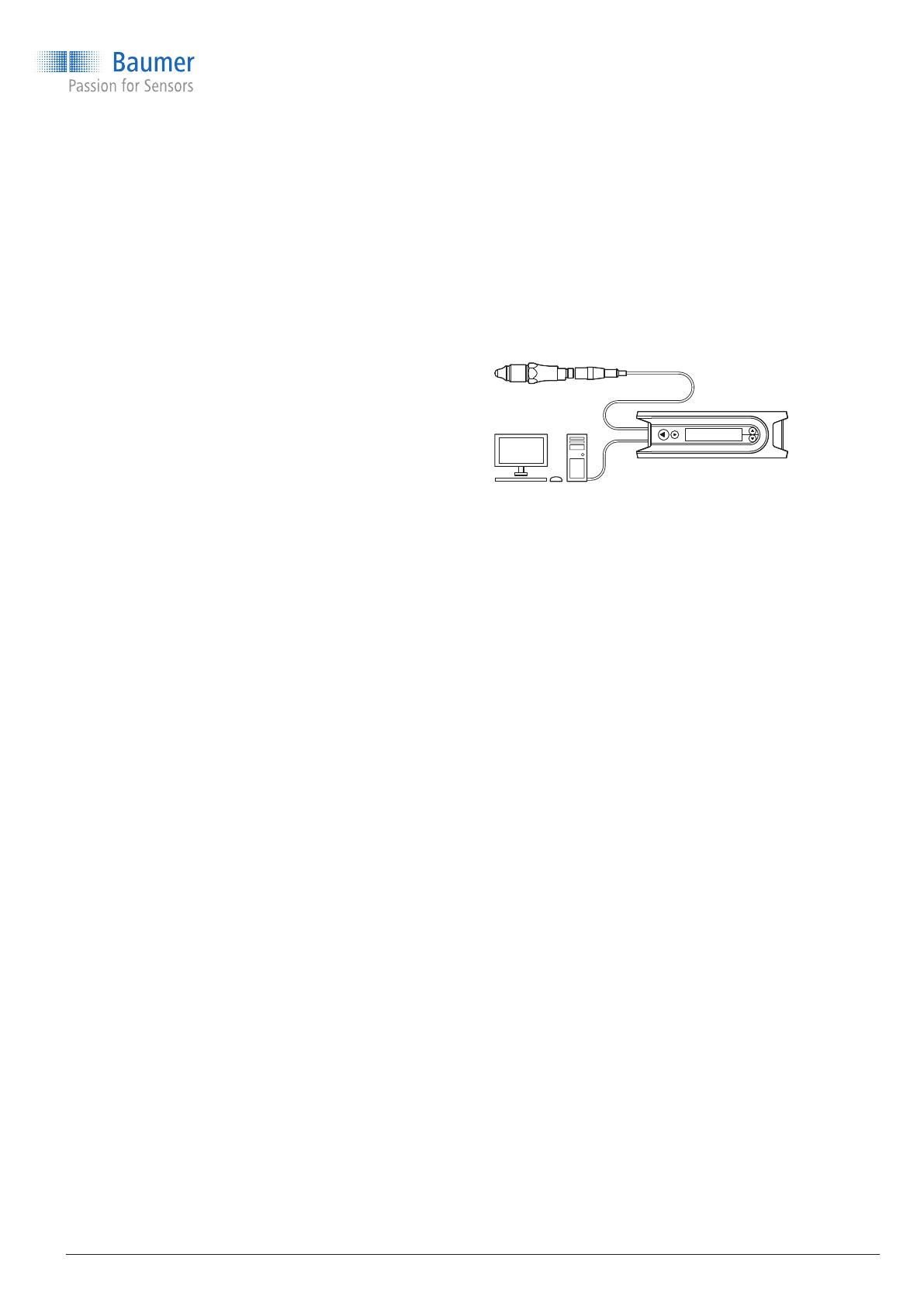
Conguring with F
lexProgrammer and PC
Switch points and damping of both switch outputs
can be set as desired with FlexProgrammer.
f
Connect FlexProgrammer to sensor.
f
Connect FlexProgrammer to PC and set
parameters (see FlexProgrammer instructions).
Conguring with IO-Link Master
Switch points, hysteresis, damping, output mode,
etc. can be congured via IO-Link with an IO-Link
Master.
f
Connect IO-Link Master to sensor
f
Connect IO-Link to PC and set parameters.
A detailed description of the parameter and
process data for the IODD can be found on www.
baumer.com in the products separate download
area.
www.baumer.com
11 / 48
Step 1: Selecting the switch
9 Sensor is powered up.
f
Hold a screwdriver or other metal object on the
qTeach detector.
The LED rapidly blinks magenta. The LED
alternates between yellow, cyan and orange in
3 second intervals.
f
When the LED has the color assigned to the
desired switch, remove the screwdriver from the
qTeach area:

Yellow: SW1

Cyan: SW2

Orange: Factory setting
The LED slowly blinks in the selected color.
Configuration via qTeach (Adaptive version)
Via qTeach, the different trigger types can be set
for SW1 and SW2. The switch logic is normally
open (NO) for both SW1 and SW2.
For a graphical overview of the conguration
procedure, refer to “14.4 qTeach conguration
procedure” on page 15.
Note: Conguration is only possible during the rst
5 minutes after connecting the sensor to the power
supply. After that, qTeach is locked.
Step 2: Selecting the trigger type
f
For the switch selected in step 1, select the
trigger type by holding the screwdriver on the
qTeach area again. When the desired trigger type
appears, remove the screwdriver:

White: Window trigger

Green: Adaptive trigger
If the LED ashes red, an error has occured and the
changes are not saved.
f
To restart the conguration, disconnect and
reconnect the sensor to the power supply.
Conguration via qTeach is enabled in the factory
settings and can be disabled by the user.
Operating Instructions
Level measurement
CleverLevel
®
LBFH/I
Point level detection – hygienic/industrial
9.
Troubleshooting
Fault Cause Action
LED does not light up Sensor not correctly connected
f
Check plug and power supply.
Red LED indicator light Short circuit
f
Remedy short circuit.
Unsuitable media characteristics
f
Check signal quality with
FlexProgrammer.
LED ashes red Device error
f
Dismount and return sensor.
10.
Cleaning, maintenance and repair
Cleaning
f
Clean, disinfect or sterilize sensor as needed
(CIP/SIP).
Maintenance
Regular maintenance is not required.
Repair
Do not repair the sensor yourself.
f
Send damaged sensor to Baumer.
11.
Disposal
f
Do not dispose of in household
waste.
f
Separate materials and dispose
of in compliance with nationally
applicable regulations.
12 / 48
www.baumer.com
12.
Accessories
For adapter and other accessories see www.baumer.com.
13.
Technical data
FeaturesEnvironmental conditions
Operating temperature
range

-40 ... -85 °C Repeatability

± 1 mm
Storage temperature range

-40 ... -85 °C Hysteresis

± 1 mm
Ambient humidity

< 98 % RH,
condensing
Response time

0.04 s
Protection class

IP67

IP69K (with
appropriate cable)
Damping

0.1 ... 10.0 s (adjustable)
Oscillations (sinusoidal)
(EN 60068-2-6)

1.6 mm p-p
(2 ... 25 Hz),
4 g (25 ...100 Hz),
1 octave / min.
Operating Instructions
Level measurement
CleverLevel
®
LBFH/I
Point level detection – hygienic/industrial
Power supply Output signal
Voltage supply range
8 ... 36 V DC Output type
PNP
NPN
Digital (push-pull)
Reverse polarity protec-
tion
yes Current load
100 mA max.
Current consumption
(without load)

25 mA type.,
40 mA max.
Short circuit protec-
tion
yes
Power-up time
< 2 s Voltage drop
PNP: (+Vs -0.5 V) ± 0.2 V,
Rload = 10 kΩ
NPN: (+0.5 V) ± 0.5 V,
Rload = 10 kΩ
Leakage current
± 100 μA max.
Switching logic
Normally open (NO), active
low
Normally closed (NC), high
enabled
www.baumer.com
13 / 48
Process conditions
Type Process connection BCID Process
temperature
continuous
[°C]
Process
pressure
[bar]
Process
temperature
t < 1 h
[°C]
Process
pressure
t < 1 h
[bar]
T
amb < 50 °C Tamb < 50 °C
LBFI G 1/2 A ISO 228-1 -1 ... 100
LBFI 1/2-14 NPT -1 ... 100
LBFH/I G1/2 A hygienic
G07 -40 ... 115
N02 -40 ... 115
A03 -40 ... 115
-1 ... 100 135
-1 ... 100 135
-1 … 10 135 -1 … 5
14. Configuration overview
14.1 Adaptive trigger
The adaptive trigger is a plug-and-play solution.
With the adaptive trigger, manual sensor
conguration is not required, since the trigger
will automatically congure the output signal to
react to a new medium. The adaptive trigger is
very useful for applications with sticky media or
for applications where the medium is changed
frequently.
Normally, it is not necessary to congure the
adaptive trigger, but if the advanced setup is
enabled, it is possible to dene low and high
set points for the adaptive trigger window and a
damping. The steady detection function ensures
that the input signal is steady for 1 second before
the switch output reacts. If the steady detection
function is inactive, the switch output will react
immediately to each input change.
LBFI G1/2 A hygienic,
length 82 mm
-1 ... 100
-1 ... 100 135
A03 -40 ... 115
Operating Instructions
Level measurement
CleverLevel
®
LBFH/I
Point level detection – hygienic/industrial
BU YE GN
BU = blue: SW2 active
YE = yellow: SW1 active
GN = green: Both switch outputs inactive.
14 / 48
www.baumer.com
14.3 LED factory settings
LED function (Standard version)
SW1*
SW2* LED indicator
0 0

Green
1 0

Yellow
0 1

Blue
1 1

Blue
Error Error

Flashing red
Short circuit Short circuit

Red
*1 = active, 0 = inactive
Color examples
To ensure a fully functional adaptive trigger, the
following conditions have to be fulfilled:

The sensor has to be in air during startup.

The input signal has to be steady.

The difference between the value for untriggered
and the value for triggered must be more than
3 %.

If a new medium with a DC value lower than
the previously congured DC value has to be
detected, the sensor tip should be cleaned before
the new medium is lled in the tank or pipe.
For more information, refer to the HELP menu in
FlexProgram.
Adaptive trigger – Output setup
SW1 (NO) / SW2 (NO) Factory setting
Disabled
0 %
100 %
0 ms
Advanced setup
Set point low
Set point high
Damping
Steady detection Active
14.2 Window trigger
The window trigger is used to cause a sensor switch to react within a specic range, for example, in order
to isolate a specic medium. The switching window can be congured within a range from 0 … 100 %. The
window trigger is recommended for detecting and separating different layers, for example oil from water or
foam from beer.
Sweep Range (%)
Signal
(%)
1000
0 02 05 08100
1 2 3 4
II IIII
1
2
3
4
Good conductive medium
Adhesion from good conductive adhesive
medium
Oily medium
Air
Conguration example for a vessel that can be
lled with either a good conductive adhesive
medium (e.g. fruit preparation) or with an oily
medium (e.g. chocolate mix).
Switch windows I and II in this example are set to
achieve the following goals:

to detect the fruit preparation (1)

to exclude adhesion from fruit preparation (2)

to identify the chocolate mixture (3)
For more information, refer to the HELP menu in
FlexProgram.
Window trigger – Output setup
SW1 (NO) / SW2 (NC)
Factory setting
0 %
75.3 %
2.4 %
Switch window, min.
Switch window, max.
Switch window, hysteresis
Damping 0.1 s
Operating Instructions
Level measurement
CleverLevel
®
LBFH/I
Point level detection – hygienic/industrial
www.baumer.com
15 / 48
LED function (Adaptive version)
SW1*
SW2* LED indicator
0 0

Green
1 0

Yellow
0 1
Cyan
1 1

Blue
Error Error

Flashing red
Short circuit Short circuit

Red
*1 = active, 0 = inactive
Color examples
YE GN
CY BU

YE = SW1 active

CY = SW2 is active

BU = Both SW1 and SW2 are active

GN = Both SW1 and SW2 are inactive
14.4 Configuration procedure with qTeach (Adaptive version)
A switch is selected by holding the screwdriver on
the qTeach area and removing it when the LED
displays the color assigned to the switch:

Yellow: SW1

Cyan: SW2

Orange: Factory setting
The trigger type for the selected switch can be
chosen by holding the screwdriver on the qTeach
area and removing it when the desired trigger type
is displayed:

White: Window trigger

Green: Adaptive trigger
+ 3 s
Step 2: Selecting the trigger type
Step 1: Selecting the switch
+3 s
+3 s
5 s
Operating Instructions
Level measurement
CleverLevel
®
LBFH/I
Point level detection – hygienic/industrial
14.5 Configuration procedure with qTeach (Standard version)
1 Ready for teaching. Immerse the sensor in the medium.
2 Choose switching window: Hold the tool until the desired switching window appears.
3 No medium
4 With medium
16 / 48
www.baumer.com
Operating Instructions
Level measurement
CleverLevel
®
LBFH/I
Point level detection – hygienic/industrial
46 / 48
www.baumer.com
Operating Instructions
Level measurement
CleverLevel
®
LBFH/I
Point level detection – hygienic/industrial
www.baumer.com
47 / 48
2020-05-15: 11173033 06
Baumer A/S
Runetoften 19
8210 Aarhus V
Denmark
Phone: +45 8931 7611
Fax: +45 8931 7610
Mail: sales.cc-lct@baumer.com
Level measurement
CleverLevel
®
LBFH/I
Point level detection – hygienic/industrial
  • Page 1 1
  • Page 2 2
  • Page 3 3
  • Page 4 4
  • Page 5 5
  • Page 6 6
  • Page 7 7
  • Page 8 8
  • Page 9 9
  • Page 10 10
  • Page 11 11
  • Page 12 12
  • Page 13 13
  • Page 14 14
  • Page 15 15
  • Page 16 16
  • Page 17 17
  • Page 18 18
  • Page 19 19
  • Page 20 20
  • Page 21 21
  • Page 22 22
  • Page 23 23
  • Page 24 24
  • Page 25 25
  • Page 26 26
  • Page 27 27
  • Page 28 28
  • Page 29 29
  • Page 30 30
  • Page 31 31
  • Page 32 32
  • Page 33 33
  • Page 34 34
  • Page 35 35
  • Page 36 36
  • Page 37 37
  • Page 38 38
  • Page 39 39
  • Page 40 40
  • Page 41 41
  • Page 42 42
  • Page 43 43
  • Page 44 44
  • Page 45 45
  • Page 46 46
  • Page 47 47
  • Page 48 48

Baumer LBFI Operating instructions

Type
Operating instructions
This manual is also suitable for

Ask a question and I''ll find the answer in the document

Finding information in a document is now easier with AI

in other languages