
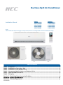
Ductless Split Air Conditioner
Installation Manual
Step 1 - Preparation ...................................................................................................................... 2
Step 2 - Installation of the Indoor Unit ........................................................................................... 3
Step 3 - Installation of the Outdoor Unit ........................................................................................ 4
Step 4 - Interconnecting the Indoor and Outdoor Units ................................................................. 5
Step 5 - Leak Test and Evacuation .................................................................................................. 6
Step 6 - Charging ........................................................................................................................... 7
Section 7 - Explaining Operation to the End User ........................................................................... 8
.................................................................................................. 8
Section 9 - S
0010590560
eacoast Application ................................................................................................... 8
Table of Contents
Indoor
AS09TB1HRH
AS12TB1HRH
AS15TD1HRE
AS18TD1HRE
AS24TE1HRE
Outdoor
1U09BU1ERH
1U12BU1ERH
1U15RU1ERE
1U18RU1ERE
1U24SU1ERE
Note:
3OHDVHPDNHVXUHWKHSRZHUVXSSO\FRUUHFWO\DWƪUVWNNYROWDJHZKLOHNNNYROWDJH

INSTALLATION
PAGE 2
ENGLISH
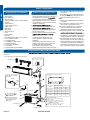
Step 1 - Preparation
Required Tools for Installation
Procedure for Selecting the Location
Ţ Drill
Ţ :LUHSnipper
Ţ +ROH6aZŞ
Ţ VDFXXPSXPS
Ţ Soap-and-wDWHUVROXWLRQRUJDVOHDkDJH
detector
Ţ TRUTXHZUHQFK
Ţ PPPPPP
Ţ TXELQJFXtter
Ţ FODULQJtool
Ţ RazRUNQLIH
Ţ 0HDVXULQJWDSH
Ţ Level
Ţ MicrRQJDXJH
Ţ NitrRJHQ
Ţ Mini-SSOLW$'$GDSWHUŞtRŞ
Ţ $1RQDGKHVLYHTape
Ţ %$GKHVLYHTape
Ţ &6DGGOH/.SZLWKVFUewV
Ţ '(OHFWULFDOZLULQJ
Ţ ('rDLQKRVH,QFOXGHG
Ţ ),QVXODWLRQ
Ţ *PLSLQJKROHcoYHU,QFOXGHG
WKDQIWawa\GHSHQGLQJRQrDGLRwaYH
conditionV
Ţ6LQFHGrDLQ
RXWRIWKHRXWGRRUXQLW
GRQoWSODFHDn\WKLQJXQGHUWKHXQLWWKDW
PXVWEHNHSWawa\IrRPPRLVture.
Note:
&DQQoWEHLQVWDOOHGKDQJLQJIrRPFHLOLQJ
RUVWDFNHG
,ILQVWDOOLQJRQDKLJKSODFHVXFKDVDrooI
ZLWKDIHQFHRUJXDUGrDLODrRXQGLW
,IWKHUHLVDSoWHQWLDOIRUDFFXPXODWHG
VQoZtREORFNWKHDLULQOHWRUKHDWex-
FKDQJHrLQVWDOOWKHXQLWRQDKLJKHUEDVH
R$UHIULJHrDQWLVDVDIHQRQto[LFDQG
WKHUHLVDcRQFHUQDERXWDGDQJHrRXVOeYHO
RIUHIULJHrDQWconcentrDWLRQLQWKHFDVHRI
UHIULJHrDQWOHDkDJHDGGextrDYHQWLODWLRQ
$vRLGLQVWDOOLQJWKHRXWGRRUXQLWZKHUH
corrRVLYHJDVHVVXFKDVVXOIXUoxideVDP
PRQLDDQGVXOIXrRXVJDVDUHSrRGXFHG,I
unavRLGDEOHcRQVXOWZLWKDQLQVWDOODWLRQ
VSHFLDOLVWaboutXVLQJacorrRVLRQSrRRIRU
DQWLUXVWDGGLWLYHtRSroWHFWWKHXQLWcoilV
Ţ &KRRVHDSODFHVROLGHQRXJKtREHDUWKH
ZHLJKWDQGYLErDWLRQRIWKHXQLWDQGZKHUH
WKHRSHrDWLRQQRLVHZLOOnot
Ţ &KRRVHDORFDWLRQZKHUHWKHKoWDLU
GLVFKDUJHGIrRPWKHXQLWRUWKHRSHrDWLRQ
QRLVHDQGZLOOQoWFDXVHDQXLVDQFHtRWKH
QHLJKERrVRIWKHXVHr.
Ior
FDUU\LQJWKHXQLWLQtRDQGRXWRIWKHVLWH
IorDLU
SDVVDJHDQGQRREVWUXFWLRQVDrRXQGWKH
DLULQOHWDQGDLURXWOHW
Ţ TKHVLWHPXVWEHIUHHIrRPWKHSRVVLELOLt\
place.
Ţ LRFDWHWKHXQLWtRavRLGQRLVHDQG
GLVFKDUJHGKoWDLUZLOOQoWDQQo\WKH
QHLJKERrV.
Ţ ,QVWDOOXQLWVSoZHUcRUGVDQGLQWHrXQLW
FDEOHVDWOHDVWIWawa\IrRPWHOeYLVLRQ
DQGrDGLRVHWVTKLVLVtRSUeYHQW
LQWHUIHUHQFHtRLPDJHVDQGVRXQGV
1RLVHPa\EHKHDUGeYHQLIWKe\DUHPRUH
TKLVSLFtXUHLVIorUHIHUHQFHRQOy.YRXUSrRGXFW may toWKHXVHUDFcRUGLQJto
WKLVPDQXDO
Clearances of Indoor and Outdoor Units
F
$
C
(
D
Floor xinJ dimenVionVRIWKeoutdoorunit
FixinJRIR utdoor u nit
Fix tKe unitWRFoncrete or block
witK boltV
1mmVHFXUHO\
WKen
ttinJ tKe unitWoZD ll VXrIace, rooI or
roRItop,
[WKHXQLWVHFXUHO\LQFRQVLGHUDWLRQ
RI
eartKquake a nd VtronJ wind.
,I vibration may DIIect tKe
KouVe, xtKeunit
b\DWtac KinJD
vibration-proRI mat .
TKemarNV Irom to
in tKe
Z
'LPHQVLRQVLQFKHV
Model
8 nit:
LQFK
Ş
Ş Ş Ş
1
1 [
Jure are tKe
QDPHRIWKHSDUWV
TKediVtance between
tKeindoorunitandtKe
oor VKould be more
tKan IHHW
TKemodelV adopt HFC Iree reIriJerant R1$
mRUHWKDQ
LQ
mRUHWKDQ
LQ
mRUHWKDQ
LQ
mRUHWKDQLQ
mRUHWKDQ
LQ
mRUHWKDQ
LQ
mRUHWKDQ
LQ
$
G
$rUDQJemenWRIpipinJ
directionV
Rear leIt
LeIt
Rear
riJKW
RiJKt
Below
G
$WWHQWLRQPXVWEHSDLGWR
WKHSLWFKRIGUDLQKRVH
Ş
Ş
8%8(5+
868(5(
Ş
858(5(
Ş
Ş
Ş

INSTALLATION
PAGE 3
ENGLISH
2.1
Step 2.1
Using a stud sensor, locate and mark the stud positions in the
wall where the indoor unit is to be mounted.
2.2
Step 2.2
Place the mounting plate on the wall in the desired location
taking into account the minimum clearances necessary for
proper operation.
Using a level, verify the mounting plate is horizontal and mark
the screw locations.
2.3
Step 2.3
Screw the mounting plate to the wall.
The piping for the indoor unit may be routed to the unit from
one of several directions. Left, Left Rear, Right, Right Rear, or
Below (Illustration 1).
2.4
Step 2.4
Knockouts are provided on the case for Left, Right, and Right
Below.
Drilling the hole through the wall for left rear or right rear
installation
2.5
Step 2.5A & 2.5B
Measure and mark the location where the piping hole is to be
drilled.
2.6
Step 2.6
Drill the piping hole using a hole saw of the correct diameter.
Angle the drill with a downward pitch to the outside wall so
that the outside hole will be ¼” lower than the inside hole,
giving the hole the proper angle for condensate drainage.
2.7
Step 2.7
,QVWDOOWKHSLSLQJKROHFRYHUƫDQJHDWWKHKROHRSHQLQJRQWKH
inside wall.
127(7KHFRYHUƫDQJHPD\UHTXLUHPRGLƪFDWLRQWRƪW
properly behind the wall unit housing.
2.8
Step 2.8A & 2.8B
Bundle the refrigerant piping, drain piping and wiring with
tape and pass the bundle through the piping hole.
127(:KHQEXQGOLQJWKHSRZHUFDEOHOHDYHVXƬFLHQWOHQJWK
available in the indoor unit to make the connections to the
terminal block.
Step 2.1
Step 2.3
Step 2.2
Step 2.4
Step 2.5B
Step 2.7
Step 2.8B
Step 2.5A
Step 2.6
Step 2.8A
Illustration 1
Piping Exit Options
Rear left
Left
Rear
right
Right
Below
Step 2 - Installation of the Indoor Unit
Attaching the Mounting Plate to the Wall

INSTALLATION
PAGE 4
ENGLISH
Illustration 2
Illustration 3
2.9
Step 2.9
With the top of the indoor unit closer to the wall, hang the
indoor unit on the upper hooks of the mounting plate. Slide
the unit slightly side to side to verify proper placement of the
indoor unit on the mounting plate. Rotate the lower portion
of the indoor unit to the mounting plate, and lower the unit
onto the lower hooks of the mounting plate. (Illustration 2)
Verify the unit is secure.
2.10
Step - 2.10
Slightly raise the entire unit vertically, pull the lower portion
away
the upper hooks of the wall plate.
Step 2.9
Step 2.10
Step 2.11A
Step 2.12
Step 2.13B
Step 2.11B
Step 2.13A
mounting plate
Outdoor unit
3
2
Power
Wiring
Power Wiring
1
)
(
N
)
(L
)
(
C
2
1
Indoor uni
t
wire $:*
Control Wiring
Control Wiring
(Heat Pump models only)
3.1
Step - 3.1
If attaching the supplied drain elbow to the outdoor unit,
do so prior to attaching the refrigerant lines and wiring.
Extension piping to attach to
Step 3.2
Step 3.1
Mounting the Indoor Unit Onto the Wall Plate
Electrical Connections for the Indoor Unit
2.11
Step - 2.11A & 2.11B
To make the electrical connections for the indoor unit, two
cover plates must be removed. Raise the front cover to
access the screws to remove these covers.
2.12
Step - 2.12
Access the four conductor cable through the cover plate
opening and make the wiring connections noting the wire
color used on each terminal. The color of each wire must
match the same positions on the terminal block of the
outdoor unit. (Illustration 3)
Failure to wire the system correctly may lead to improper
operation or component damage.
2.13
Step - 2.13A & 2.13B
After the terminal block wiring is completed, replace both
cover plates.
Step 3 - Installation of the Outdoor Unit
Attaching Drain Elbow to Outdoor Unit
3.2
Step - 3.2
Remove the cover plate of the outdoor unit to expose the
terminal block connections.
Electrical Connections for the Outdoor Unit
09K/12K
15K/18K/24K
Indoor unit
Outdoor unit
3wire 14AWG

INSTALLATION
PAGE 5
ENGLISH
Step 4.2Step 4.1
Step 4.3
Table 1
Step 3.3
Step 3.4
Half union
Flare nut
Torque wrench
Spanner
Forced fastening without careful centering may
damage the threads and cause a leakage of gas.
Pipe Diameter(Ǜ)Fasteningtorque
Liquid side6.35mm(1/4") 18N.m/13.3Ft.lbs
Liquid/Gas side9.52mm(3/8") 42 N.m/30.1Ft.lbs
Gas side 12.7mm(1/2") 55N.m/40.6Ft.lbs
Gas side 15.88mm(5/8") 60 N.m/44.3Ft.lbs
Outdoor unit
Indoor unit
A
B
Outdoor unit
Indoor unit
A
B
A
B
Outdoor unit
Indoor unit
Oil trap
CAUTION
Max. Elevation: A Max
= 33ft/10m(9k/12k)
= 50ft/15m(15k/18k/24k)
In case the height of A is more than
15ft / 5m, an oil trap should be
installed every 16-23ft /5-7m
Max. Length: B Max
= 66ft/20m(9k/12k)
= 83ft/25m(15k/18k/24k)
Ɣ
Ɣ
Ɣ
Illustration 4
Step 4 - Interconnecting the Indoor and Outdoor Units
Piping
The standard lineset length is 25ft. If the installation length is
oz /ft. for the 9K,
12K, 15k,18k and 24k.
Cut the lineset to
to the
outdoor unit valves.
to
chart.
4.1
Step - 4.1
Refrigerant piping connections for the mini-split system are
use caution to prevent dirt or debris from entering the tubing.
Remember to place the nut on the pipe before creating the
4.2
Step - 4.2
To join the lineset piping together,directly align the piping
to
may result in a leaking
connection.
2.17
Step - 4.3
Two wrenches are required to
standard wrench, and one torque wrench. See Table 1 for the
*See Steps 2.11 - 2.13 & 3.2 - 3.4 for connecting the
electrical.
3.3
Step - 3.3
Connect the wiring for both the power source and indoor
wiring.
Wire the system according to applicable national / local
codes.
Verify that the wiring connections for the indoor unit match
wire for wire.
(1-1, 2-2, 3-3, Gnd-Gnd). Failure to wire the system correctly
may lead to improper operation or component damage.
3.4
Step - 3.4
Replace the cover plate.

INSTALLATION
PAGE 6
ENGLISH
+D]DUGRI([SORVLRQ1HYHUXVHDQRSHQƫDPHWRGHWHFWJDV
leaks. Explosive conditions may occur. Use a leak test solution
or other approved methods for leak testing. Failure to follow
recommended safe leak test procedures could result In death
RUVHULRXVLQMXU\RUHTXLSPHQWRUSURSHUW\GDPDJH
Use only dry nitrogen with a pressure regulator for
pressurizing unit. Do not use acetylene, oxygen or
compressed air or mixtures containing them for pressure
testing. Do not use mixtures of a hydrogen containing
refrigerant and air above atmospheric pressure for pressure
WHVWLQJDVWKH\PD\EHFRPHƫDPPDEOHDQGFRXOGUHVXOWLQ
an explosion. Refrigerant, when used as a trace gas should
only be mixed with dry nitrogen for pressurizing units. Failure
to follow these recommendations could result in death or
VHULRXVLQMXU\RUHTXLSPHQWRUSURSHUW\GDPDJH
5.1
Step - 5.1
Using a tank of nitrogen with attached regulator, charge the
system with 150 PSIG of dry nitrogen. Use adapter AD-87
ƪHOGVXSSOLHGWRFRQQHFWWRWKHYDOYH&KHFNIRUOHDNVDWWKH
ƫDUHƪWWLQJVXVLQJVRDSEXEEOHVRURWKHUGHWHFWLRQPHWKRGV
If a leak is detected, repair and recheck. If no leaks are
detected, proceed to evacuate the system.
Step 5.1
Step 5.3
Step 5.2
Step 5.4A
Step 5.5A
Step 5.6
Step 5.4B
Step 5.5B
Illustration 5
Leak Test
System Evacuation
Step 5 - Leak Test and Evacuation
5.2
Step - 5.2
Attach a manifold gauge, micron gauge, and vacuum pump
WRWKHVXFWLRQOLQHSRUWXVLQJDGDSWHU$'ƪHOGVXSSOLHG
(Illustration 5)
Evacuate the system to 350 microns.
Close the vacuum pump valve and check the micron
gauge. If the gauge rises above 500 microns in 60 seconds,
evacuation is incomplete or there is a leak in the system. If
the gauge does not rise above 500 microns in 60 seconds,
evacuation is complete.
5.3
Step - 5.3
Remove the adapter and hose connection from the suction
line port, and replace the cap.
5.4
Step - 5.4A & 5.4B
Remove the cap from the liquid line valve. Using the hex
wrench, open the valve, then replace and tighten the cap.
5.5
Step - 5.5A & 5.5B
Remove the cap from the suction line valve. Using the hex
wrench, open the valve, then replace and tighten the cap.
5.6
Step - 5.6
Wrap the lineset, drain line, and wiring starting at the bottom
of the bundle with an overlap type wrap, concluding at the

INSTALLATION
PAGE 7
ENGLISH
Illustration 6
It becomes
high midway.
The gap with the
ground is too small
There is the bad
smell from a sewer
It waves.
The end is imm-
ersed in water.
Less than
5cm
piping hole. Use a sealant to seal the piping hole opening
to prevent weather elements from entering the building.
(Illustration 6)
Verify the condensate drain line has a constant pitch
GRZQZDUGIRUSURSHUZDWHUƫRZ7KHUHVKRXOGEHQRNLQNV
RUULVHVLQWKHWXELQJZKLFKPD\FDXVHDWUDSSLQJHƩHFW
resulting in the failure of the condensate to exit the piping.
Step 6 - Charging
See Steps 5.2 - 5.5 for evacuating the system prior to
charging. The standard lineset length is 25ft. If the installation
OHQJWKLVGLƩHUHQWDGMXVWWKHUHIULJHUDQWFKDUJHE\R]IW
for the 9K, 12K, 18K, and 24K model. (Step 4 - Illustration 4)
Please kindly explain to our customers how to operate
through the instruction manual.
7KLVSURGXFWFRQWDLQVƫXRULQDWHGJUHHQKRXVHJDVHVFRYHUHG
by the Kyoto Protocol. Do not vent into the atmosphere.
Refrigerant type: R410A
GWP* value: 1975
GWP = global warming potential
3OHDVHƪOOLQZLWKLQGHOLEOHLQN
ŢWKHIDFWRU\UHIULJHUDQWFKDUJHRIWKHSURGXFW
ŢWKHDGGLWLRQDOUHIULJHUDQWDPRXQWFKDUJHGLQWKHƪHOGDQG
ŢWKHWRWDOUHIULJHUDQWFKDUJHRQWKHUHIULJHUDQWFKDUJH
label supplied with the product.
7KHƪOOHGRXWODEHOPXVWEHDGKHUHGLQWKHSUR[LPLW\RIWKH
product charging port (e.g. onto the inside of the stop valve
cover).
$FRQWDLQVƫXRULQDWHGJUHHQKRXVHJDVHVFRYHUHGE\WKH
Kyoto Protocol
B - factory refrigerant charge of the product: see unit name
plate
&DGGLWLRQDOUHIULJHUDQWDPRXQWFKDUJHGLQWKHƪHOG
D - total refrigerant charge
E - outdoor unit
F - refrigerant cylinder and manifold for charging
Refrigerant Charge Label
System Test
Check Items for Test Run
1
1+2=
oz
R410A
2
oz
2=
1=
B
C
D
FE
oz
A
Contains fluorinated greenhouse gases
covered by the Kyoto Protocol
Put check mark ơ in boxes
No gas leak from linesets?
Are the linesets insulated properly?
$UHWKHFRQQHFWLQJZLULQJVRILQGRRUDQGRXWGRRUƪUPO\
inserted to the terminal block?
,VWKHFRQQHFWLQJZLULQJRILQGRRUDQGRXWGRRUƪUPO\
ƪ[HG"
Is condensate draining correctly?
Is the ground wire securely connected? Is the indoor unit
VHFXUHO\ƪ[HG"
Is power source voltage correct according to local code?
Is there any noise?
Is the lamp normally lighting?
Are cooling and heating (when in heat pump) performing
normally?
Is the operation of room temperature sensor normal?

INSTALLATION
PAGE 8
ENGLISH
Ţ 8VLQJWKH23(5A7,1*,16758&7,216H[SODLQWRWKHXVHUKRZWRXVHWKHDLUFRQGLWLRQHUWKHUHPRWHFRQWUROOHUUHPRYLQJ
fRU
RSHUDWLRQHWF
Ţ 5HFRPPHQGWKDWWKHXVHUUHDGWKH23(5A7,1*,16758&7,216FDUHIXOO\
Section 7 - Explaining Operation to the End User
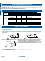
Section 9 - Seacoast Application
Ţ TKHRXWGRRUXQLWVKRXOGEHLQVWDOOHGDWOHDVWſPLOHawa\IURPWKHVDOWwDWHULQFOXGLQJVHDFRDVWVDQGLQODQGwDWHUwa\s,I
WKHXQLWLQVWDOOHGIURPſPLOHWRPLOHVawa\IURPWKHVDOWwDWHULQFOXGLQJVHDFRDVWVDQGLQODQGwDWHUwa\sSOHDVHfolloZWKH
LQVWDOODWLRQLQVWUXFWLRQEHOow
2DU
2DU
6Ha EUHHzH
Sea
2DU
6Ha EUHHzH
Sea
2DU
6Ha EUHHzH
Sea
3UoWH F Wion walls
2DU
Ţ ,QVWDOOWKHRXWGRRUXQLWLQDSODFHVXFKDVQHDUEXLOGLQJVHWFZKHUHLWFDQEHSUoWHFWHGIURPVHDEUHH]HZKLFKFDQGDPDJH
WKHRXWGRRUXQLW
Ţ ,I\RXFDQQoWavRLGLQVWDOOLQJWKHRXWGRRUXQLWE\WKHVHDVKRUHFRQVWUXFWDSUoWHFWLRQwDOODURXQGLWWREORFNWKHVHDEUHH]H
Ţ $SUoWHFWLRQwDOOVKRXOGEHFRQVWUXFWHGZLWKDVROLGPDWHULDOVXFKDV
FRQFUHWHWREORFNWKHVHDEUHH]HDQGWKHKHLJKWDQGWKHZLGWKRIWKHwDOO
VKRXOGEHWLPHVODUJHUWKDQWKHVL]HRIWKHRXWGRRUXQLW$lsoVHFXUH
oYHULQPPEHWZHHQWKHSUoWHFWLRQwDOODQGWKHRXWGRRUXQLWfRU
H[KDXVWHGDLUWRYHQWLODWH
Ţ ,QVWDOOWKHRXWGRRUXQLWLQDSODFHZKHUHwDWHUFDQGUDLQVPRoWKO\
Ţ ,I\RX
WoFOHDQWKHVHDwDWHUDQGWKH
GXVWRQWKHRXWGRRUXQLWKHDWH[FKDQJHU
System
09K
12K 15K 18K 24K
Outdoor
1U09BU1ERH 1U12BU1ERH 1U15RU1ERE
1U18RU1ERE 1U24SU1ERE
Indoor
AS09TB1HRH
AS12TB1HRH AS15TD1HRE AS18TD1HRE AS24TE1HRE
Cooling °F(°C)
14~115(-10~46)
14~115(-10~46) 0~115(-18~46) 0~115(-18~46) 0~115(-18~46)
Heati
ng °F(°C)
-4~75( -20~24)
-4~75(-20~24) -4~75(-20~24) -4~ 75(-20~24) -4~75(-20~24)
Power Supply
Volta
g
e, C
y
cle, Phase V/Hz/-
115/60/1
115/60/1 208-230/60/1 208-230/60/1 208-230/60/1
Compressor Type
Maximum Fuse Size A
20
20 20
20 25
Minimum Circuit Am
p
A
18
18 17 17 19
Connections Flare Flare Flare Flare Flare
Li
q
uid O.D. in
1/4
1/4 1/4 1/4 1/4
Suction O.D. in
3/8 3/8 1/2 1/2 1/2
Factory Charge Oz
26.5 35.3 40.6 40.6 67
Maximum Line Le
n
g
th Ft / m
66/20 66/ 83/2520 83/ 83/2525
Maximum Height Ft / m
33/10
33/ 50/1510
50/ 50/1515
DC Inverter Driven R otary
Model Name
Refrigerate Line
Operating Range
Electrical Data

[
This page intentionall
y
left blank.]

Model #: 1U09BU1ERH 1U12BU1ERH
1U15RU1ERE, 1U18RU1ERE 1U24SU1ERE
Issued Date: Nov,2016
-
 1
1
-
 2
2
-
 3
3
-
 4
4
-
 5
5
-
 6
6
-
 7
7
-
 8
8
-
 9
9
-
 10
10


Haier AS18TD1HRE Installation guide
- Type
- Installation guide
- This manual is also suitable for
Ask a question and I''ll find the answer in the document
Finding information in a document is now easier with AI
Related papers
-
Haier 1U18TE2VHA-1 Owner's manual
-
Haier AW12EH2VHA Installation guide
-
-
Haier AW12LC2VHA Installation guide
-
-
Haier AD07SL2VHB Installation guide
-
-
-
Haier HSU09VHGDBW Installation guide
-
Other documents
-
Lennox MCB and MWCB Single Zone Mini Split System User manual
-
Carrier 38GXC User manual
-
 Mitsubishi Electronics MSZ-FD09/12NA User manual
-
Mitsubishi Electric Mr. Slim MSZ-FD09NA User manual
-
-
GE AW15ES2VHB Installation guide
-
 Mitsubishi Electronics USA MSY-D30/36NA User manual
-
Johnson Controls Duct R-410A Installation guide
-
Electrolux ERS18E37HWI Installation guide
-
Johnson Controls (H,Y)VAHP072B31S Installation and Maintenance Manual

