Episode ES-GRLXRND-IM4-IC-B Installation guide

Type
Installation guide
INSTALLATION MANUAL
Impression Series
ES-IM4IC
ES-IM6-BP-SUB
page | 2
www.snapav.com Support 866.838.5052
WELCOME TO EPISODE
Thank you for purchasing a great product from Episode®, one of the best-sounding speaker lines available today.
We appreciate your purchase and are committed to providing the highest quality products possible.
Our Impression speakers and bandpass subwoofers allow dealers to work side-by-side with interior designers to
provide excellent sound for their customers while working within the aesthetic demands of the customer. Using
a minimalistic design, Impression in-ceiling speakers use a very small grille to avoid hindering the design of the
space. The Impression series uses 4-inch satellite speakers and a 6 1/2-inch bandpass subwoofer to deliver state-
of-the-art sound using three scientific principles: low distortion, wide dispersion, and flat-frequency response,
giving users complete and immersive audio that’s clean and accurate.
This kit provides fantastic flexibility for building different configurations, depending on the needs of the
customer—all while using a standard two-channel amplifier or AV receiver:
Subwoofer only
2 satellites only
2 satellites + 1 subwoofer
4 satellites only
4 satellites + 1 subwoofer
4 satellites + 2 subwoofers
All of the above can be wired to two channels of a standard amplifier or AV receiver while maintaining a safe
nominal impedance for today’s two-channel amplifiers. Minimum nominal system impedance from any of the
above configirations is 4 ohms.
Each ES-IM6-BP-SUB Impression Bandpass Sub comes with:
(1) Bandpass sub unit
(1) Port tube
(1) 4” port tube ceiling mount
(1) Serial wire connector
Mounting hardware
(1) Round grille
(1) Square grille
(1) Ceiling cutout template
Each ES-IM4IC Impression Satellite Speaker comes with:
(1) Impression Satellite Speaker
(1) Round grille
(1) Square grille
(1) Ceiling cutout template
TOOLS REQUIRED
#2 Phillips screwdriver
Flathead screwdriver
Sheetrock saw (hole must be slightly larger than a 4” hole saw)
Wire strippers
Note: This speaker system is designed only for installations where you have full, unobstructed access to ceiling
joists, such as in new construction or within unfinished attic space.
SPEAKER WIRING
Recommended Wiring
8 ohm (low-impedance) applications: 12 to 18 AWG, stranded, 2-conductor cable.
Best practices
In most cases, it is easiest to install a speaker system by pre-wiring and then installing the speakers.
Plan the locations of the speaker holes, volume control boxes, and the amplifier, and be sure wiring can be
routed everywhere necessary before cutting any holes.
Install spare wires for redundancy when you must run wire through a location that will not be accessible later.
When you aren’t enclosing speaker wire fully in conduit, make sure to leave enough of a wire loop for the
speaker wiring to allow you to connect the wires to the speaker either on the ground or at the top of the ladder.
Wiring connections
1. Strip the insulation on each conductor back ¼" and secure each wire into the appropriate terminal.
NOTE: Make sure no loose strands meet between the + and – connection and that the polarity is correct.
www.snapav.com Support 866.838.5052
page | 3
Wiring guides
ZONE 1
L R
ZONE 2
L R
ZONE 3
L R
ZONE 4
L R
0.1 - Discrete subwoofer driven from 1 zone / 2 channels
No satellite speakers
Single subwoofer
Conventional parallel wiring
(Impedance: 4.5Ω nominal / 4Ω minimum)
SPL output matches satellite sensitivity
ZONE 1
L R
ZONE 2
L R
ZONE 3
L R
ZONE 4
L R
0.1 (option) - Discrete subwoofer driven from 1 zone / 1 channel
No satellite speakers
Single subwoofer
Serial wiring
(Impedance: 9Ω nominal / 8Ω minimum)
SPL output 2 dB lower than satellite sensitivity
Use included
serial wire
connector
ZONE 1
L R
ZONE 2
L R
ZONE 3
L R
ZONE 4
L R
2.0 - Satellite full-range, driven from 1 zone / 2 channels
Two satellite speakers, high-pass filter OFF
No subwoofer
(Impedence: 8Ω nominal, 6Ω minimum)
ZONE 1
L R
ZONE 2
L R
ZONE 3
L R
ZONE 4
L R
2.1 - System, driven from 1 zone / 2 channels
Two satellite speakers, high-pass filter ON
Single subwoofer
(System impedance: 6Ω nominal / 4Ω minimum - Similar SPL between satellites and subwoofer)
page | 4
www.snapav.com Support 866.838.5052
ZONE 1
L R
ZONE 2
L R
ZONE 3
L R
ZONE 4
L R
4.0 - Multi-satellite, driven from 1 zone / 2 channels
Four satellite speakers, high-pass filter OFF
No subwoofer
Conventional parallel wiring
(Impedance: 4Ω nominal / 3Ω minimum)
ZONE 1
L R
ZONE 2
L R
ZONE 3
L R
ZONE 4
L R
4.1 - System, driven from 1 zone / 2 channels
Four satellite speakers, high-pass filter ON
Single subwoofer
Conventional parallel wiring
(System impedance: 6Ω nominal / 4Ω minimum)
ZONE 1
L R
ZONE 2
L R
ZONE 3
L R
ZONE 4
L R
4.2 - System, driven from 1 zone / 2 channels
Four satellite speakers, high-pass filter ON
Two subwoofers
Hybrid parallel/serial wiring
(System impedance: 6Ω nominal / 4Ω minimum)
Use included
serial wire
connector
www.snapav.com Support 866.838.5052
page | 5
NEW CONSTRUCTION BRACKET INSTALLATION
Whether positioning your Impression satellite speakers or the subwoofer ceiling port, the New Construction
Bracket (ES-IM4-BRKT-IC, not included) can simplify the process. These brackets make finish installation easier by
reserving the exact space and size needed for the speaker during the framing stage of home construction. During
the drywall process, the cutout can be precisely made around the bracket flange.
Important: For help determining the bracket location, see the respective speaker installation instructions below.
To install the new construction bracket:
1. Locate the area where the speaker will be placed in the ceiling. Keep in mind that the area should be free
from electrical wires, HVAC, and plumbing.
2. Connect the wings (or edge plate,
if needed) to the bracket.
3. Position the bracket between two
joists and secure each bracket
wing or edge plate with
two screws, nails, or staples.
ZONE 1
L R
ZONE 2
L R
ZONE 3
L R
ZONE 4
L R
4.2 (option) - System, driven from 2 zones / 4 channels
Four satellite speakers, high-pass filter ON
Two subwoofers
Hybrid parallel/serial wiring
(Satelite impedance: 6Ω nominal / 4Ω minimum)
(Subwoofer impedence: 9Ω nominal / 8Ω minimum)
Use included
serial wire
connector
JoistJoist
JoistJoist
page | 6
www.snapav.com Support 866.838.5052
SATELLITE SPEAKER INSTALLATION
General guidelines
Mount into an exact 4.1-inch hole.
If you plan to install the optional back-can for the satellite speakers, you must attach the back-can to the new
construction bracket and run wire to them before the drywall is installed.
CAUTION: There is no way to retrofit the optional back-can for the satellite speakers after the drywall is
installed. To use the optional back-can, the New Construction Bracket must be used, and both the New
Construction Bracket and back-can must be installed in the ceiling before drywall installation, unless you
have full access to an open area above the speaker, for example, in an openly accessible attic.
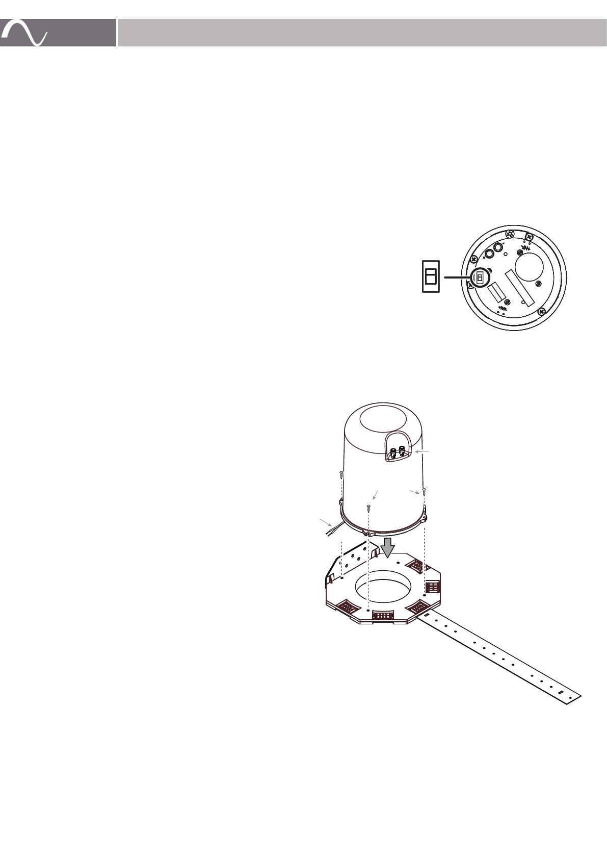
Setting the high-pass filter switch
The high-pass filter switch is located on the back of the speaker. The high-pass selection, ON or OFF, should be
determined before installing the speaker.
In the ON (default) position, the high-pass filter limits the low bass
frequencies that are reproduced by the ES-IM4IC speaker. The high-
pass filter allows for a smooth transition from the ES-IM4IC speaker to
the ES-IM6-BP-SUB subwoofer.
If the ES-IM4IC will be used without a subwoofer, the high-pass filter
switch should be set to OFF.
Mounting the speakers
1. Choose a location for each speaker that is free of obstructions created
by joists, HVAC ductwork, electrical wire runs, plumbing, or anything
else that might not allow for the depth of the speaker or create interference or noise.
2. To make installation easier, install a New Construction Bracket (ES-IM4-BRKT-IC, not included) at the location
where you want the finished speaker grille. See “New Construction Bracket Installation” above.
Caution: The New Construction Bracket is required if you want to use the optional back-can.
3.
Optional back-can:
After you have determined the
speaker locations and have installed the
New Construction Brackets, install a
back-can onto each bracket.
4. Run speaker wire to the locations where the
satellite speakers will be installed. If you’ve
installed back-cans, connect the wiring to the
back-can’s wire terminals at this time.
Tip: If you do not use a back-can, you will need
to fish the wiring through the opening after
the ceiling is installed, so it’s a good idea to
temporarily secure the end of the wiring against
a nearby joist or the New Construction Bracket
so it’s within easy reach of the opening and out
of the way of potential ceiling finishing tools.
Tip: Before the ceiling is installed, confirm and
test speaker wiring.
5. After the ceiling is installed, cut out the opening
using the New Construction Bracket or the
ceiling cutout template as a guide.
6. If you did not use a back-can, fish the wiring out
of the ceiling through the opening.
7. Secure the wiring (or the back-can’s wire pigtail)
to the speaker’s wire terminals.
ON
OFF
HIGH-PASS
Wire terminals
Screw (x4)
Wire
pigtail
www.snapav.com Support 866.838.5052
page | 7
8. Insert the speaker into the opening, then tighten the Phillips screws located on the front baffle to rotate and
tighten the mounting doglegs to the ceiling. The mounting doglegs will move outward and tighten to secure
the speaker to the drywall.
Caution: If using a power
screwdriver or drill, always
use the lowest torque setting.
Never over-tighten.
9. Attach the metal grille (Round or Square) to the speaker face by placing the grille over the edge of the frame.
The grille self-centers onto the magnet attachment system incorporated in the frame.
SUBWOOFER INSTALLATION
Note: This subwoofer is designed only for installations where you have full, unobstructed access to ceiling joists,
such as in new construction or within unfinished attic space.
1. Choose a location for the subwoofer and port tube that is free of obstructions created by joists, HVAC
ductwork, electrical wire runs, plumbing, or anything else that might not allow for the depth of the speaker or
create interference or noise.
Tip: It’s best to first determine the location of the ceiling opening, and work backward from there to determine
locations for the sub unit and port tube.
2. Make sure the sub unit’s port tube will be able to reach the planned ceiling opening, and that both ends of the
tube can be securely connected at both ends (about 0.5 meter, or 18 inches, from sub unit to opening).
3. To make installation easier, install a New Construction Bracket (ES-IM4-BRKT-IC, not included) at the location
where you want the ceiling port.
4. Use large lag screws or lag bolts to secure the sub unit to the side of the ceiling joist. To best isolate the sub
enclosure, install the two foam pads onto the bottom of the sub enclosure between the enclosure and the
joist, and maintain an air space between the side of the enclosure and the bottom edge of the joist.
5. Connect speaker wiring and jumper, if required, to the sub unit.
6. Securely attach the port tube to the sub unit by using the provided clamp. Important: Because the sub unit
will be inaccessible after the ceiling is installed,
make absolutely sure
the port tube is securely attached to the
sub.
Hangers
at top
Foam pad
Foam pad
Air space
520 mm (20 1/2”)
About 0.5 meter (18”)
Tighten
securely
4” port tube
ceiling mount
Tighten
securely
Wiring
connections
JoistJoist
JoistJoist
Hangers
at top
Air space
END VIEW
SIDE VIEW
220 mm (8 5/8”)
215 mm (8 1/2”)
CeilingCeiling
Ceiling
Ceiling
page | 8
www.snapav.com Support 866.838.5052
Tip: Because you will need to fish the tube through the ceiling opening after the ceiling is installed, it’s a good
idea to temporarily secure the end of the tube against the joist so it’s within easy reach of the opening and
out of the way of potential ceiling finishing tools.
Tip: Keep the port tube as straight as possible, avoiding any unnecessary bends. If there is slack in the port
tube, you can remove material to shorten it.
Tip: Before the ceiling is installed, confirm and test speaker wiring.
7. After the ceiling is installed, cut out the port opening using the New Construction Bracket or the ceiling cutout
template as a guide.
8. Fish the sub port tube out of the ceiling through the port opening, then secure it to the port tube ceiling mount
by using the provided clamp.
9. Insert the port tube ceiling mount into the ceiling opening, then tighten the Phillips screws located on the front
baffle to rotate and tighten the mounting doglegs to the ceiling. The mounting doglegs will move outward and
tighten to secure the speaker to the drywall.
Caution: If using a power screwdriver or drill, always use the lowest torque setting. Never over-tighten.
10. Attach the metal grille (Round or Square) to the speaker face by placing the grille over the edge of the frame.
The grille self-centers onto the magnet attachment system incorporated in the frame.
GRILLE PAINTING TIPS
Paint grilles only when removed from the speakers, and make sure the holes do not get clogged with paint.
www.snapav.com Support 866.838.5052
page | 9
SPECIFICATIONS
ES-IM4IC Satellite Speaker
Tweeter
19 mm (3/4”) neo magnet
Woofer
89 mm (3 1/2”) carbon/aramid fiber cone with a corrugated rubber surround
Impedance
8 ohms nominal; 6 ohms minimum
Power handling
100W maximum
Frequency response
70 Hz to 20 kHz: ±3 dB
Sensitivity
85 dB SPL (2.8V/1 meter)
Shipping weight
3.1 lb (1.4 kg) each
High-Pass crossover frequency
125 Hz @12 dB per octave (High-Pass ON)
Grille
Shipped with round and square 124 mm (4 29/32”) micro-perforated steel
grilles
Cutout diameter
102 mm (4 1/64”)
Dimensions (Diameter / Depth)
114 mm x 92 mm (4 1/2” x 3 5/8”)
ES-IM6-BP-SUB Subwoofer
Woofer
165 mm (6 1/2”) dual voice coil, fabric-coated, paper cone with a rubber
surround
Power handling
100W maximum
Frequency response
40 Hz - 125 Hz - ±3 dB
Impedence
6 ohms nominal; 4 ohms minimum
Sensitivity
87 dB SPL (2.8V/1 meter)
Internal crossover frequency
125 Hz @12 dB per octave
Shipping weight
29 lb (13.54 kg) each
Grille
Shipped with round and square 124 mm (4 29/32”) micro-perforated steel
grilles
Enclosure Dimensions (W x H x D)
215 mm x 220 mm x 520 mm (8 1/2” x 8 5/8” x 20 1/2”)
Port tube dimensions
(Diameter / Length)
86 mm x 559 mm (3.39” x 22”)
Ceiling port cutout diameter
102 mm (4 1/64”)
page | 10
www.snapav.com Support 866.838.5052
TROUBLESHOOTING
Episode® speakers are designed to function trouble-free. Most problems that occur are due to simple issues.
If you have trouble, check the list of simple fixes below. If the problem persists, contact Customer Service at
1.866.838.5052.
No sound
Verify that there is audio coming from the source selected. Select another source, if necessary.
Ensure that the audio source is turned on and connected properly.
WARRANTY
Limited Lifetime Warranty
Episode speakers have a Lifetime Limited Warranty. This warranty includes parts and labor repairs on all
components found to be defective in material or workmanship under normal conditions of use. This warranty
shall not apply to products which have been abused, modified or disassembled. Products to be repaired under
this warranty must be returned to SnapAV or a designated service center with prior notification and an assigned
return authorization number (RA).
CONTACTING TECHNICAL SUPPORT
(866) 838-5052
techsupport@snapav.com
snapav.com
www.snapav.com Support 866.838.5052
page | 11
© 2020 Wirepath Home Systems, LLC
200-00689-A 20-08-05-0850 TW
Copyright ©2020, Wirepath Home Systems, LLC. All rights reserved. Control4 and Snap AV and their respective logos are
registered trademarks or trademarks of Wirepath Home Systems, LLC, dba “Control4” and/or dba “SnapAV” in the United
States and/or other countries. Episode and Wirepath are also registered trademarks or trademarks of Wirepath Home
Systems, LLC. Other names and brands may be claimed as the property of their respective owners. All specifications
subject to change without notice.
  • Page 1 1
  • Page 2 2
  • Page 3 3
  • Page 4 4
  • Page 5 5
  • Page 6 6
  • Page 7 7
  • Page 8 8
  • Page 9 9
  • Page 10 10
  • Page 11 11
  • Page 12 12

Episode ES-GRLXRND-IM4-IC-B Installation guide

Type
Installation guide

Ask a question and I''ll find the answer in the document

Finding information in a document is now easier with AI