Frigidaire FRS22PYC20 Owner's manual
- Category
- Split-system air conditioners
- Type
- Owner's manual
This manual is also suitable for

www.frigidaire.com USA 1-800-944-9044 www fr gidai_re.ea Canada 1-800-265-8352

Welcome to the world of
simple handling and no worries
Thank you for choosing Frigidaire. This manual contains all of the information
required to guarantee your safety and the appropriate use of your air
conditioner.
Please read all of the instructions before using the air conditioner and keep
this manual for future reference.
We know you will enjoy your new air conditioner and thank you for choosing
our product.
We hope you will consider us for future purchase.
Environmental advices i_-_ _
The packaging material used is recyclabte. We
recommend that you separate plastic, paper and
cardboard and give them to recycling companies.
If you need to dispose of this appliance in the future,
do NOT throw it away with the rest of your domestic
garbage.
Attention
Theair conditioner that you have bought may be slightly differentfrom the one
illustrated in this manual. Pleasereferto the information relatedto the model
you have.
Thisair conditioner isfor domestic useonly. It isnot reccomendedfor
commercial or industrial use.

Contents
01. Welcome ........................................................................................... 01
02. Environmental advices .......................................................................... 01
03. Contents ............................................................................................... 02
04. Safety precautions ....................................................................... 04
05. Installation:
5.1 Choosing the installation site ....................................................... 06
5.2 Parts list ..................................................................................... 08
5.3 Indoor unit installation ...................................................... 10
5.4 Outdoor unit installation ............................................................ 14
5.5 Refrigerant piping connection ..................................................... ] 6
5.6 Electrical work ...................................................................... 18
5.7 Air Purge ................................................................................... 21
5.8 Electrical safety ..................................................................... 24
5.9 Gas leakcheck ........................................................................... 24
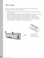
5.10 Test running .............................................................................. 25
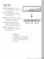
06. Operation:
6.1 Preparing the device for operation ............................................ 26
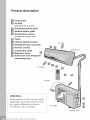
6.2 Product description ............................................................. 27
6.3 Remote control ......................................................................... 29
- Remote control operation
- Remote control specifications
- Remote control battery
- When should the batteries be replaced
- To replace batteries
- Remote control instructions
6.4 Remote control description ......................................................... 31
- On/Off
- Mode
4-
- Fan
-
- TIMER ON
- TIMER OFF
-Clock
- Blow
- TEMP
- Turbo
- Sleep
- LIGHT
6.5 INTRODUCTION FOR SPECIALFUNCTION ................................. 37

6.6 Howtheair conditionerworks........................................33
-Automaticoperation
-Cool/heatandfanonlyoperation
- Dryoperation
-Airflowdirectionadjustment
-Sleepmode
-Timeroperation
-Optimal operation
6.7 How to use the indoor unit...................................................... 37
- Adjusting air flow direction
- Adjusting the vertical air flow direction (up/down)
- Toset the horizontal air flow direction (left/right)
- Toautomatically swing the air flow direction (up/down)
6.8 Manual operation ..................................................................... 39
07. Maintenance .................................................................................... 40
08. Operation tips ...................................................................................... 42
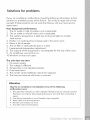
09. Solution for probtems ........................................................................... 44
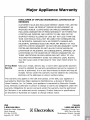
10.Major appliance warranty ...................................................................... 45

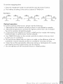
Safety precautions
To prevent injury to the user or other people and property damage, the
following instructions must be followed.
incorrect operation due to ignoring of instructions may cause harm or
damage. The seriousness is classified by the following indications.
Connect with the power properly.
Otherwise, it may cause eledric
shock or fire due to excess heat
generation.
Always ensure effective grounding.
No grounding may cause electric
shock.
Disconnect the power if strange
sounds, smell, or smoke comes
from it. It may cause fire and
electric shock.
4. Do not operate or stop the unit by
switching on or off the power. It
may cause electric shock or fire due
to heat generation.
5. Do not operate with wet hands or in
damp environment. It may cause
electric shock.
6. Do not allow water to run into
electric parts. It may cause failure of
machine, electric shock or fire.
7. Do not use the power cord near
flammable gas or combustibles,
such as gasoline, benzene, thinner,
etc. It may cause an explosion or fire.
8. Do not use the power cord close to
heating appliances. It may cause
fire and electric shock.
9.Do not damage or use an
unspecified power cord. It may
cause electric shock or fire.
21 .Do not place heavy object on the
power cord and ensure that the
cord will not be compressed. There
is danger of fire or electric shock.

11.Do not open the unit during
operation. It may cause electric
shock or injury.
12.Do not drink water drained
from air conditioner. It contains
contaminants and could make
you sick.
13.Do not disassemble or modify unit.
It may cause failure of appliance
and electric shock.
14.When the air filter isto be
removed, do not touch the metal
parts of the unit. It may cause an
injury.
15.When the unit is to be cleaned,
switch off, and turn off the circuit
breaker. Do not clean unit when
power is on as it may cause fire,
electric shock or injury.
16.Avoid direct exposure of occupants
to air flow.
17.Turn off the main power switch when
not using the unit for a long time.
18.The air conditioner may be dusted
with an oil free doth, or washed
with a cloth dampened in a solution
of warm water and mild dishwashing
detergent. Rinsethoroughly and wipe
dry. Wring excess water from cloth
before wiping around controls.
19.Ensure that the installation bracket of
the outdoor unit will not damage
due to prolonged exposure. If
bracket damages, there will be
concern of damage due to falling
of unit.
20.Always insert the filters securely.
Clean filter once every two weeks.
Operation without filters may
cause failure.
2 ] .Always install circuit breaker and a
dedicated power circuit. No
installation may cause fire and
electric shock.
22.Do not place obstacles around air-
inlets or inside of air-outlet. It may
cause failure of appliance or
accident.

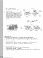
Installation
installation warnings:
1. Carefully read the installation manual before beginning.
2. Follow each step as shown.
3. Observe all local, state, and national electrical codes and by qualified,
licensed, authorized personnel only.
4. Payattention to danger and safety notices
Choosing the installation site
Precautions for Installation
Installation at the following sites may cause problems. If you must inevitably install
the unit at one of these sites, please consult your ]oca] distributor beforehand:
1. Sites with machine oil.
2. Sites with a high concentration of salinity, such as coastal areas.
3. Sites with sulfuric gas, such as hot water springs.
4. Sites with high frequency equipment, such as wireless equipment, welding
machines and medical installations.
5. Sites with flammable gases or volatile material.
6. Sites with special environmental conditions.
7. Laundry rooms.
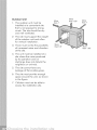
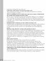
indoor Unit
1. The unit must be installed at a site
that does not obstruct the flow of
air.
2. The site must support the weight of
the indoor unit.
3. The site must be easily accessible
for maintenance and replacement
of the air filter.
4. The site must allow for the
necessary space around the indoor
unit, as shown in the sideward
figure.
5. There should be at least 3 feet (1
meter) between the unit and radio
or television devices. It is ideal
that the unit be installed at the
center.
6. It must be far from fire, smoke or
flammable gases.
7. The indoor unit must be at least 8.2
ft(2.5 meters) from the ground.
8. The site must allow for the easy
removal of the connector pipe and
drain hose.
9. The unit must be installed at a site
protected from direct sunlight.
More
More
than 6"
More
than 8.2'
than 6"

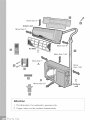
Outdoor Unit
. The outdoor unit must be
installed at a convenient site
that is not exposed to strong
winds. The site should be dry
and well ventilated.
2. The site must support the weight
of the outdoor unit and allow
for vertical installation.
3. There must not be the possibility
of increased noise and vibration
at the site.
4. The unit must be installed at a
site where the noise produced
by its operation and air
discharge does not disturb the
neighbors or animals.
5. The site cannot have any
leakage of flammable gases.
6. The site must provide enough
space around the unit, as shown
in the figure.
7. Children must not be able to
access the installation site.
More
than 1'
More
than 6.6'
More
than 1.65'
More
than 1'
More
than 1.65'
i

Partslist
NUMBER PART NAME
1
2
6
7
8
installation plate
Drain Joint
Self-tapping scr
ewA#7 XI"
Remote controller
capacity <-.18000 Btu's
capacity > 24000 Btu's
Connecting
pipe
assembly
Drainage
Plug
Liquid side
Gas side
@1/4"
@3/8" (capacity <..12000 Btu's)
@1/2" (capacity <-.18000 Btu's)
@5/8" (capacity >/24000 Btu's)
capacity = 18000 Btu's
capacity = 21500 Btu's
Remote Controller holder
Self-tapping screw B #4 X 3/8"
QTY.
1
1
5
10
1
3
2
1
2
Indoor unit
f
4
Outdoor unit
} :,:,::

More than 6"
Indoor unit
More than 6"
Air filter
More than 6"
More than 1.65'
More than 1'
A
More
than 1.65'
B C
More than 6.6' Outdoor
unit
Attention
]. This illustration is for explanation purposes only.
2. Copper tubes must be insulated independently

Indoor unit installation
Installation plates and dimensions
Indoor unit outline,, ................
6" or more from
I the ceiling Installation plate
/
/
/
<--]2000 Bfu's (A:33.3]" B:10.83")
6" or more from
I the Installation plate
ceiling
Indoor unit outline A /
/
eq"
.................................................... .7/. ......................................... _
6" or mor
from the wall I
!
Refrigerant pipe I i
hole (right) O 2.56" ! ......_..,
6" or more
from the wall
Refrigerant pipe
hole (right) O 2.56"
=18000 Bfu's (A:36.c27'' B:] 1.73")

6" or more from
the ceiling I Installation plate
AI
I
Indoor unit outline I /
-""Tp" ....................................... _ ........................... _ { " or more
l, f - - _u _ _ from the wall
o (:3 o • • o / ° _ (:3oo • e
_i"ormore|, l'.ll':0 o_.=."=--" "';=:.._ 0 .11.'/ ,
from the wall|! I_ ;------',, -- ,,"--'4 ;='/ !_'_
_e e
Refrigerant pipe I= ! H', I]'llU21 I_llU21fqt_ ! I Refrigerant pipe
hole (right) O 2.56" !i _--_'1 _ | | hole (right) O 2.56"
=21500 Bfus (A:39.69" B:12.40")
Fixing the Installation Plate
1. Install the installation plate
horizontally over the structural Attention
parts on the wall using the spaces
indicated on the plate, as shown Fitthe Installation Plateand drill holes
in the figures above, in the wall according to thewall
2. In the case of tiled, concrete or structureand corresponding mounting
similar walls, create 0.2" pointsonthe installation plate
diameter holes. Place anchorage (Dimensionsare in "mm" unless
supports for the appropriate otherwisestated).
assembly screws.
3. Fix the installation plate to the Installation plate
walt with eight A type screws. O @ @
4. At all times securing to the wall
studs is recommended.
Drilling the Hole
Wall
1. Determine the position of the IIndoor unit [ Outdoor unit]
hole for the pipes using the
installation plate and drill the
pipe hole so that it is tilted slightly
downward.
2. Always use a pipe cover with an
opening when drilling.

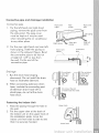
Connective pipe and drainage installation
Connective pipe
1. For the left-hand and right-hand
piping, remove the pipe cover from
the side panel. The pipe cover
must be kept as it may be used
when relocating the air conditioner
to any other place.
.
For the rear-right-hand and rear-left-
hand piping, install the piping as
shown in the sideward figure. Bend
the connective pipe to be laid at
a height of 1.69" or tessfrom
the watt. Fixthe end of the
connective pipe.
Pipe cover Pipe Pipe cover
(right) holder (left)
piping
Right piping _ nRier.anrnright Riea_ft
piping p p y
Indoor unit Connective
outline pipe
yy ? yyy yyy yyy yy --
ssssssssssii;_
Drainage
1. Runthe drain hose sloping
downward. Do not install the drain
hose as illustrated sideward.
.
When connecting extension drain
hose, insulate the connecting part
of extension drain hose with a
shield pipe, do not let the drain
hose slack.
Fastening the Indoor Unit
1, Pass the piping through the hole in
the wall,
2. Put the upper claw at the back of
the indoor unit on the upper hook of
the installation plate, move the
indoor unit from side to side to see
that it is securely hooked.
Do not block
water flow
by a rise.
Do not block
water.flow
Do not put the end
of drain hose into water.
Upper hook \
Lower hook

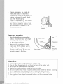
3. Piping can easily be made by
lifting the indoor unit with a
cushioning material between the
indoor unit and the wall. Get it
out after finish piping.
4. Push the lower part of the indoor
unit up on the wall, Then move
the indoor unit from side to side,
up and down to check if it is
hooked securely.
Cushioning
material
Piping and wrapping
1. Bundle the tubing, connecting
cable, and drain hose with tape
securely and evenly as shown
in the sideward figure.
2. Because the condensed water
from rear of the indoor unit is
gathered in ponding box and is
piped out of room, do not put
anything else in the box.
lndoor unit
Cablnection
Ponding
box
X
._ Pipe room
Connective
Jpipe
Wrapping
belt
Attention
1. Connect the indoor unit first, then the outdoor unit.
2. Do not allow the piping to let out from the back of the indoor unit.
3. Be careful not to let the drain hose slack.
4. Both of the auxiliary piping should be heat insulation.
5. Be sure that the drain hose is located at the lowest side of the bundle. Locating
at the upper side may cause drain pan to overflow inside the unit.
6. Never intercross nor intertwist the power wire with any other wiring.
7. Run the drain hose sloped downward to drain out the condensed water
smoothly.

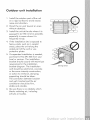
Outdoor unit installation
1. Install the outdoor part of the unit
on a rigid surface to avoid excess
noise and vibration.
2. Direct the air vent toward an area
without obstacles.
3. Install the unit at the site where it is
exposed to as little wind as possible,
especially in areas where it is
frequently windy.
4. If the installation site is exposed to
heavy winds, such as in coastal
areas, place the unit along the
widest part of the wall or use
protective plates.
5. If suspended installation is needed,
purchase kit No.EAt40S from your
local or servicer. The installation
bracket should accord with technique
requirement in the installation
bracket diagram. The installation
wall should be solid brick, concrete
or the same intensity construction,
or action to reinforce, damping
supporting should be taken.
The connection between bracket
and wall, bracket and the air
conditioner should be firm,
stable and reliable.
6. Be sure there is no obstacle which
blocks radiating air, including
schrubs or bushes.
Strong wind

Settlement of outdoor unit
Anchor the outdoor unit tightly and
horizontally on a concrete or rigid
mount with a bolt and nut 0.39" or
0.32" diameter (Purchased separately).
14 A _'1
r_ Air inl_ rzT_
l_/_ _ _ t
_Air outlet
Outdoor unit dimension ff(WxHxD) A(ff) B(fl)
2.78'xl .77'xl .05' 1.77' 0.94'
2.92'x2.30'x1.30' 1.84' 1.18'
3.02'x2.59'x1.40' 2.00' 1.28'
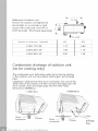
Condensate drainage of outdoor unit
(no for cooling only)
The condensate and defrosting water formd during heating
in the outdoor unit can be properly discharged by drainage
p_pe.
Installation method:Insert the drain connection into one of the
025 holes of the chassis and then connect drainage pipe with
drain nozzle. Insert drainage plugs into the other holes
(Only for>12000Btu's).
_12000 Btu's >18000 Btu's
connection
connection
Drainage
Plug

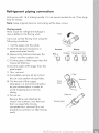
Refrigerant piping connection
Unit comes with ] 6.4' tubing bundle. It is not recommended to cut. Iftoo long,
loop for excess.
Note: Keep original bend so not kinking of the tube occurs.
Flaring work
Main cause for refrigerant leakage is
due to defect in the flaring work.
Carry out correct flaring work using the
following procedure:
1. Cut the pipes and the cable.
A) Use the piping kit accessory or
pipes purchased locally.
B)Measure the distance between the
indoor and the outdoor unit.
C) Cut the pipes a little longer than the
measured distance.
D) Cut the cable 4.9ft longer than the
pipe length.
2. Burr removal
A) Completely remove all burrs from
the cut cross section of pipe/tube.
B) Putthe end of the copper
tube/pipe in a downward direction
as you remove burrs in order to
avoid dropping burrs into the
tubing.
3. Put nut on.
Remove flare nuts attached to
indoor and outdoor unit, then put
them on pipe/tube having
completed burr removal.fit is not
possible to put them on after flaring
work)
Pipe_
Correct Wrong
9(}_ Obliqu2 Roughness_ J'l.Burr
Point
down
,are:u:
Cooper !ube

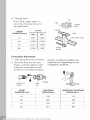
4. Flaring work.
Firmly hold copper pipe in a
die in the dimension shown in
the table below.
A (inch)
OUTER
DIAMETER (inch) Max. Min.
1/4 0.051 0.028
3/8 0.063 0.039
1/2 0.071 0.039
5/8 0.087
Handle
Clamp
handle
Copper
pipe
Yoke
ow mark
Connection Adiustment
1. Align the pipes to be connected.
2. Screw the flare nut with your
fingers, and then tighten it with
a spanner and torque wrench,
as shown in the following figure.
Caution: Excessive twisting may
break the nut, depending on the
installation conditions.
Indoor unit Flare
tubing nut
Pipings
OUTER
DIAMETER (inch)
1/4
3/8
1/2
TIGHTENING
TORQUE (Ibf.in)
139
260
434
ADDITIONAL TIGHTENING
TORQUE (Ibf.in)
174
304
477
5/8 651 694

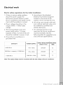
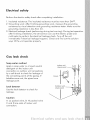
Electrical work
Electric safety regulations for the initial Installation
1. If there is serious safety problem
about the power supply, the
technicians should refuse to install
the air conditioner and explain to the
client until the problem is solved.
2. Power voltage should be in the
range of 90%- ] ]0%of rated
voltage.
3. The circuit protector and main
power switch with a ] .5 times
capacity of Max. Current of the unit
should be installed in power circuit.
4. Ensure the air conditioner is
grounded well.
5. According to the attached
Electrical Connection Diagram
located on the panel of the
outdoor unit to connect the wire.
6. All wiring must comply with local
and national electrical codes and
be installed by qualified and
skilled electricians.
7. An individual branch circuit
used only for this air conditioner
must be available. See the
following table for suggested wire
sizes and fuse specifications:
iNPUT RATED AMP AWG WiRE
CAPACITY POWER SUPPLY
Switch / Fuse SiZE
-!<9000 Btus 115VW 60Hz 25A/25A 12
9000 Btu's < capacity _<12000 Btu's 115VW 60Hz 25A/25A 12
!......................................................................................................................................................................................g w w..............................................................
> 12000 Btus 208/230VW 60Hz 25A/25A 12 _i
Note: The supply voltage must be consistent with the rate voltage of the air conditioner.

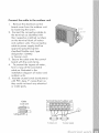
Connect the cable to the indoor unit
1. The inside and outside connecting
cane can be connected without
removing the front grille.
2. Connecting cane between indoor
unit and outdoor unit shall be
approved poJychJoroprene
sheathed flexible cord, type
designation 16AWG or heavier
cord,
3. Lift the indoor unit panel up,
remove the electrical box cover by
loosening the screw.
4. Ensurethe colour of wires of
outdoor unit and the terminal Nos.
are the same to the indoors
respectiveJy.
5. Wrap those cables not connected
with terminals with insulation
tapes, so that they will not touch
any eJectricaJcomponents. Secure
the cable onto the control board
with the cord damp.
Electrical box
cover
0.39"
Cable
Code wire
Terminal block of indoor unit
To Outdoor Unit
Page is loading ...
Page is loading ...
Page is loading ...
Page is loading ...
Page is loading ...
Page is loading ...
Page is loading ...
Page is loading ...
Page is loading ...
Page is loading ...
Page is loading ...
Page is loading ...
Page is loading ...
Page is loading ...
Page is loading ...
Page is loading ...
Page is loading ...
Page is loading ...
Page is loading ...
Page is loading ...
Page is loading ...
Page is loading ...
Page is loading ...
Page is loading ...
Page is loading ...
Page is loading ...
Page is loading ...
Page is loading ...
-
 1
1
-
 2
2
-
 3
3
-
 4
4
-
 5
5
-
 6
6
-
 7
7
-
 8
8
-
 9
9
-
 10
10
-
 11
11
-
 12
12
-
 13
13
-
 14
14
-
 15
15
-
 16
16
-
 17
17
-
 18
18
-
 19
19
-
 20
20
-
 21
21
-
 22
22
-
 23
23
-
 24
24
-
 25
25
-
 26
26
-
 27
27
-
 28
28
-
 29
29
-
 30
30
-
 31
31
-
 32
32
-
 33
33
-
 34
34
-
 35
35
-
 36
36
-
 37
37
-
 38
38
-
 39
39
-
 40
40
-
 41
41
-
 42
42
-
 43
43
-
 44
44
-
 45
45
-
 46
46
-
 47
47
-
 48
48


Frigidaire FRS22PYC20 Owner's manual
- Category
- Split-system air conditioners
- Type
- Owner's manual
- This manual is also suitable for
Ask a question and I''ll find the answer in the document
Finding information in a document is now easier with AI
Related papers
-
Frigidaire FFHP242ZQ2 User guide
-
Frigidaire FFHP362SQ2 Complete Owner's Guide
-
Frigidaire FFMS221SQ2 English
-
-
Frigidaire FFHP302SQ2 Owner's manual
-
Frigidaire FRS12PYC1 User manual
-
Frigidaire FRS093LC1 User manual
-
Frigidaire FFHP094WS1 Installation guide
-
Frigidaire FRS124YW10 Owner's manual
-
Other documents
-
GREE Cozy Owner's manual
-
Midea Air Conditioner Owner's manual
-
mabe MEE09VV Owner's manual
-
Friedrich MWM18Y3J Operating instructions
-
Becken AR CONDICIONADO INVERTER I 12BTU Owner's manual
-
MUND CLIMA MUP-12+062X2C User manual
-
LG APNQ55GT3M2 Installation guide
-
-
-