Page is loading ...

Non-Contact Infrared Thermometers
DT-8833
Operation Manual

- -
2
TABLE OF CONTENTS
INTRODUCTION………………………………………………3
FEATURES…………………………………………………… 3
WIDE RANGE APPLICATION ………………………………4
SAFETY………………………………………………………… 4
DISTANCE & SPOT SIZE…………………………………… 5
SPECIFICATIONS…………………………………………… 6
FRONT PANEL DESCRIPTION…………………………… 8
INDICATOR…………………………………………………… 9
BUTTONS………………………………………………………9
MEASURMENT OPERATION………………………………12
BATTERY REPLACEMENT………………………………..15
NOTES……………………………………………………….15
MAINTENANCE & CLEARING…………………………. 19

- -
3
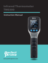
INTRODUCTION
Thank you for purchase of the 8833 IR Thermometer. This
device offers non-contact (infrared) temperature
measurements capability. The built-in laser pointer increases
target accuracy while the backlight LCD and handy
push-buttons combine for convenient, ergonomic operation.
Type K thermocouple functionality is also built-in. Proper use
and care of this meter will provide years of reliable service.
FEATURES:
Precise non-contact temperature measurement
Type K temperature Measurement
Unique flat surface, modern housing design
Built-in laser pointer
Automatic Data Hold
Automatic Power Off
℃/℉ switch
Emissivity Digitally adjustable from 0.10 to 1.0
MAX,MIN,DIF, AVG record
LCD with Backlight
Automatic range selection
Resolution 0.1ºC(0.1ºF)

- -
4
Trigger lock
High and Low alarm
Obtain Emissivity
WIDE RANGE APPLICATION:
Food preparation, Safety and Fire inspectors, Plastic
molding, Asphalt, Marine and Screen printing, measure ink
and Dryer temperature, HVAC/R, Diesel and Fleet
maintenance.
1. SAFETY
Use extreme caution when the laser beam is turned on.
Do not let the beam enter your eye, another person’s
eye or the eye of an animal.
Be careful no to let the beam on a reflective surface
strike your eye.
Do not allow the laser light beam impinge on any gas
which can explode.

- -
5
Distance & Spot Size
As the distance (D) from the object increases, the spot size
(S) of the area measured by the unit becomes larger. The
relationship between distance and spot size for each unit is
listed below. The focal point for each unit is 914mm (36”).
The spot sizes indicate 90% encircled energy.
Fig: 1
MODEL:8833 D:S=13:1
Sensor Beam
Dmm
Distance(D) to Spot Size(S) inch
16mm
Laser Beam
S
10@130 30@390 50@650
0.4@5.2 1.2@15.6 2.0@26

- -
6
2.
SPECIFICATIONS
TK measurement: TK Temperature
range
-50 to 1370 oC
(-58 to 2498℉)
Resolution -50 to 1370 oC 0.1 oC
-58 to 1999℉ 0.1℉
2000 to 2498℉ 1℉
Accuracy -50 to 1000 oC ± 1.5% of reading + 3℃(±℉)
1000 to 1370 oC ± 1.5% of reading + (±3.6℉)
IR Measurement:
IR Temperature range -50 to 800 oC (-58 to 1472℉)
D: S 13:1
Resolution 0.1 oC (0.1℉)
Accuracy -50 to -20℃(-58 to -4℉): ±5 oC (±9℉)
-20 to 200℃(-4 to 392℉): ± 1.5% of reading + 2℃(±3.6℉);
200 to 538℃ (392 to 1000℉): ± 2.0% of reading +2℃(±3.6℉);
538 to 800℃(1000 to 1472℉): ± 3.5% of reading ± 5℃(±9℉)

- -
7
Response time less than 1 second
Spectral response 8~14um
Emissivity Digitally adjustable from 0.10 to 1.0
Over range indication LCD will show “-0L”,”0L”
Polarity Automatic (no indication for positive
polarity);Minus (-) sign for negative polarity
Diode laser output <1mW, Wavelength 630~670nm,
Class 2(II) laser product
Operating temp. 0 to 50℃(32 to 122℉)
Storage temp. –20 to 60℃ (-4 to 140℉)
Relative humidity 10%~90%RH operating, <80%RH
storage
Power supply 9V battery, NEDA 1604A or IEC 6LR61,
or equivalent
Weight 290g (10.2 oz.)
Size 100 x 56 x 230mm (3.9 x 2.2 x 9.0”)
Safety “ CE ” Comply with EMC

- -
8
Note:
Accuracy: Given at 18 to 28 oC (64
to 82
℉), less
than 80 % RH.
Field of View: Make sure that the target is larger than
the unit’s spot size. The smaller the target, the closer
you should be to it. When accuracy is critical, make
sure the target is at least twice as large as the spot
size.
3. FRONT PANEL DESCRIPTION
① IR sensor
② Laser pointer beam
③ LCD Display
④ down button
⑤ up button
⑥ mode button
⑦ laser/backlight button
⑧ Measurement Trigger
⑨ Handle Grip
⑩
⑩⑩
⑩
Battery Cover

- -
9
4. INDICATOR
① Data hold
②
②②
②
Measuring indication
③
③③
③
Emissivity symbol and value
④
④④
④
℃/℉ symbol
⑤
⑤⑤
⑤
Auto obtain Emissivity
⑥
⑥⑥
⑥
lock and laser” on” symbols
⑦
⑦⑦
⑦
High alarm and low alarm symbol
⑧
⑧⑧
⑧
Temperature values for the MAX, MIN, DIF, AVG
HAL, LAL. And TK
⑨
⑨⑨
⑨
Symbols for EMS MAX, MIN, DIF, AVG, HAL, LAL
and TK
⑩
⑩⑩
⑩
Current temperature value
11
Low battery
5. Buttons
①
①①
①
pbutton(forEMS,HAL,LAL)
②
②②
②
MODE button
(for cycling through the mode loop)
③
③③
③
Down button (for EMS,HAL,LAL)
④
④④
④
Laser/Backlight on/off button
(pull trigger and press button to activate
laser/backlight)
MODE

- -
10
ODE Button Function
The infrared thermometer
measures Maximum (MAX),
Minimum (MIN),
Differential (DIF), and
Average (AVG) Temp. Each
time you take a reading.
This data is stored and can
be recalled with the MODE
button until a new
measurement is taken.
When the trigger is pulled
again, the unit will begin
measuring in the last
mode selected.
Pressing the MODE button
also allows you to access
the High
Alarm(HAL), Low
EMS
MAX
MIN
DIF
AVG
HAL
LAL
TK
MODE MODE

- -
11
Alarm(LAL),Emissivity(EMS).Each time you press
MODE, you advance through the mode cycle.
Pressing the MODE button also allows you to access
the Type k Temp. Measurement.
The diagram shows the sequence of functions in the
MODE cycle
.
Switching C/F , LOCK ON/OFF and SET
ALARM.
①
①①
①
C/F
②
②②
②
LOCK ON/OFF
③ SET ALARM
Select the temperature units (
o
C or
o
F)
by using the
o
C/
o
F switch
To lock the unit on for continuous
measurement, slide the middle switch LOCK ON/OFF right.
If the trigger is pulled while the unit is locked on, the laser
and backlight will be turned on if they have been activated.
When the unit is locked on, the backlight and laser will
remain on unless it is turned off using the Laser/Backlight
button on the keypad.
To activate the alarms, please slide the bottom switch SET

- -
12
ALARM right.
To set values for the High Alarm (HAL), Low Alarm (LAL)
and Emissivity (EMS), firstly active the display by pulling the
trigger or pressing the MODE button, then press the MODE
button until the appropriate code appears in the lower
left corner of the display, press the UP and down buttons to
adjust the desired values.
6. MEASURMENT OPERATION
① Hold the meter by its Handle Grip and point it
toward the surface to be measured.
② Pull and hold the Trigger to turn the meter on and
begin testing. The display will light if the battery is
good. Replace the battery if the display does not
light.
③ While measuring, the SCAN display icon will
appear in the upper left corner of the LCD.
④ Release the Trigger and the HOLD icon will
appear on the LCD indicating that the reading is
being held.
⑤ The meter will automatically power off after
approximately 7 seconds after the trigger is
released.(Unless the unit is locked on)

- -
13
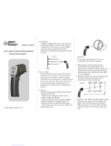
How to obtain Emissivity?
In the EMS mode, press and hold the Laser/Backlight
button until the “EMS” icon on the left side of LCD
blinking. At this time, “ε= --” will appear at the upper
side of the LCD; IR temperature value will be in the
middle of LCD; and Type K temperature value is at the
lower side of the LCD.
Contact the Type K probe to the object surface and test
the temperature of same point with IR measurement.
After both values are stable, press UP or DOWN button
for confirmation. Then, emissivity of the object will be
shown at the upper side of the LCD.
Press MODE button or trigger to enter normal
measurement.
Note:
1. When the IR value is not corresponding to the TK
value, or IR and TK tested the different points, no
emissivity will be obtainable or a wrong emissivity
will be obtained.
2. The temperature of the target should be higher than
the environment temperature. Normally, 100℃ is

- -
14
suitable for obtaining a higher accuracy emissivity.
After obtaining the emissivity, if the difference
between IR value (in the middle of LCD) and TK
value (at the lower side of LCD) is too big, the
obtained emissivity will be incorrect. It’s necessary
to obtain a new emissivity.
Note: Measurement considerations
Holding the meter by its handle, point
the IR Sensor toward the object
whose temperature is to be measured.
The meter automatically compensates
for temperature deviations from
ambient temperature. Keep in mind
that it will take up to 30 minutes to
adjust to wide ambient temperatures are to be
measured followed by high temperature measurements,
some time (several minutes) is required after the low
(and before the high) temperature measurements are
made.
This is a result of the cooling process, which must take
place for the IR sensor.

- -
15
7. BATTERY REPLACEMENT
① As battery power is not sufficient, LCD will display
“ ” replacement with one new 9V battery is
required.
② Open battery cover, then take out the battery from
instrument and replace with a new 9-Volt battery
and place the battery cover back.
8. NOTES:
How it Works
Infrared thermometers measure the surface
temperature of an object. The unit’s optics sense
emitted, reflected, and transmitted energy, which is
collected and focused onto a detector. The unit’s
electronics translate the information into a temperature
reading, which is display on the unit. In units with a
laser, the laser is used for aiming purposes only.
Field of View
Make sure that the target is larger than the unit’s spot
size. The smaller the target, the closer you should be to
it. When accuracy is critical, make sure the target is at
least twice as large as the spot size.

- -
16
Distance & Spot Size
As the distance (D) from the object increases, the spot
size (S) of the area measured by the unit becomes
larger. See: Fig: 1.
Locating a hot Spot
To find a hot spot aim the thermometer outside the area
of interest, then scan across with an up and down
motion until you locate hot spot.
Reminders
① Not recommended for use in measuring shiny or
polished metal surfaces ( stainless steel, aluminum,
etc.).See Emissivity

- -
17
② The unit cannot measure through transparent surfaces
such as glass. It will measure the surface temperature of
the glass instead.
③Steam, dust, smoke, etc., Can prevent accurate
measurement by obstructing the unit’s optics.
Emissivity
Emissivity is a term used to describe the
energy-emitting characteristics of materials.
Most (90% of typical applications) organic materials
and painted or oxidized surfaces have an emissivity of
0.95 (pre-set in the unit). Inaccurate readings will result
from measuring shiny or polished metal surfaces. To
compensate, cove the surface to be measured with
masking tape or flat black paint. Allow time for the tape
to reach the same temperature as the material
underneath it. Measure the temperature of the tape or
painted surface.
Emissivity Values

- -
18
Substance Thermal
emissivity
Substance Thermal
emissivity
Asphalt 0.90 to
0.98
Cloth (black) 0.98
Concrete 0.94 Human skin
0.98
Cement 0.96 Lather 0.75 to
0.80
Sand 0.90 Charcoal
(powder)
0.96
Earth 0.92 to
0.96
Lacquer 0.80 to
0.95
Water 0.92 to
0.96
Lacquer
(matt)
0.97
Ice 0.96 to
0.98
Rubber
(black)
0.94
Snow 0.83 Plastic 0.85 to
0.95
Glass 0.90 to
0.95
Timber 0.90
Ceramic 0.90 to Paper 0.70 to
0.94

- -
19
Marble 0.94 Chromium
oxides
0.81
Plaster 0.80 to
0.90
Copper
oxides
0.78
Mortar 0.89 to
0.91
Iron oxides 0.78 to
0.82
Brick 0.93 to
0.96
Textiles 0.90
9. MAINTENANCE & CLEARING:
Repairs or serving aren’t covered in this manual
should only be performed by qualified personnel.
Periodically wipe the case with a dry cloth. Don’t use
abrasives or solvents on this instrument.
When serving, use only specified replacement parts.
/