January 1, 2022
Lit. No. 78694EN, Rev. 00
This manual supersedes all editions with an earlier date.
HD UTV V-Plow &
HD UTV Straight Blade Snowplow
Blade Assembly 74360, 84930
Attachment Assembly 77860, 77865
Owner's Manual
Original Instructions
Western Products, PO Box 245038, Milwaukee, WI 53224-9538 • www.westernplows.com
A DIVISION OF DOUGLAS DYNAMICS, LLC
CAUTION
Read this document before operating or
servicing snowplow.


Lit. No. 78694EN, Rev. 00 3 January 1, 2022
OWNER INFORMATION
Register your snowplow online at www.westernplows.com
Owner Name: ______________________________________________________________________________
Date Purchased: ____________________________________________________________________________
Dealer Name: ______________________________________________ Phone: _________________________
Dealer Address: _____________________________________________________________________________
Vehicle Model/Year: _________________________________________________________________________
Snowplow Model/Year: _______________________________________________________________________
Snowplow Type/Size: ______________________________________________ Weight: ______________ lb/kg
Ballast: No ___ Yes ___ Amount: ___________lb/kg
Hydraulic Unit Serial Number: __________________________________________________________________
Blade Serial Number: ________________________________________________________________________
Translated Owner's Manuals can be found online at
https://library.westernplows.com/default.asp?cat=1257

Lit. No. 78694EN/78695EN, Rev. 00 4 January 1, 2022

Lit. No. 78694EN/78695EN, Rev. 00 5 January 1, 2022
TABLE OF CONTENTS
SAFETY ..................................................................... 7
Safety Denitions .................................................. 7
Warning/Caution & Instruction Labels .................. 7
UTV V-Plow Snowplow .................................. 7
UTV Straight Blade.........................................8
Translation of Safety Labels ........................... 9
Safety Precautions .............................................. 10
Hydraulic Safety .................................................. 10
Fuses .................................................................. 10
Personal Safety................................................... 11
Fire and Explosion .............................................. 11
Cell Phones ......................................................... 11
Ventilation ........................................................... 11
Battery Safety ..................................................... 11
Noise ................................................................... 11
Vibration .............................................................. 11
GETTING TO KNOW YOUR SNOWPLOW .......... 12
Snowplow Components ...................................... 12
Vehicle Mount Kit ................................................ 12
Hydraulic Unit ...................................................... 13
Controls ............................................................... 13
MOUNTING SNOWPLOW TO VEHICLE .............. 14
Attaching the Snowplow ..................................... 14
OPERATING YOUR SNOWPLOW ........................ 15
Hand-Held Control .............................................. 15
Joystick Control................................................... 17
SECURITY GUARD™ System Operation .......... 20
Smooth Stop ....................................................... 22
One -Touch FLOAT ..............................................22
Blade Positions ...................................................23
UTV V-Plow Snowplow ................................ 23
UTV Straight Blade Snowplow ..................... 24
Blade Drop Speed Adjustment ........................... 25
Transporting the Snowplow ................................ 26
Driving and Plowing on Snow and Ice ................ 26
Plowing Snow ..................................................... 27
Parking with Snowplow Attached .......................28
Towing Disabled or Stuck Vehicles ..................... 28
Checking Hydraulic Fluid Level ........................... 28
DETACHING SNOWPLOW FROM VEHICLE ...... 29
Detaching the Snowplow .................................... 29
MAINTENANCE ...................................................... 30
Preseason Check................................................30
In-Season Maintenance ......................................30
Postseason Maintenance.................................... 31
Storage ............................................................... 31
Hydraulic System ................................................ 32
Annual Fluid Change .................................... 32
Hose or Fitting Removal ............................... 33
Hose or Fitting Installation ............................33
Fuse Replacement .............................................. 34
Vehicle ................................................................34
Recycle ...............................................................34
Emergency Parts/Tools ......................................34
SPECIFICATIONS ...................................................35
Snowplow Weight ...............................................35
Hydraulic Units: Pump Motor Specications .......35

Lit. No. 78694EN/78695EN, Rev. 00 6 January 1, 2022
This manual has been prepared to acquaint you with
the safety information, operation, and maintenance of
your new snowplow. Please read this manual carefully
and follow all recommendations.
Before installing a snowplow, make sure your vehicle
is equipped with our recommended options for plowing
snow. This will help ensure trouble-free operation of
your snowplow. Keep this manual accessible. It is a
handy reference in case minor service is required.
PREFACE
When service is necessary, bring your snowplow to
your local outlet. They know your snowplow best and
are interested in your complete satisfaction.
The illustrations found in this manual represent
typical components. They may not match your exact
installation.

Lit. No. 78694EN/78695EN, Rev. 00 7 January 1, 2022
SAFETY
Instruction Label
SAFETY
SAFETY DEFINITIONS
NOTE: Indicates a situation or action that can lead
to damage to your snowplow and vehicle or other
property. Other useful information can also be
described.
CAUTION
Indicates a potentially hazardous situation
that, if not avoided, may result in minor or
moderate injury. It may also be used to alert
against unsafe practices.
WARNING/CAUTION & INSTRUCTION
LABELS
UTV V-Plow Snowplow
Become familiar with and inform users about the
warning/caution, serial number, and instruction labels
on the back of the blade.
NOTE: If labels are missing or cannot be read, see
your sales outlet.
WARNING
Indicates a potentially hazardous situation
that, if not avoided, could result in death or
serious personal injury.
Serial Number Label
Serial No.
Code Denition
YY 2-Digit Year
MM 2-Digit Month
DD 2-Digit Day
LL 2-Digit Location Code
XXXX 4-Digit Sequential Number
ZZZZZZ 5- to 7-Digit Blade Assembly PN
YYMMDDLLXXXXZZZZZ
ZZZZZ
zzzzz YYMMDDLLXXXXZZZZZ
Warning/Caution Label

Lit. No. 78694EN/78695EN, Rev. 00 8 January 1, 2022
SAFETY
UTV Straight Blade
Become familiar with and inform users about the
warning/caution, serial number, and instruction labels
on the back of the blade.
NOTE: If labels are missing or cannot be read, see
your sales outlet.
Serial Number Label
Warning/Caution Label
Instruction Label
Serial No.
Code Denition
YY 2-Digit Year
MM 2-Digit Month
DD 2-Digit Day
LL 2-Digit Location Code
XXXX 4-Digit Sequential Number
ZZZZZZ 5- to 7-Digit Blade Assembly PN

Lit. No. 78694EN/78695EN, Rev. 00 9 January 1, 2022
SAFETY
Translation of Safety Labels
Label Translation of Label Text
WARNING
Blade could drop unexpectedly, crushing or trapping limbs. Lower blade when vehicle is
parked.
Overloading could negatively aect vehicle handling. To avoid serious injury or death, do
not exceed maximum vehicle load capacity, including blade and ballast.
CAUTION
Read Owner's Manual before operating or servicing the snowplow.
Transport speed should not exceed 20 mph (32 km/h). Further reduce speed under
adverse travel conditions.
Plowing speed should not exceed 10 mph (16 km/h).
See your sales outlet/website for specic vehicle application recommendations.
ATTACH
1. Slowly drive vehicle forward to engage rear receiver pins into headgear slots. Apply
vehicle parking brake.
2. Hold down lock lever and move hitch pin handle out of the handle lock notch,
allowing spring to move the hitch pin handle foward.
3. Plug into electrical harness.
4. Turn plow control in vehicle ON and activate FLOAT.
5. Stand in front of blade. Push top of headgear toward vehicle to allow hitch pins to
fully engage hitch pin holes.
6. Verify the lock pin is engaged in the forward hole in the lock pin bracket.
7. Remove hairpin, adjustment pin, and stand.
DETACH
1. With blade straight, lower snowplow to the ground. Activate FLOAT, then turn plow
control in vehicle OFF. Apply vehicle parking brake.
2. Unplug electrical harness.
3. Insert stand through slot in the passenger side headgear horn. Adjust stand as far
down as possible, install adjustment pin, and secure with a hairpin.
4. Hold down lock lever to disengage the lock pin and move the hitch pin handle
rearward to fully disengage hitch pins from receivers.
5. Move hitch pin handle into handle lock notch.
WARNING
Keep ngers away from snowplow and UTV attachment points.
Read Owner's Manual for complete instructions.

Lit. No. 78694EN/78695EN, Rev. 00 10 January 1, 2022
SAFETY
WARNING
Do not exceed GVWR, GAWR, or
maximum vehicle load capacity,
including the blade and ballast.
HYDRAULIC SAFETY
• Always inspect hydraulic components and hoses
before using. Replace any damaged or worn parts
immediately.
• If you suspect a hose leak, DO NOT use your hand
to locate it. Use a piece of cardboard or wood.
FUSES
The electrical and hydraulic systems contain several
blade-style automotive fuses. If a problem should
occur and fuse replacement is necessary, the
replacement fuse must be of the same type and
amperage rating as the original. Installing a fuse with
a higher rating can damage the system and could start
a re. Fuse replacement information, including fuse
ratings and locations, is located in the Maintenance
section of this Owner's Manual.
SAFETY PRECAUTIONS
Follow all safety and operating instructions in
your UTV owner's manual.
Improper installation and operation could cause
personal injury, and/or equipment and property damage.
Read and understand labels and this Owner's Manual
before installing, operating, or making adjustments.
WARNING
Lower the blade when the vehicle is parked.
Temperature changes could change
hydraulic pressure, causing the blade to
drop unexpectedly or damaging hydraulic
components. Failure to do this could result in
serious personal injury.
WARNING
Remove blade assembly before placing
vehicle on hoist.
WARNING
The driver shall keep bystanders clear of the
blade when it is being raised, lowered, or
angled. Do not stand between the vehicle and
the blade or within 8 feet (2.4 m) of a moving
blade. A moving or falling blade could cause
personal injury.
WARNING
To prevent accidental movement of the blade,
always turn the control OFF whenever the
snowplow is not in use. The power indicator
light will turn OFF.
WARNING
Keep hands and feet clear of the blade and
T-frame when mounting or removing the
snowplow. Moving or falling assemblies could
cause personal injury.
WARNING
Hydraulic uid under pressure can
cause skin injection injury. If you are
injured by hydraulic uid, get medical
attention immediately.
WARNING
Vehicle mount reduces ground clearance. Use
additional caution when driving vehicle with
mount installed. Remove vehicle mount to
restore original vehicle ground clearance at
the end of the plowing season.

Lit. No. 78694EN/78695EN, Rev. 00 11 January 1, 2022
SAFETY
VENTILATION
BATTERY SAFETY
NOISE
Airborne noise emission during use is below 95 dB(A)
for the snowplow operator.
VIBR ATION
Operating snowplow vibration does not exceed 2.5 m/s2
to the hand-arm or 0.5 m/s2 to the whole body.
PERSONAL SAFETY
• Remove the ignition key and put the vehicle in
PARK or in gear to prevent others from starting
the vehicle during installation or service.
• Wear only snug-tting clothing while working on
your vehicle or snowplow.
• Do not wear jewelry or a necktie, and secure
long hair.
• Wear safety goggles to protect your eyes from
battery acid, gasoline, dirt, and dust.
• Wear hearing protection such as earmus or
earplugs as appropriate or required.
• Avoid touching hot surfaces such as the engine,
radiator, hoses, and exhaust pipes.
• Always have a re extinguisher rated BC handy for
ammable liquids and electrical res.
FIRE AND EXPLOSION
Be careful when using gasoline. Do not use gasoline
to clean parts. Store only in approved containers away
from sources of heat or ame.
CELL PHONES
A driver's rst responsibility is the safe operation of
the vehicle. The most important thing you can do
to prevent a crash is to avoid distractions and pay
attention to the surroundings. Wait until it is safe
to operate mobile communication equipment such
as cell phones, text messaging devices, pagers, or
two-way radios.
CAUTION
Batteries normally produce explosive gases
which can cause personal injury. Therefore,
do not allow ames, sparks, or lit tobacco
to come near the battery. When charging or
working near a battery, always cover your
face and protect your eyes, and also provide
ventilation.
• Batteries contain sulfuric acid, which burns
skin, eyes, and clothing.
• Disconnect the battery before removing or
replacing any electrical components.
WARNING
Vehicle exhaust contains lethal fumes.
Breathing these fumes, even in low
concentrations, can cause death. Never
operate a vehicle in an enclosed area without
venting exhaust to the outside.
WARNING
Gasoline is highly ammable and gasoline
vapor is explosive. Never smoke while
working on vehicle. Keep all open ames
away from gasoline tank and lines. Wipe up
any spilled gasoline immediately.

Lit. No. 78694EN/78695EN, Rev. 00 12 January 1, 2022
GETTING TO KNOW YOUR SNOWPLOW
GETTING TO KNOW YOUR SNOWPLOW
SNOWPLOW COMPONENTS
A snowplow consists of all the components that are
readily removable from the vehicle as a unit. This
includes the blade, A-frame or T-frame, headgear,
and hydraulic unit. The snowplow is ready and easy to
mount when you need to plow snow. When plowing is
completed, remove the snowplow.
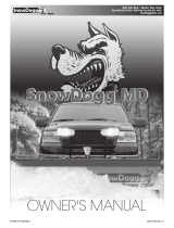
T-Frame to Blade Assembly
Determine whether to use the inside or outside angle
ram holes, depending on the width of the UTV. If the
UTV width exceeds 60" (152 cm), attach the angle
rams to the outer blade holes. The snowplow width
is to be equal to or greater than the width of the UTV.
Align the holes in the rod end of the angle ram with the
corresponding holes on the back of the blade.
Install a 1/2" x 2-7/8" clevis pin or 1/2" x 4" Grade 8
cap screw (provided in the parts bag) from the top
down to attach each rod. Secure the clevis pins with
5/32" x 1-1/2" cotter pins, and secure the cap screws
with 1/2" locknuts.
VEHICLE MOUNT KIT
Mount kits have been designed for most UTVs. Due to
the dierences among vehicle models, the kits are not
interchangeable.
The vehicle mount assembly is bolted to the underside
of the vehicle frame, and the receiver assembly is
attached to the vehicle mount. It is engineered to
provide the primary connecting points between the
snowplow assembly and the vehicle. The weight of the
snowplow system is distributed to the frame of your
vehicle by the mount assembly.
WARNING
Vehicle mount reduces ground clearance. Use
additional caution when driving vehicle with
mount installed. Remove vehicle mount to
restore original vehicle ground clearance at
the end of the plowing season.
Blade
Hitch Pin
Stand
Lift Ram
Headgear
Blade
Guide
Receiver
Trip Spring
T-Frame
Hydraulic Unit
and Cover
Cutting
Edge
Angle
Ram
Cotter
Pin
Inside Hole =
5' (1.54 m)
Width in Vee
Outer Hole =
5-1/2' (1.68 m) Width
in Vee
Clevis
Pin
Pivot Pin

Lit. No. 78694EN/78695EN, Rev. 00 13 January 1, 2022
GETTING TO KNOW YOUR SNOWPLOW
CONTROLS
The vehicle ignition (key) switch controls a fused
circuit that powers the control directly from the battery.
The control is backlit, which will illuminate when the
vehicle is turned to ACC or ON.
The ON/OFF button/switch on the cab control allows
you to turn OFF the control and prevent blade
movement even when the ignition switch is ON.
The ON/OFF switch serves as an emergency stop
when required.
HYDRAULIC UNIT
The hydraulic system gives you full control of the
snowplow from the driver's seat. On the V-plow, two
double-acting hydraulic rams hold the wings at the
desired angles.
The hydraulic unit's manifold has built-in blade scrape
lock circuitry. This feature resists the tendency of a
snowplow to "oat up" when large amounts of snow
build up in front of the blade while plowing deep snow
or stacking snow into piles.
The scrape lock feature is factory set. See your sales
outlet for adjustment.
WARNING
To prevent accidental movement of the blade,
always turn the control OFF whenever the
snowplow is not in use. The power indicator
light will turn OFF.
Straight Blade Hydraulic Unit
Motor
Breather/Fill Plug Quill
Drain Plug
Reservoir
Valve Manifold
V-Plow Hydraulic Unit
Motor
Breather/Fill Plug
Quill
Drain Plug
Reservoir
Valve Manifold
Joystick Control
Hand-Held Control Power Indicator
Light (red)
Power
Indicator
Light (red)
ON/OFF Switch
(emergency stop)
ON/OFF Switch
(emergency stop)

Lit. No. 78694EN/78695EN, Rev. 00 14 January 1, 2022
MOUNTING SNOWPLOW TO VEHICLE
2. Hold down the lock lever and move the hitch pin
handle out of the handle lock notch, allowing the
spring to move the hitch pin handle forward.
3. Plug in the electrical harness.
4. Turn the plow control ON and activate FLOAT.
5. Stand in front of the blade. Push the top of the
headgear toward the vehicle to allow the hitch pins
to fully engage the hitch pin holes.
6. Verify that the lock pin is engaged in the forward
hole in the lock pin bracket.
7. Remove the hairpin, adjustment pin, and stand.
MOUNTING SNOWPLOW TO VEHICLE
ATTACHING THE SNOWPLOW
NOTE: For V-plow snowplows, the blade must be
in the retracted (vee) position when attaching or
detaching the snowplow.
NOTE: Use dielectric grease to prevent corrosion
on all connections.
NOTE: Use lubricant on connecting pins to ensure
ease of attach/detach.
1. Slowly drive the vehicle forward to engage the
rear receiver pins into the headgear slots. Apply
the vehicle parking brake.
WARNING
Inspect snowplow components and fasteners
for wear or damage whenever attaching or
detaching the snowplow. Worn or damaged
components could allow the snowplow to
drop unexpectedly.
WARNING
Keep 8' (2.4 m) clear of the blade when it is
being raised, lowered, or angled. Do not stand
between vehicle and blade or directly in front
of the blade. If the blade hits or drops on you,
you could be seriously injured.
WARNING
Keep ngers away from snowplow and UTV
attachment points.
Rear
Receiver
Pin
Headgear
Slot
Adjustment
Pin
Lock Pin Bracket
Handle
Lock Notch
Lock
Lever
Lock Pin
Stand
Hitch Pin
Handle
Hairpin

Lit. No. 78694EN/78695EN, Rev. 00 15 January 1, 2022
OPERATING YOUR SNOWPLOW
HAND-HELD CONTROL
1. Turn the vehicle ignition switch to the "ON" or
"ACCESSORY" position. The control backlight will
illuminate.
2. Press the ON/OFF button on the control. The
power indicator light glows red, indicating that the
control is ON. The power indicator light glows red
whenever the control and vehicle ignition switch
are both ON and the electrical connections to the
snowplow are completed.
The ON/OFF button operates as an emergency
stop, if required.
Function Time-Outs
All control functions, except LOWER/FLOAT, time
out (stop) automatically after a period of time. This
is to limit the amount of electrical energy required
from the vehicle. The time-outs are written into the
programming and vary by snowplow model.
NOTE: If a control function times out before the
desired blade movement is complete, release the
button and press it again.
OPERATING YOUR SNOWPLOW
WARNING
To prevent accidental movement of the blade,
always push the ON/OFF button to switch the
control OFF whenever the snowplow is not in
use. The power indicator light will turn OFF.
Automatic Shutdown
The control will automatically turn OFF after being
idle for 20 minutes. To reactivate the control after a
shutdown, press the ON/OFF button.
Smooth Stop
The control automatically allows the blade to coast
to a stop when a control button is released. This
results in smoother operation, reduces the shock to
the hydraulic system, and increases hose and valve
life. See "Smooth Stop" later in this section for more
information.
Hand-Held Control Functions
Raise, Lower, Float, Angle
The four diamond-shaped buttons in the center of the
control face, when pressed, will result in the blade
movements described in the following table.
Function Description of Operation
RAISE Press this button to raise the blade and cancel
the FLOAT mode.
LOWER Press this button to lower the blade. Release
the button to stop blade at the desired height.
FLOAT†
Press the LOWER button and hold 3/4 second
to activate this mode. The FLOAT light in
the upper left corner of the control face will
illuminate. The blade will lower to the ground
surface and follow the contour of the surface
as it dips or rises. This function does not
time out, but the control will shut down after
20 minutes of nonuse.
Press the RAISE button momentarily to
cancel FLOAT. Angling left or right will not
interrupt (pause) the FLOAT function.
L
(Angle
Left)
With wings in a straight line, press the
L button to move both wings to the angle left
position. The left wing retracts while the right
wing extends.
R
(Angle
Right)
With wings in a straight line, press the
R button to move both wings to the angle right
position. The right wing retracts while the left
wing extends.
† FLOAT mode activates immediately when the one-touch FLOAT
feature is enabled. See "One-Touch FLOAT" later in this section
for more information.
RAISE
LOWER
RL
ON/OFFFLOAT
1
3
2
4
S
C
O
O
P
R
E
T
R
A
C
T
W
I
N
G
W
I
N
G
FLOAT Light
(green)
ON/OFF Button
(emergency stop)
Power Indicator
Light (red)

Lit. No. 78694EN/78695EN, Rev. 00 16 January 1, 2022
OPERATING YOUR SNOWPLOW
Wing Positions: V-Plow Only
The two round buttons located to the left and right of
the LOWER button move either wing independently of
the other as described in the following table.
Function Description of Operation
L WING
Press this button on the left side of the control
to move the left wing. The rst time the button
is pressed after the control is turned ON or
another function is used, the wing will extend.
Repeated use of the same button without
using another function results in movement
in the opposite direction from the previous
movement.
R WING
Press this button on the right side of the
control to move the right wing. The rst time
the button is pressed after the control is
turned ON or another function is used, the
wing will extend. Repeated use of the same
button without using another function results in
movement in the opposite direction from the
previous movement.
NOTE: If a control function times out before the
desired blade movement is complete, release the
button and press it again.
SECURITY GUARD™ System (1, 2, 3, 4)
The four round buttons located to the left and
right of the LOWER and RAISE buttons will also
operate the SECURITY GUARD system. See
"SECURITY GUARD System" later in this section for
more information.
Scoop/Retract Blade Position: V-Plow Only
The two round buttons located to the left and right of
the RAISE button move both wings at the same time
into the blade positions described in the following
table.
Function Description of Operation
SCOOP Press this button to extend both wings forward
into the scoop position.
RETRACT Press this button to draw both wings into the
fully retracted/vee position.
RAISE
ON/OFFFLOAT
12
S
C
O
O
P
R
E
T
R
A
C
T
LOWER
RL
34
W
I
N
G
W
I
N
G

Lit. No. 78694EN/78695EN, Rev. 00 17 January 1, 2022
OPERATING YOUR SNOWPLOW
JOYSTICK CONTROL
1. Turn the vehicle ignition switch to the "ON" or
"ACCESSORY" position. The control backlight will
illuminate.
2. Move the ON/OFF switch on the side of the
control to the "ON" position. The power indicator
light glows red, indicating that the control is ON.
The indicator light glows red whenever the control
and the vehicle ignition switch are both ON and
the electrical connections to the snowplow are
completed.
The ON/OFF switch operates as an emergency
stop if required.
WARNING
To prevent accidental movement of the blade,
always move the ON/OFF switch to OFF
whenever the snowplow is not in use. The
power indicator light will turn OFF.
Function Time-Outs
All control functions, except LOWER/FLOAT, time
out (stop) automatically after a period of time. This
is to limit the amount of electrical energy required
from the vehicle. The time-outs are written into the
programming and vary by snowplow model.
NOTE: If a control function times out before the
desired blade movement is complete, release the
lever to the center position, then move it back into
the desired function.
Automatic Shutdown
The control will automatically turn OFF after being
idle for 20 minutes. To reactivate the control after a
shutdown, move the ON/OFF switch to OFF, then
back to ON.
Smooth Stop
The control automatically allows the blade to coast to
a stop when the lever returns to center position. This
results in smoother operation, reduces the shock to
the hydraulic system, and increases hose and valve
life. See "Smooth Stop" later in this section for more
information.
Control Lever Movement
From the center position, the control lever can be
moved in one of eight directions to control various
movements of the snowplow blade. To change from
one movement of the blade to another, the control
lever must be moved back to the center position
before selecting the desired function. Whenever the
lever is released, it should spring back into the center
position to stop any blade movement.
34
21
L R
RAISE
LOWER
ON/OFF FLOAT
SCOOPRETRACT
WING WING
ON/OFF Button
(emergency stop)
Power Indicator
Light (red)

Lit. No. 78694EN/78695EN, Rev. 00 18 January 1, 2022
OPERATING YOUR SNOWPLOW
Function Description of Operation
L
(Angle
Left)
With wings in a straight line, move the control
lever straight to the left to move both wings to
the angle left position. The left wing retracts
while the right wing extends.
R
(Angle
Right)
With wings in a straight line, move the control
lever straight to the right to move both wings
to the angle right position. The right wing
retracts while the left wing extends.
† FLOAT mode activates immediately when the one-touch FLOAT
feature is enabled. See "One-Touch FLOAT" later in this section
for more information.
Scoop/Retract Blade Position: V-Plow Only
Moving the control lever from the center position
toward the word SCOOP or RETRACT on the face of
the control body will cause both wings to move at the
same time into the following blade positions.
Function Description of Operation
SCOOP
Move the control lever toward the word
SCOOP on the control face to extend both
wings forward into the scoop position.
RETRACT
Move the control lever toward the word
RETRACT on the control face to draw both
wings into the fully retracted/vee position.
Joystick Control Functions
Raise, Lower, Float, Angle
Moving the control lever straight up and down or from
side to side on the control body will result in the blade
movements described in the following tables.
Function Description of Operation
RAISE
Move the control lever toward the top of the
control body to raise the blade and cancel
FLOAT mode.
LOWER
Move the control lever toward the bottom
of the control body to lower the snowplow.
Release the lever to stop blade at desired
height.
FLOAT†
Move the control lever to the LOWER position
and hold 3/4 second to activate this mode.
The FLOAT light in the upper right corner of
the control face will illuminate. The blade will
lower to the ground surface and follow the
contour of the surface as it dips or rises. This
function does not time out, but the control will
shut down after 20 minutes of nonuse.
Move the lever to the RAISE position
momentarily to cancel FLOAT. Angling left
or right will not interrupt (pause) the FLOAT
function.
34
21
L R
RAISE
LOWER
ON/OFF FLOAT
SCOOPRETRACT
WING WING
34
21
L R
RAISE
LOWER
ON/OFF FLOAT
SCOOPRETRACT
WING WING
FLOAT Light
(green)

Lit. No. 78694EN/78695EN, Rev. 00 19 January 1, 2022
OPERATING YOUR SNOWPLOW
Wing Positions: V-Plow Only
Moving the control lever from the center position
toward the word WING on either side of the face
of the control body will cause either wing to move
independently of the other, as described in the
following table.
Function Description of Operation
L WING
Move the control lever toward the left side
of LOWER on the control face to move the
left wing. The rst time the lever is moved
into the slot after the control is turned ON
or another function is used, the wing will
extend. Repeated use of the lever in the same
slot without using another function results in
movement in the opposite direction from the
previous movement.
R WING
Move the control lever toward the right side
of LOWER on the control face to move the
right wing. The rst time the lever is moved
into the slot after the control is turned ON or
another function is used, the wing will extend.
Repeated use of the lever in the same slot
without using another function results in
movement in the opposite direction from the
previous movement.
NOTE: If a control function times out before the
desired blade movement is complete, release the
lever to the center position, then move it back into
the desired function.
SECURITY GUARD™ System (1, 2, 3, 4)
Moving the control lever from the center position
toward any of the four digits on the face of the control
will also operate the SECURITY GUARD system. See
"SECURITY GUARD System Operation" later in this
section for more information.
34
21
L R
RAISE
LOWER
ON/OFF FLOAT
SCOOPRETRACT
WING WING

Lit. No. 78694EN/78695EN, Rev. 00 20 January 1, 2022
OPERATING YOUR SNOWPLOW
SECURITY GUARD™ SYSTEM
OPERATION
Activation & Establishing a
4-Digit Security Code
NOTE: The snowplow must be attached to the
vehicle, and all the electrical connections must
be connected prior to activating the security code
function.
The SECURITY GUARD feature was developed as
an electrical anti-theft system. The system provides
a deterrent against theft and/or non-permitted use
by allowing you to electronically lock the snowplow's
hydraulic functions.
All multiplex snowplow controls come equipped with
the SECURITY GUARD system. To use this function,
you must complete the activation process.
1. Turn the vehicle ignition switch to the "ON" or
"ACCESSORY" position. The control backlight will
illuminate. (It is not necessary to start the vehicle.)
2. Verify that the control power indicator is OFF. If
the power indicator light is red, the control is ON.
Move the ON/OFF switch to "OFF" or push the
ON/OFF button to turn the control OFF.
3. To activate the SECURITY GUARD mode, move
the control lever to the #1 position or press the
#1 button four consecutive times, and then move the
lever to the #4 position or press the #4 button four
consecutive times (sequence: 1, 1, 1, 1, 4, 4, 4, 4).
The green FLOAT light will ash quickly and the
red power indicator light will turn ON, indicating
that the system is ready to accept your 4-digit
security code.
Enter your 4-digit security code by moving the
control lever to (or pressing the button for) any four
of the eight following positions: UP, DOWN, LEFT,
RIGHT, 1, 2, 3, or 4.
Once you have entered your 4-digit security code,
the FLOAT light will stop ashing and The power
indicator light will turn OFF. This indicates that
your 4-digit security code is entered and stored in
the SECURITY GUARD system.
4. Once a 4-digit security code is established, the
SECURITY GUARD system will recognize any
control that has been programmed with the same
4-digit security code. Any control not programmed
with the correct 4-digit security code will require
the user to enter the established security code
before activating the snowplow (see the Manual
Unlock procedure below).
NOTE: If the control is turned ON prior to
completing the programming procedure, your
4-digit security code will be cancelled.
Manual Unlock
If the SECURITY GUARD system is activated and you
are using a control with a dierent 4-digit code than
the established security code, you will be required
to manually enter the 4-digit security code before
operating a locked snowplow.
1. Turn the vehicle ignition switch to the "ON" or
"ACCESSORY" position. The control backlight will
illuminate.
2. Move the ON/OFF switch to the "ON" position or
push the ON/OFF button to switch the control ON.
3. The power indicator light will ash rapidly,
indicating that the snowplow is locked.
4. Enter the 4-digit security code.
5. After the correct security code is entered, the
power indicator light will change from ashing
rapidly to a solid light to indicate that the snowplow
has been successfully unlocked.
NOTE: If the snowplow/vehicle electrical
connection is lost or disconnected, the
SECURITY GUARD system will reset, requiring
any control that is not programmed with the
established 4-digit security code to manually
re-enter the security code to activate the
snowplow.
Page is loading ...
Page is loading ...
Page is loading ...
Page is loading ...
Page is loading ...
Page is loading ...
Page is loading ...
Page is loading ...
Page is loading ...
Page is loading ...
Page is loading ...
Page is loading ...
Page is loading ...
Page is loading ...
Page is loading ...
Page is loading ...
/