
5) Once the stopper has been inflated remove the red
inflation line.
• WARNING – Over-inflated stoppers can burst, potentially
causing serious accidents
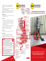
8. INFLATION USING 12V COMPRESSOR OR HAND PUMP
WITH PRESSURE RELIEF VALVE
1) Connect the male coupling on the hand pump or
compressor hose to the female coupling on the pressure
relief valve (A).
2) Connect the female coupling on the red inflation line to
the male coupling on the pressure relief valve (B).
3) Connect the male coupling on the red inflation line to the
female coupling on the pipe stopper.
4) Inflate the stopper using the 12V Compressor or Hand
Pump, the pressure relief valve will activate at 1.5 bar.
5) Once the stopper has been inflated remove the red
inflation line.
• ALWAYS – Use the MGF-supplied pressure relief valve
• WARNING – Over-inflated stoppers can burst, potentially
causing serious accidents
9. BRACING
• WARNING – All stoppers must be braced, failure to do so
could result in damage, serious injury or death
10. AIR TESTING
• Bypass stopper may also be used to conduct an air test.
• MGF can supply a testing plate that attached to the bauer
fitting on the stopper, and a ‘U’ Gauge for conducting the
test.
1) Connect the red inflation line male coupling into either
of the female couplings situated in the centre of the testing
plate.
2) Before internal pressure is applied place the ‘U’ gauge
hose into the left-hand connector on the ‘U’ gauge and
connect the free end of the hose into the free female
coupling in the centre of the plate.
3) Fill the ‘U’ gauge to approx. ¾ level by pouring clean
water into the open end of the ‘U’ gauge assembly and sit
firmly on a flat area or push the pointed base into
soft ground to secure upright.
1. IMPORTANT NOTES
• For the use of MGF supplied equipment only.
• Ensure potential users are fully trained in the operation of
this equipment and a site specific safe system of work is in
place and adhered to.
• It is essential that site specific risk assessments are
undertaken.
• If in doubt concerning the integrity of any part of the
equipment DO NOT USE IT.
• Ensure the correct stopper has been supplied for size of the
pipe, an over-stretched stopper can burst.
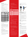
• Before using a stopper, it is necessary to establish the
maximum back pressure it will need to withstand. Back
pressure can be very high as seen form the table below:
2. MGF EXAMINATION AND TESTING
• Upon return to MGF the equipment will be cleaned,
inspected and function tested by a competent and trained
MGF safety technician.
3. VISUAL INSPECTION/FUNCTIONAL TEST - PRIOR TO USE
• Before the start of each use ensure that the equipment is
clean and free from debris and there are no obvious defects.
• Ensure that the item has a green tag, stating when it was
last inspected.
• Each item comes with a unique ID number, please ensure
this can be found.
4. VETTER BYPASS PIPE STOPPER
• You have been supplied with a durable expandable pipe
stopper designed to be inflated in a round pipe and, when
suitable braced, to withstand a maximum back pressure of
0.5 bar.
• Bauer couplings allow rigid or lay flat hose to be connected
to the stopper, taking the flow above ground via a pump or
by gravity through the area of work.
mgf.co.uk
• You have also been supplied with:
- A hand pump or 12V compressor
- A pressure relief valve (max pressure 1.5 bar)
- Red 10m inflation line with male/female couplings
OR
- Compressor controller
- Red 10m inflation line with male/female couplings
• It is also possible to inflate a stopper from an air cylinder
5. SIZE RANGE
6. BEFORE INFLATION
• Before installation of a stopper the internal surface of the
pipe should be cleaned of all debris from the area where the
stopper will be situated.
• Make sure there are no protrusions that could damage the
stopper.
• It is advisable that a small security line should be attached
to the stopper and tied off to prevent the possible loss of the
stopper during deflation.
• Before use, check diameter of the pipe to make sure it does
not exceed the maximum diameter of the stopper.
• NEVER – Inflate stoppers over sharp protrusions
• ALWAYS – Clean area of pipe to receive stopper
• ALWAYS – Check the diameter of the pipe before use, to
ensure it does not exceed the maximum diameter of the
stopper
7. INFLATION USING COMPRESSOR CONTROLLER
• The compressor controller is equipped with a standard claw
coupling that will fit into any building site compressor line.
• It contains a safety relief valve to eliminate the possibility of
over inflation of the stopper.
1) Connect air supply to claw (A).
2) Connect male coupling (B) to the female coupling on the
red inflation line.
3) Connect the male coupling on the red inflation line to the
female coupling on the pipe stopper.
4) Gently depress the control lever (C) until the stopper is
inflated. The pressure gauge will indicate the internal
pressure of the stopper. If the maximum inflation pressure
is exceeded the pressure relief valve will activate, release
the control lever immediately in this situation.
Pipe
Diameter
(cm)
Pipe Area
(cm)
Total thrust on end surface of stopper
(kg)
Water Head
2m
Water
Head
3m
Water
Head
5m
20 314 62 94 157
40 1256 251 376 628
60 2826 565 874 1413
80 5024 1004 1507 2512
100 7850 1570 2355 3925
120 11310 2262 3393 5655
140 15374 3078 4618 7697
Range
Max Inflation
Pressure (bar) Diameter
Approx
(mm)
Cylinder
Length
(mm)
Air Req
Approx.
(litres)
Weight
(kg)
Max Back
Pressure
(bar)
Inside
Pipeline
Outside
Pipeline
100/200 1.5 0.5 97 485 27 2.2 0.5
200/500 1.5 0.5 195 550 143 7.0 0.5
500/800 1.5 0.5 450 565 310 32.0 0.5
500/1200 1.5 0.5 450 920 1420 42.5 0.5
A
B
B
C
A


 1
1
 2
2

