Page is loading ...

J&M Manufacturing Co, Inc
284 Railroad Street - P.O. Box 547 | Fort Recovery, OH 45846 | Ph: (419) 375-2376 | Fax: (419) 375-2708
www.jm-inc.com
Rev. 4.18.2023
Manual
Sp e e d Tender
OPERATOR’S MANUAL
MODEL


3
Table Of Contents
4 ....................................................................................To the Dealer
5 .............................................................................General Information
6 .....................................................................................Safety Rules
7 ...................................................................................Specications
8 ..........................................................................................Decals
10 ......................................................................Bolt Torque Specications
11 .....................................................................................Operations
17 ................................................................................General Service
18 ........................................................................Hydraulic Power Service
19 .................................................................................... Tire Service
20 ..........................................................................Wheel Bearing Service
21 ...............................................................................Conveyor Service
24 ..................................................................................Brakes Service
27 ...............................................................................Troubleshooting
29 ....................................................................................... Controls
30 ................................................................................Throttle Control
31 ................................................................................... Valve Wiring
32 .............................................................................. Lights and Wiring
36 .............................................................................. Intercomp Wiring
37 ...............................................................................Scale Display Box
37 ................................................................................Scale Bar Mount
37 ...........................................................................Non-Scale Bar Mount
38 .............................................................................A-Frame and Hitch
39 .....................................................................................Gooseneck
40 .........................................................................................7k Axle
41 .......................................................................................10k Axle
42 ........................................................................................ Chassis
43 .............................................................................Battery Disconnect
44 .....................................................................................Swing Arm
46 ......................................................................................Conveyor
47 ....................................................................... Conveyor Discharge End
48 .............................................................................Conveyor Idler End
50 ...........................................................................................Shell
51 ...............................................................................Spare Tire Mount
52 ..................................................................................Hydraulic Jack
53 .........................................................Hydraulics Schematic for Hydraulic Jack
54 ...................................................... Hydraulics Schematic for Aluminum Valve
56 .................................................Hydraulics Schematic for Black Intercomp Valve
58 .................................................................................Talc Applicator
60 .............................................Talc Hydraulics Schematic for Black Intercomp Valve
61 ..................................................Talc Hydraulics Schematic for Aluminum Valve
62 .........................................................................................Ladder
62 .................................................................................Hydraulic Door
63 ..................................................................................Spring Return
64 .......................................................................................Roll Tarp

4
TO THE DEALER
Read manual instructions and safety rules. Make sure all items on the Dealer’s Pre-Delivery and Delivery Check Lists are completed
before releasing equipment to the owner.
The dealer must complete the Warranty Registration found on the Dealer Portal website located at dealer.jm-inc.com and return it to J&M
Mfg. Co., Inc. at the address indicated on the form. Warranty claims will be denied if the Warranty Registration has not been submitted.
EXPRESS WARRANTY:
J&M Mfg. Co. Inc. warrants against defects in construction or materials for a period of ONE year. We reserve the right to inspect and
decide whether material or construction was faulty or whether abuse or accident voids our guarantee.
Warranty service must be performed by a dealer or service center authorized by J&M Mfg. Co., Inc. to sell and/or service the type of
product involved, which will use only new or remanufactured parts or components furnished by J&M Mfg. Co., Inc. Warranty service will
be performed without charge to the purchaser for parts or labor based on the Warranty Labor Times schedule. Under no circumstance
will allowable labor times extend beyond the maximum hours indicated in the Warranty Labor Times schedule for each warranty
procedure. The purchaser will be responsible, however, for any service call and/or transportation of the product to and from the dealer
or service center’s place of business, for any premium charged for overtime labor requested by the purchaser, and for any service and/or
maintenance not directly related to any defect covered under the warranty. Costs associated with equipment rental, product down time,
or product disposal are not warrantable and will not be accepted under any circumstance.
Each warranty term begins on the date of product delivery to the purchaser. Under no circumstance will warranty be approved unless (i)
the product warranty registration card has been properly completed and submitted to the equipment manufacturer, and (ii) a warranty
authorization number has been issued by the equipment manufacturer. This Warranty is eective only if the warranty registration card is
returned within 30 days of purchase.
This warranty does not cover a component which fails, malfunctions or is damaged as a result of (i) improper modication or repair, (ii)
accident, abuse or improper use, (iii) improper or insucient maintenance, or (iv) normal wear or tear. This warranty does not cover
products that are previously owned and extends solely to the original purchaser of the product. Should the original purchaser sell or
otherwise transfer this product to a third party, this warranty does not transfer to the third party purchaser in any way. J&M Mfg. Co.,
Inc. makes no Warranty, express or implied, with respect to tires or other parts or accessories not manufactured by J&M Mfg. Co., Inc.
Warranties for these items, if any, are provided separately by their respective manufacturers.
THIS WARRANTY IS EXPRESSLY IN LIEU OF ALL OTHER WARRANTIES OR CONDITIONS, EXPRESS, IMPLIED OR STATUTORY, INCLUDING ANY
IMPLIED WARRANTY OF MERCHANTABILITY OR FITNESS FOR PARTICULAR PURPOSE.
In no event shall J&M Mfg. Co., Inc. be liable for special, direct, incidental or consequential damages of any kind. The exclusive
remedy under this Warranty shall be repair or replacement of the defective component at J&M Mfg. Co., Inc’s. option. This is the entire
agreement between J&M Mfg. Co., Inc. and the Owner about warranty and no J&M Mfg. Co., Inc. employee or dealer is authorized to
make any additional warranty on behalf of J&M Mfg. Co., Inc.
The manufacturer reserves the right to make product design and material changes at any time without notice. They shall not incur any
obligation or liability to incorporate such changes and improvements in products previously sold to any customer, nor shall they be
obligated or liable for the replacement of previously sold products with products or parts incorporating such changes.
SERVICE:
The equipment you have purchased has been carefully manufactured to provide dependable and satisfactory use. Like all mechanical
products, it will require cleaning and maintenance. Lubricate the unit as specied. Observe all safety information in this manual and
safety signs on the equipment.
For service, your authorized J&M dealer has trained mechanics, genuine J&M service parts, and the necessary tools and equipment to
handle all your needs.
Use only genuine J&M service parts. Substitute parts may void warranty and may not meet standards required for safety and satisfactory
operation. Record the model number and serial number of your equipment in the spaces provided:
Model No: LC290 SpeedTender Serial No: ________________________ Date of Purchase: ______________________
Purchased From: ________________________________________________________________________________
Provide this information to your dealer to obtain correct repair parts.
To the Dealer

5
ATTENTION! BECOME ALERT! YOUR SAFETY IS INVOLVED!
Safety is a primary concern in the design and manufacture of our products. Unfortunately, our eorts to provide safe equipment can
be erased by an operator’s single careless act. In addition, hazard control and accident prevention are dependent upon the awareness,
concern, judgment, and proper training of personnel involved in the operation, transport, maintenance and storage of equipment.
Make certain that the operator(s), prior to operating is instructed in safe and proper use and reviews and understands the manual(s)
pertaining to this machine. Also make certain that the operator(s) reviews and understands the operator’s manual of the tow vehicle
prior to hooking up or operating the SpeedTender.
Read this manual before you operate this machine. If you do not understand any part of this manual, or need more information,
contact the manufacturer or your authorized dealer.
Safety Rules Continued on Next Page
SAFETY RULES:
TO THE OWNER:
The purpose of this manual is to assist you in operating and maintaining your seed tender in a safe manner. Read it carefully. It furnishes
information and instructions that will help you achieve years of dependable performance and help maintain safe operating conditions. If
this machine is used by an employee or is loaned or rented, make certain that the operator(s), prior to operating:
1. Is instructed in safe and proper use.
2. Reviews and understands the manual(s) pertaining to this machine.
Throughout this manual, the term IMPORTANT is used to indicate that failure to observe can cause damage to equipment. The terms
CAUTION, WARNING and DANGER are used in conjunction with the Safety-Alert Symbol, (a triangle with an exclamation mark), to
indicate the degree of hazard for items of personal safety. When you see this symbol, carefully read the message that follows and be alert
to the possibility of personal injury or death.
DANGER
WARNING
CAUTION
This Safety-Alert symbol indicates a hazard and means
ATTENTION! BECOME ALERT! YOUR SAFETY IS INVOLVED!
Indicates an imminently hazardous situation that, if not avoided, will result in death or serious injury.
Indicates a potentially hazardous situation that, if not avoided, could result in death or serious injury,
and includes hazards that are exposed when guards are removed.
Indicates a potentially hazardous situation that, if not avoided, may result in minor or moderate injury.
Indicates that failure to observe can cause damage to equipment.
Indicates helpful information.
IMPORTANT
NOTE
General Information

6
Safety Rules
1. Understand that your safety and the safety of other persons are measured by how you service and operate this machine. Know the
positions and functions of all controls before you try to operate them. Make sure to check all controls in a safe area before starting
your work.
2. The safety information given in this manual does not replace safety codes, federal, state, or local laws. Make certain your machine has
the proper equipment as designated by local laws and regulations.
3. A frequent cause of personal injury or death is from persons falling o equipment and being run over. Do not permit persons to ride
on this machine.
4. Secure SpeedTender safety chain to towing vehicle before transporting. Do not transport without safety chains being attached to
tow vehicle.
5. Make sure that the conveyor is resting on the conveyor support with spring latch in place before transport.
6. Use good judgment when transporting SpeedTender on a highway. Always maintain complete control. Regulate speed to road
conditions. Do not transport unit with rear compartment full and front compartment empty. The unit may not be properly balanced,
osetting the tongue weight of the SpeedTender.
7. When transporting on public roads, the conveyor must be in the forward position to meet with lighting and visibility marking requirements.
8. Do not travel faster than 10 mph. during o highway travel. Drive slowly over rough ground, hill sides, and around curves to avoid
tipping. Use extreme care when operating close to ditches, fences, or on hillsides.
9. Use care when moving or operating SpeedTender near electric lines as serious injury or death can result from contact.
10. Never adjust, service, clean, or lubricate SpeedTender until all power is shut o and the battery is disconnected. Keep all safety
shields in place.
11. Carbon monoxide can cause severe nausea, fainting, or death. Do not operate engine in closed or conned work area.
12. Explosive fuel can cause res and severe burns. Stop engine before lling fuel tank.
13. Hot parts can cause severe burns. Do not touch engine while operating or just after stopping.
14. Hydraulic oil leaking under pressure can penetrate skin and cause infection or other injury.
15. To prevent personal injury when working with hydraulic power unit:
a. Relieve all pressure before disconnecting uid lines.
b. Before applying pressure, make sure all connections are tight and components are in good condition.
c. Never use your hand to check for suspected leaks under pressure. Use a piece of cardboard or wood for this purpose.
16. Make sure that everyone is clear of equipment before applying power or moving the SpeedTender.
17. Before lling the SpeedTender, make certain that no one is inside the grain tanks. Never allow children, or anyone, in, near, or on the
SpeedTender during transport or during loading and unloading of grain. Be aware that moving grain is dangerous and can cause
entrapment, resulting in severe injury or death by suocation.
18. Before unhooking the SpeedTender from the transport vehicle, be sure to properly block the wheels to prevent the SpeedTender
from moving.
19. When using the conveyor swing option be sure to stand clear of the swinging conveyor at all times.

7
GF
E
H
Max.
I
Min.
I
Max.
H
Min.
A
B
C
D JK
A
B
C
D JK
Specications
A-Frame Option Gooseneck Option
A 5’-1” 2’-10”
B 1’-10” (Max.) 3’-3” (Max.)
B 1’-6” (Min.) 2’-7” (Min.)
C 21’-3” 23’-5”
D 9’-3” 9’-3”
E 3’-10” 3’-10”
F 17’-11” 17’-11”
G 8’-6” 8’-6”
H 16’-4” (Max.) 16’-4” (Max.)
H 8’-7” (Min.) 8’-7” (Min.)
I 17’-4” (Max.) 17’-4” (Max.)
I 12’-10” (Min.) 12’-10” (Min.)
J 9’-9” 9’-9”
K 11’-0” 11’-0”
Capacity
(Total)
Weight
(Empty)
Tongue Weight
(Loaded) Conveyor
Unloading
Rate Conveyor Axles Engine
290 Seed
Units
6,100 lbs. 1,650 lbs. 22’ Long, 8”
Tube Conveyor
30 Bushels/
Minute
49’ (Front to
Rear Swing)
Two (2), 7,000 lb. Torsion-Flex
Axles with Electric Brakes
13 HP Honda Motor
with Electric Start

8
Decals
2
3
4
6
8
7
5
10
13
12
9
11
14
1
Description Part No.
1 SpeedTender Advanced Seed Delivery JM0040057
2 LC Series Decal JM0049466
3 J&M Oval Decal (Large) 9-1/2” x 15” JM0015151
4 Warning, High Pressure Fluid Hazard Decal 4” x 4” JM0010163
5 Warning, Keep Open Flames Away Decal JM0014983
6 Important, Disconnect Power To Scale Decal JM0040056
7 Warning, Always Use Safety Chains Decal JM0014995
8 Warning, Trailer Can Roll Decal JM0014997
9 Run Engine At Full Throttle To Charge Battery Decal JM0032425
10 Danger, Electric Lines Decal JM0015099
11 Warning, Do Not Adjust (4 Bullets) Decal JM0018040
12 Danger, Flowing Grain Traps ST Decal JM0014969
13 Warning, Moving Parts Can Crush and Cut Decal JM0014993
14 J&M Oval Decal (Medium) 5-1/2” x 8-1/2” JM0010179

9
Decals
13
26 27
16
17
18
19 13
15
20
21
22
23
21
20
12
23
1
2
3
2
1
24
25
25
18
Tighten Lug Nuts - 170 ft. lbs
Check and Re-Torque After 10 Miles/25 Miles/50 Miles
and Every 50 Hours or Every Year Thereafter
Tighten Lug Nuts - 170 ft. lbs
Check and Re-Torque After 10 Miles/25 Miles/50 Miles
and Every 50 Hours or Every Year Thereafter
28
Description Part No.
15 LC290 Conveyor Side Stripe JM0050432
16 LC290 Opposite Conveyor Side Stripe JM0050433
17 2” x 18” Red and White Reective Strip JM0015079
18 Grease Point Decal JM0040055
19 Warning, Falling Or Lowering Decal JM0014992
20 Warning, Tire Wheel or Lug Nut Failure Decal JM0014996
21 Warning, Pinch Point Decal JM0014994
22 Warning, Ball Latch System Decal JM0040058
23 J&M Oval, Tru-Trak V-Belt Combo Decal JM0037730
24 www.jm-inc.com Decal JM0019239
25 Warning, Latch Conveyor Decal JM0040054
26 Auto Dispense Instructions Decal JM0037816
27 On/O Decal (ST) JM0014974
28 Danger, Keep Hands and Clothing Away Decal JM0018035

10
Bolt Torque Specications
TIGHTENING WHEEL NUTS: Torque 9/16”-18 lug nuts on wheels to 170 ft-lbs after the rst 10, 25, and 50 miles of driving, then recheck
torque every 50 hours or every year, whichever comes rst. Failure to do so may damage wheel nut seats. Once seats are damaged it
will become impossible to keep nuts tight.
Always tighten hardware to these values unless a dierent torque or tightening procedure is listed for specic application. Fasteners must
always be replaced with the same grade as specied in the manual parts list. Always use the proper tool for tightening hardware. Make
sure fastener threads are clean and you start thread engagement properly. Use these values when tightening all bolts and nuts with
the exception of wheel nuts.
Stud and Wheel Nut Torque Specications
Stud Tightening Torque
1/2”-20 80 ft-lbs
9/16”-18 170 ft-lbs
5/8”-18 350 ft-lbs
3/4”-16 400 ft-lbs
20mm 475 ft-lbs
22mm 640 ft-lbs
Always tighten hardware to these values unless a dierent torque or tightening procedure is listed for specic application. Fasteners must
always be replaced with the same grade as specied in the manual parts list. Always use the proper tool for tightening hardware. Make
sure fastener threads are clean and you start thread engagement properly. Use these values when tightening all studs and wheel
nuts.
SAE Fasteners
Coarse Thread Series
Grade 5 Grade 8
Diameter and Pitch (Inches) Dry Oiled Dry Oiled
1/4”-20 8 ft-lbs 6 ft-lbs 12 ft-lbs 9 ft-lbs
5/16”-18 17 13 25 18
3/8”-16 31 23 44 33
7/16”-14 49 37 70 52
1/2”-13 75 57 106 80
9/16”-12 109 82 154 115
5/8”-11 150 113 212 159
3/4”-10 267 200 376 282
7/8”-9 429 322 606 455
1”-8 644 483 909 681
Fine Thread Series
Diameter and Pitch (Inches) Dry Oiled Dry Oiled
1/4”-28 10 ft-lbs 7 ft-lbs 14 ft-lbs 10 ft-lbs
5/16”-24 19 15 27 20
3/8”-24 35 26 49 37
7/16”-20 55 41 78 58
1/2”-20 85 64 120 90
9/16”-18 121 91 171 128
5/8”-18 170 127 240 180
3/4”-16 297 223 420 315
7/8”-14 474 355 669 502

11
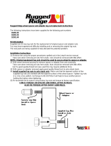
Preparing the Towing Vehicle
1. Before towing the SpeedTender, refer to towing vehicle’s operator’s manual for information concerning hitch capacities, hitch
adjustments, and tire ination.
2. Towing vehicle must be equipped with proper electric braking components.
NOTE: The SpeedTender is equipped with LED lights. The towing vehicle may require a asher upgrade for lights to operate
properly.
3. Do not exceed towing vehicle’s GVWR (Gross Vehicle Weight Rating) or GCWR (Gross Combination Weight Rating), or the maximum
hitch load.
Preparing SpeedTender
1. Hydraulics: Check routing of all hydraulic hoses. Hoses should not be kinked, twisted or rubbing against sharp edges. Check all
hoses and ttings for hydraulic leaks. Tighten, repair, or replace as required.
2. Lubrication: Lubricate SpeedTender as outlined in “General Service” on page 17. Refer to engine operator’s manual for proper
uid levels in engine.
3. Tires/Wheels: Check tire pressures and maintain at recommended operating pressure. It is important to check wheel nut/bolts for
proper torque as recommended. Refer to “Tire Service” on page 19 for proper tire pressure and wheel torque specications.
Connecting SpeedTender to the Towing Vehicle
WARNING: Do not stand between the SpeedTender and tow vehicle when hooking up.
NOTE: The SpeedTender comes standard with a 2-5/16” ball coupler and has an optional 3” lunette eye. Also, the SpeedTender
oers an optional gooseneck frame in place of the A-Frame. The gooseneck frame can feature either a 2-5/16” ball coupler or a
5th wheel hook up.
1. Back tow vehicle up to SpeedTender.
2. Align the vehicle’s ball or lunette eye with the coupler or ring on the SpeedTender.
3. Lift tongue latch lever.
4. Lower jack to set SpeedTender coupler down on ball or lunette eye hook.
5. Latch coupler and insert pin. Check to make sure that coupler is securely latched.
6. A-Frame - Pivot jack to transport position and pin in place.
Gooseneck - Raise the “drop leg” of the jack.
7. Attach 7-way plug to tow vehicle. Check the length of the SpeedTender 7-way plug to make sure it is long enough to turn, but not
too long to touch the ground.
NOTE: Check to make sure that lights are in proper operating condition and repair or replace if necessary.
8. Connect the brake breakaway cable to towing vehicle.
9. Attach safety chains to tow vehicle by crossing chains. Allow enough slack in chains to allow for turning.
10. Test the brakes and all the lights on the SpeedTender.
WARNING: Check safety chains for broken, stretched or damaged link or end ttings. Replace chains if found to be
damaged. Do not weld safety chains.
Transporting
1. Move the jack to the horizontal position before transporting.
2. Ensure the conveyor is in the conveyor rest and strapped down.
3. Ensure the collapsible hopper is in the down position with the vinyl hopper cover applied.
4. When transporting the SpeedTender on public roads, it is recommended to have the
conveyor in the forward-facing position. The rearward-facing position may not comply
with state law for lighting and marking requirements.
WARNING: Travel at a safe speed to maintain complete control of towing vehicle and SpeedTender at all times.
Operations

12
Hydraulic Power Unit Operation
Ensure all ttings and hardware are in proper operating condition. Replace if worn or broken. Check engine uid levels and sight gauge
on reservoir for proper operating levels.
1. Slide the fuel shut-o lever to the “ON” position.
2. Slide choke to the “ON” position.
3. Turn the key to the start position. Once engine starts, release key.
4. After starting, allow the engine to warm up. Slide choke to the “OFF” position and increase throttle speed.
5. The engine must throttle at, or above 80% throttle for 3 seconds to begin charge. After the 3 seconds at 80% throttle the battery will
continue to charge until the engine is turned o.
6. To turn the engine o, slide the fuel shut-o lever to the “OFF” position.
7. Turn key o.
NOTE: In extremely cold weather, it is best to allow engine and hydraulics to warm up before increasing throttle speed.
NOTE: If a hydraulic leak appears, turn o immediately and take appropriate action.
NOTE: See engine operator’s manual for more details on upkeep and service.
WARNING: Purge hydraulic system of air before operating SpeedTender to prevent serious injury or death.
WARNING: Wear proper hand and eye protection when searching for leaks. Use wood or cardboard instead of hands.
WARNING: Explosive fuel can cause res and severe burns. Stop engine before lling fuel tank.
WARNING: Carbon monoxide can cause severe nausea, fainting or death. Do not operate engine in an enclosed or conned area.
WARNING: Hot parts can cause severe burns. Do not touch engine while operating or just after stopping.
WARNING: Acid from battery can cause res and severe acid burns. Make sure to charge battery in well-ventilated area.
WARNING: Make sure to relieve hydraulic pressure before working on hydraulic system.
Operations
Key
Throttle
Fuel Shut-o
Choke

13
Field Operation
WARNING: The SpeedTender must be hooked to the towing vehicle during loading and unloading.
1. Position the SpeedTender next to the planter/drill so the conveyor will reach the planter box.
2. Release the ratchet strap from the conveyor.
3. Start the hydraulic power unit and increase throttle speed. Allow hydraulic uid to warm up.
4. Raise the conveyor o the conveyor rest using the handheld control.
WARNING: When operating the hydraulic swing option, do not stand in the operating range of the conveyor.
5. Check to make sure the hopper is in the up position.
6. Open door on SpeedTender using the supplied remote.
WARNING: Empty the rear compartment rst to prevent the chance of ipping the SpeedTender.
Ratchet Strap
Conveyor
Conveyor Rest
Operations
Operating Range
Hopper Up

14
Filling SpeedTender From Another Wagon or Bulk Container
WARNING: The SpeedTender must be hooked to the towing vehicle during loading and unloading.
1. Release ratchet strap from conveyor.
2. Start the hydraulic power unit and increase throttle speed. Allow hydraulic uid to warm up.
NOTE: Make sure collapsible hopper is in the down position.
3. Raise the conveyor o the conveyor rest using the handheld control.
CAUTION: If you are parked on an incline, the conveyor may swing freely. It is advised that you do not use SpeedTender
on uneven ground.
4. Rotate the conveyor to 45°.
5. Lower the conveyor so you can remove the telescoping spout from the discharge end of the conveyor.
6. Remove pins and raise up both handles to release ball from latch system. Slide the ball away from the middle of the tender, then
swing the collapsible hopper end out from under the SpeedTender shell.
7. Position the discharge end over the SpeedTender.
8. Lock the conveyor in place. The conveyor is equipped with a stand. (It is recommended for use whenever possible to maximize
conveyor performance and for easier access to discharge point on bulk seed containers).
Operations
Conveyor
Stand
45°
7. Use the handheld controller or wireless remote to start the conveyor.
8. Fill the planter/drill to desired level then repeat.
NOTE: Adjusting engine throttle will regulate conveyor speed.
9. Close door on SpeedTender before the last planter seed box is full so you can completely empty collapsible hopper and conveyor.
10. Position conveyor above conveyor rest and lower to allow its full weight on the conveyor rest.
11. Lock down conveyor using the ratchet strap.
12. Collapse the hopper to the down position and apply the vinyl hopper cover.
13. Slide the fuel shut-o lever to the “OFF” position. This will allow the engine to shuto by running out of gas.
14. Turn the key to the “OFF” position.

15
Operations
Conveyor Clean
Out Door
9. Lock collapsible hopper in the up position.
10. Position the wagon or bulk seed container over the collapsible hopper.
11. Use the handheld controller or wireless remote to start the conveyor.
12. Fill the SpeedTender to desired level.
WARNING: Fill the front compartment rst to help prevent the chance of ipping.
13. Run the conveyor until the collapsible hopper is empty.
14. When nished loading seed into the SpeedTender, move the wagon or bulk seed container away from conveyor.
15. Collapse the hopper to the down position and apply the vinyl hopper cover.
16. With the conveyor at a 45° angle, swing the conveyor hopper back under the tank and slide ball back into latch system. Replace both pins
on latch handles.
17. Position conveyor above the conveyor rest and lower to allow its full weight on the rest.
18. Lock down conveyor using the ratchet strap.
19. Slide the fuel shut-o lever to the “OFF” position. This will allow the engine to shuto by running out of gas.
20. Turn the key to the “OFF” position.
Cleaning out Collapsible Hopper and Conveyor
WARNING: The SpeedTender must be hooked to the towing vehicle during loading and unloading.
1. Release strap from conveyor.
2. Start the hydraulic power unit and increase throttle speed. Allow hydraulic uid to warm up if it is cold outside.
NOTE: Ensure collapsible hopper is in the down position.
3. Raise the conveyor out of conveyor rest using the handheld control.
CAUTION: If you are parked on an incline, the conveyor may swing freely. Use of the SpeedTender on uneven ground is
not advised.
4. Rotate the conveyor to 45°.
5. Lower the conveyor so you can remove the telescoping spout from the discharge end of the conveyor.
6. Swing the collapsible hopper end out from under the SpeedTender shell.
7. Place the collapsible hopper in the up position.
8. With the discharge end lower than the collapsible hopper end, place the discharge end into a 5 gallon bucket. Using the handheld
controller, start the conveyor and run until completely empty.
9. Lower the collapsible hopper end back down to the ground. This will allow you to open the conveyor clean out door.
CAUTION: Ensure all power is shut o before opening conveyor clean out door.
10. Place collapsible hopper in the down position
11. With the conveyor at a 45° angle, swing the conveyor hopper back under the tank and slide ball back into latch system. Replace both
pins on latch handles.
12. Position conveyor above conveyor rest and lower to allow its full weight on the conveyor rest.

16
Basic Scale Operations
1. Turn the scale “ON” by pressing the on/o button. The display shows “Hello” then the current weight value is displayed.
2. Press G/N to access the gross mode. (Live scale weight is displayed in the G/N weighing mode.)
3. In the gross mode, press the ZERO/CLEAR key to zero the indicator when the SpeedTender is empty.
4. After initial amount is placed on the scale, press the TARE Key. (Weight is tared o and goes into net mode, showing weight).
5. Load or unload material as needed (Shows + when loading and a – value when unloading).
6. When the display reaches the proper amount, stop loading or unloading.
7. Repeat steps 2 through 4 until complete.
NOTE: For more information, refer to the scale manual.
Basic Remote Operations
1. For instructions on pairing your remote or setting up the auto dispense feature, see the instructions decal on the inside of the scale
display box.
2. When using the optional Intercomp WC3-D remote, additional instructions can also be found in the Intercomp Operator’s Manual
provided with your SpeedTender.
Operations
Adjusting the Tarp Tension in Hanger Bracket
1. Fully unroll the tarp as shown on the right.
2. Remove the two bolts that hold the tarp u-joint on the
splined shaft.
3. Remove the u-joint from the splined shaft.
4. Rotate u-joint and handle three or four spline teeth.
5. NOTE: Rotate clockwise to tighten the tarp or
counterclockwise to loosen it.
6. Slide the u-joint and handle back onto the spline shaft.
7. Replace and tighten the two bolts.
Bolts U-Joint
Hanger
Bracket
13. Tighten strap and ensure it is secured.
14. Ensure the collapsible hopper is in the down position and apply the vinyl hopper cover.
15. Slide the fuel shut-o lever to the “OFF” position. This will allow the engine to shuto by running out of gas.
16. Turn the key to the “OFF” position.

17
Daily Service (5 -10 Hours of Use)
NOTE: J&M recommends the following service to be performed daily (every 5-10 hours of use)
1. Grease the conveyor bearings every 10 hours. Use only two pumps of grease per bearing.
NOTE: Excess lubrication of these bearings will result in premature failure.
NOTE: The conveyor has four bearing that need greased (two at each end). See “Conveyor Service” on page 21.
2. Check your belt for proper tracking every 10 hours of use and before every season. For steps to properly track your belt see ”Adjusting Conveyor
Belt Tracking” on page 23.
NOTE: When checking the belt for tracking you should empty out the conveyor clean out door. See “Cleaning out Collapsible
Hopper and Conveyor” on page 15.
3. Check hydraulic oil level.
4. Inspect for oil leaks and repair as appropriate.
5. Check all hoses, ttings, bolts, and hardware to make sure that they are secure and properly tightened.
6. Check engine oil level. See engine operator’s manual for details on oil levels, oil types and service intervals.
7. Check SpeedTender brakes and lights before towing.
8. Check the SpeedTender periodically for cracks in welds and for other structural damage. Fix cracked welds immediately.
NOTE: Failure to have cracked welds xed immediately could result in extensive damage to the SpeedTender and greatly
reduce its life.
9. Ensure tires are properly inated. Tire care guidelines can be found in “Tire Service” on page 19.
10. Ensure wheel lug nuts are properly torqued. See “Bolt Torque Specications” on page 10.
11. Ensure the conveyor hopper guard is in place. Do not remove.
12. Clean out the conveyor at the end of every day of use.
End of the Year Service
IMPORTANT: When the SpeedTender is not going to be used for a length of time, J&M recommends that you store the
SpeedTender in a dry, protected place. Leaving your SpeedTender outside and open to the weather will shorten its life.
1. Grease the conveyor bearings. Use only two pumps of grease per bearing.
NOTE: Excess lubrication of these bearings will result in premature failure.
NOTE: The conveyor has four bearing that need greased (two at each end). See “Conveyor Service” on page 21.
2. Grease pivot points on boom arm before storage.
3. The wheel bearings need to be cleaned, inspected, repacked, and adjusted. Use a number 2 wheel bearing grease to repack the bearings.
4. Inspect and service the brakes (magnets and shoes). They must be changed when they become worn or scored to prevent
inadequate vehicle braking. Clean the backing plate, magnet arm, magnet, and brake shoes. Make certain all the parts removed
are replaced in the same brake and drum assembly. Inspect the magnet arm for any loose or worn parts. Check shoe return springs,
hold down springs, and adjuster springs for stretching or deformation and replace if required.
5. If equipped with talc, be sure to empty talc box entirely and run the talc auger to completely empty talc from the auger pipe.
6. Ensure wheel lug nuts are properly torqued. See “Bolt Torque Specications” on page 10.
7. Ensure tires are properly inated. Tire care guidelines can be found in “Tire Service” on page 19.
8. Remove all seed from inside the seed tanks.
9. Clean out the conveyor at the end of every season. See “Cleaning out Collapsible Hopper and Conveyor” on page 15.
10. Tension and track the conveyor belt. See “Adjusting Conveyor Belt Tracking” on page 23.
11. Check the SpeedTender periodically for cracks in welds and for other structural damage. Have cracked welds xed immediately.
NOTE: Failure to have cracked welds xed immediately could result in extensive damage to the SpeedTender and greatly
reduce its life.
12. Check hydraulic hoses for wear and replace if needed.
13. Ensure the conveyor hopper guard is in place.
14. Remove battery from the SpeedTender and place in a cool, dry place.
NOTE: Attaching a trickle charger to the battery will help ensure a long life for your battery.
IMPORTANT: Be sure to disconnect the scales from the battery before charging.
15. Change hydraulic oil lter element with either a NAPA 1552 or a FRAM P1654A Filter.
16. Top o hydraulic oil tank with good quality hydraulic AW 32 oil.
NOTE: If the hydraulic oil appears to be “milky” in color, it should be changed immediately. Otherwise, the hydraulic oil should
be changed every 2-3 years. If the environment is extremely dusty or dirty the hydraulic oil should be changed more often.
17. Check motor oil level. See engine operator’s manual for details on oil levels, oil types, and service intervals.
18. Retract all hydraulic cylinders to prevent the piston rods from rusting.
19. Touch up spots where paint has worn away (use good quality primer paint - especially before applying graphite paint to the inside
of the shell).
General Service

18
General Service
Removing From Storage
1. Grease the conveyor bearings. Use only two pumps of grease per bearing.
NOTE: Excess lubrication of these bearings will result in premature failure.
NOTE: The conveyor has four bearings that need greased (two at each end). See “Conveyor Service” on page 21.
2. Grease pivot points on boom arm.
3. Ensure wheel lug nuts are properly torqued. See “Bolt Torque Specications” on page 10.
4. Ensure tires are properly inated. Tire care guidelines can be found in “Tire Service” on page 19.
5. Check your belt for proper tracking every 10 hours of use and before every season. For steps to properly track your belt see ”Adjusting Conveyor
Belt Tracking” on page 23.
NOTE: When checking the belt for tracking you should empty out the conveyor clean out door. See “Cleaning out Collapsible
Hopper and Conveyor” on page 15.
6. Check oil level.
7. Inspect for hydraulic oil leaks and repair as appropriate.
8. Check all hoses, ttings, bolts, and hardware to ensure they are secure and properly tightened.
9. Check engine oil level. See engine operator’s manual for details on oil levels, oil types, and service intervals.
10. Check SpeedTender brakes and lights before each time you tow.
11. Ensure the conveyor hopper guard is in place.
12. Reattach battery and check to ensure it is fully charged.
IMPORTANT: Be sure to disconnect the scales from the battery before charging.
Daily (every 5 hours of use):
1. Check oil level.
2. Inspect for oil leaks and repair as necessary.
3. Check all hoses, ttings, bolts and hardware to ensure they are secure and properly tightened.
4. Check motor oil level. See engine operator’s manual for details on oil levels, oil types, and service intervals.
Once per season (every 20-25 hours of use):
Change hydraulic oil lter element with either a NAPA 1552 or a FRAM P1654A Filter.
Every two to three years (every 75-80 hours of use):
Drain oil reservoir and rell with clean, good quality hydraulic AW 32 oil. (It is not recommended to rell with tractor hydraulic oil).
Replacing hydraulic parts:
Refer to “Hydraulics Schematic for Aluminum Valve” on page 54 or “Hydraulics Schematic for Black Intercomp Valve” on page 56 for
proper part description and part number for replacement.
Purge air from system as follows:
1. Disconnect the rod end clevis of all cylinders in a circuit and block up cylinders so the rod can completely extend and retract without
contacting any other components.
2. Pressurize the system and maintain system at full pressure for at least 5 seconds after cylinder rods stop moving. Check that all
cylinders have fully extended or retracted.
3. Check hydraulic reservoir and rell as needed.
4. Pressurize system again to reverse the motion of step 2. Maintain pressure on system for at least 5 seconds after cylinder rods stop
moving. Check that cylinders have fully extended or retracted.
5. Check for hydraulic leaks using cardboard or wood.
6. Repeat steps 2, 3, 4 and 5 (3 to 4 times).
7. Depressurize hydraulic system and connect cylinder rod clevises to their mating lugs.
Hydraulic Power Service

19
Tire Pressure
The following is to be used as a general guide for tire ination. Figures can vary depending on specic brand of tire used. It is important
that tires are inspected before and after unit is loaded. Start with the minimum pressure indicated. The tire should stand up with no
side wall buckling or distress as tire rolls. Do not exceed maximum recommended tire pressure. 235-85-R16 tires are standard on the
SpeedTender and should be inated to 80 psi. J&M also recommends rotating your tires front to back (not side to side) every 1,200
miles or 12 months (whichever comes rst) for longer tire life. The image below is a troubleshooting chart used to ensure the tires wear
evenly.
Tightening Lug Nuts
Torque 9/16”-18 lug nuts on wheels to 170 ft-lbs after the rst 10, 25, and 50 miles of driving, then recheck torque every 50 hours or every
year, whichever comes rst. Failure to do so may damage wheel nut seats. Once seats are damaged, it will become impossible to keep
nuts tight.
Tire Service

20
Clean, inspect, and repack the wheel bearings every 12 months or 12,000 miles. Use a number 2 wheel bearing grease to repack the
bearings.
Bearing Inspection and Service:
1. Jack up SpeedTender.
2. Remove wheel lug nuts.
3. Remove wheel from hub.
4. Remove grease cap.
NOTE: Be careful not to dent or cut a hole in grease cap.
5. Remove the cotter pin, nut, and washer.
6. Wiggle the hub to take the outer wheel bearing out.
7. Pull hub assembly straight o the axle. If you want to reuse the grease seal, (which is not recommended), be careful to support the
weight of the hub so that the end of the axle does not ruin the rubber part of the grease seal.
8. To remove the inner bearing, you must remove the grease seal.
9. Remove inner bearing.
10. Wash all grease and oil from the bearing cone using a suitable solvent. Dry the bearing with a clean, lint-free cloth and inspect each
roller completely. If any pitting, scalding, or corrosion is present, then the bearing must be replaced. The bearing cups inside the
hub must be inspected.
NOTE: Bearings must always be replaced in sets of a cone and a cup.
11. Repack inner bearing with new grease.
A. Place a moderate amount of grease in the palm of one hand.
B. Hold the inner bearing, large side down, in your other hand.
C. Using the edge of the bearing like an ice cream scoop, work it in until you see fresh grease come out of the top side of the
bearing.
D. Rotate 1/8 of a turn and repeat until the whole bearing is full of fresh grease.
12. Place the inner bearing in the back of the wheel hub and add a liberal dose of grease.
13. Position the new wheel seal in its recess and lightly set it with a hammer.
NOTE: Be careful to not deform the metal part of the seal.
14. Slide the hub assembly onto the spindle and push it back into position.
15. Grease the outer bearing by hand, repeating the procedure used with the inner bearing in step 11.
16. Slide the outer bearing and the spindle washer onto the spindle and into the hub recess.
17. Install and bottom out the spindle nut, then back it o 1/4 turn.
18. Reinstall the spindle nut and replace the cotter pin with a new one.
NOTE: If the castle nut does not line up with the hole in the spindle, then loosen the nut slightly until it does.
19. Pack the bearing cap with fresh grease and lightly drive it into the hub recess with a hammer.
20. Reinstall the wheel onto the hub and torque the wheel lug nuts. See “Bolt Torque Specications” on page 10.
Bearing cup replacement:
1. Place the hub on a at work surface with the cup to be replaced on the bottom side.
2. Using a brass drift punch, carefully tap around the small diameter end of the cup to drive it out.
3. After cleaning the hub bore area, replace the cup by tapping it with the brass drift punch. Be sure the cup is seated all the way up
against the retaining shoulder in the hub.
Wheel Bearing Service
/