Page is loading ...

M
Enterprise Wireless LAN Antenna
Specification Guide
Version 1.7 November 2010

© 2010 Motorola, Inc. All rights reserved.
MOTOROLA and the Stylized M Logo are registered in the US Patent & Trademark Office. Symbol is a registered
trademark of Symbol Technologies, Inc. All other product or service names are the property of their respective owners.

Contents
Chapter 1. Antenna Selection and Description
1.1 Antenna Selection. . . . . . . . . . . . . . . . . . . . . . . . . . . . . . . . . . . . . . . . . . . . . . . . . . . . . . . . . . . . . . . . . . . . . . . . . . . . . 1-1
1.2 Antenna Selection Criteria. . . . . . . . . . . . . . . . . . . . . . . . . . . . . . . . . . . . . . . . . . . . . . . . . . . . . . . . . . . . . . . . . . . . . . 1-6
1.3 Antenna Accessories for Motorola Enterprise WLANs . . . . . . . . . . . . . . . . . . . . . . . . . . . . . . . . . . . . . . . . . . . . . . . . 1-7
Chapter 2. Product Compatibility
2.1 FCC/USA Compatibility . . . . . . . . . . . . . . . . . . . . . . . . . . . . . . . . . . . . . . . . . . . . . . . . . . . . . . . . . . . . . . . . . . . . . . . . . 2-1
2.2 Antenna Suite Summary . . . . . . . . . . . . . . . . . . . . . . . . . . . . . . . . . . . . . . . . . . . . . . . . . . . . . . . . . . . . . . . . . . . . . . . . 2-3
Chapter 3. 2.4 GHz Single Band Antenna Suite
3.1 Supported 802.11b/g/n Antenna Suite. . . . . . . . . . . . . . . . . . . . . . . . . . . . . . . . . . . . . . . . . . . . . . . . . . . . . . . . . . . . . 3-1
Chapter 4. 5.2 Ghz Single Band Antenna Suite
4.1 Supported 802.11a/n Antenna Suite . . . . . . . . . . . . . . . . . . . . . . . . . . . . . . . . . . . . . . . . . . . . . . . . . . . . . . . . . . . . . . 4-1
Chapter 5. 2.4GHz - 5.2GHz Dual Band Antenna Suite
5.1 Supported 802.11a/b/g/n Dual Band Antennas . . . . . . . . . . . . . . . . . . . . . . . . . . . . . . . . . . . . . . . . . . . . . . . . . . . . . . 5-1
Chapter 6. Antenna Cables
6.1 Supported Antenna Cables . . . . . . . . . . . . . . . . . . . . . . . . . . . . . . . . . . . . . . . . . . . . . . . . . . . . . . . . . . . . . . . . . . . . . . 6-1
Chapter 7. Supported Antenna Adapters
7.1 Supported Adapters . . . . . . . . . . . . . . . . . . . . . . . . . . . . . . . . . . . . . . . . . . . . . . . . . . . . . . . . . . . . . . . . . . . . . . . . . . . 7-1
Chapter 8. Supported Lightning Arrestors
8.1 Lightning Arrestors . . . . . . . . . . . . . . . . . . . . . . . . . . . . . . . . . . . . . . . . . . . . . . . . . . . . . . . . . . . . . . . . . . . . . . . . . . . . 8-1
Chapter 9. Mounting Kits
9.1 Mounting Kit Support . . . . . . . . . . . . . . . . . . . . . . . . . . . . . . . . . . . . . . . . . . . . . . . . . . . . . . . . . . . . . . . . . . . . . . . . . . 9-1
Chapter 10. AP-5131 Antenna Connections
10.1 2.4 GHz AP-5131 Antenna Connections . . . . . . . . . . . . . . . . . . . . . . . . . . . . . . . . . . . . . . . . . . . . . . . . . . . . . . . . . . . 10-2
10.2 5 GHz AP-5131 Antenna Connections. . . . . . . . . . . . . . . . . . . . . . . . . . . . . . . . . . . . . . . . . . . . . . . . . . . . . . . . . . . . . 10-9

TOC-2 Enterprise Wireless LAN Antenna Specification Guide
Chapter 11. AP300 Antenna Connections
11.1 2.4 GHz AP300 Antenna Connections . . . . . . . . . . . . . . . . . . . . . . . . . . . . . . . . . . . . . . . . . . . . . . . . . . . . . . . . . . . . . 11-1
11.2 5 GHz AP300 Antenna Connections . . . . . . . . . . . . . . . . . . . . . . . . . . . . . . . . . . . . . . . . . . . . . . . . . . . . . . . . . . . . . . 11-8
Chapter 12. AP 7131 Transmit Power
12.1 Configuring the AP 7131 Series Transmit Power . . . . . . . . . . . . . . . . . . . . . . . . . . . . . . . . . . . . . . . . . . . . . . . . . . . . 12-1
12.2 US Regulatory Domain 2.4 GHz Band . . . . . . . . . . . . . . . . . . . . . . . . . . . . . . . . . . . . . . . . . . . . . . . . . . . . . . . . . . . . 12-8
12.3 US Regulatory Domain 5.2 GHz Band . . . . . . . . . . . . . . . . . . . . . . . . . . . . . . . . . . . . . . . . . . . . . . . . . . . . . . . . . . . 12-13
12.4 Japanese TELEC Regulatory Domain 2.4 GHz Band . . . . . . . . . . . . . . . . . . . . . . . . . . . . . . . . . . . . . . . . . . . . . . . . 12-23
12.5 Japan TELEC Regulatory Domain 5.2 GHz Band . . . . . . . . . . . . . . . . . . . . . . . . . . . . . . . . . . . . . . . . . . . . . . . . . . . 12-27
Chapter 13. AP650 Regulatory Domains
13.1 US Regulatory Domain 2.4 GHz Band. . . . . . . . . . . . . . . . . . . . . . . . . . . . . . . . . . . . . . . . . . . . . . . . . . . . . . . . . . . . . 13-1
13.2 US Regulatory Domain 5 GHz Band. . . . . . . . . . . . . . . . . . . . . . . . . . . . . . . . . . . . . . . . . . . . . . . . . . . . . . . . . . . . . . 13-7
13.3 Japan TELEC Regulatory Domain 2.4 GHz Band . . . . . . . . . . . . . . . . . . . . . . . . . . . . . . . . . . . . . . . . . . . . . . . . . . . 13-19
13.4 Japan TELEC Regulatory Domain 5 GHz Band . . . . . . . . . . . . . . . . . . . . . . . . . . . . . . . . . . . . . . . . . . . . . . . . . . . . 13-25
13.5 EU Regulatory Domain 2.4 GHz Band . . . . . . . . . . . . . . . . . . . . . . . . . . . . . . . . . . . . . . . . . . . . . . . . . . . . . . . . . . . 13-37
13.6 EU Regulatory Domain 5 GHz Band. . . . . . . . . . . . . . . . . . . . . . . . . . . . . . . . . . . . . . . . . . . . . . . . . . . . . . . . . . . . . 13-43
Chapter 14. RFS4011 Regulatory Domains
14.1 US Regulatory Domain 2.4 GHz Band . . . . . . . . . . . . . . . . . . . . . . . . . . . . . . . . . . . . . . . . . . . . . . . . . . . . . . . . . . . . . 14-1
14.2 US Regulatory Domain 5 GHz Band. . . . . . . . . . . . . . . . . . . . . . . . . . . . . . . . . . . . . . . . . . . . . . . . . . . . . . . . . . . . . . . 14-5
14.3 Canada Regulatory Domain 2.4 GHz Band . . . . . . . . . . . . . . . . . . . . . . . . . . . . . . . . . . . . . . . . . . . . . . . . . . . . . . . . 14-13
14.4 Canada Regulatory Domain 5 GHz Band . . . . . . . . . . . . . . . . . . . . . . . . . . . . . . . . . . . . . . . . . . . . . . . . . . . . . . . . . . 14-17
14.5 EU Regulatory Domain 2.4 GHz Band . . . . . . . . . . . . . . . . . . . . . . . . . . . . . . . . . . . . . . . . . . . . . . . . . . . . . . . . . . . . 14-25
14.6 EU Regulatory Domain 5 GHz Band. . . . . . . . . . . . . . . . . . . . . . . . . . . . . . . . . . . . . . . . . . . . . . . . . . . . . . . . . . . . . . 14-29
Chapter 15. AP-6511 Regulatory Domains
15.1 US Regulatory Domain 2.4 GHz Band . . . . . . . . . . . . . . . . . . . . . . . . . . . . . . . . . . . . . . . . . . . . . . . . . . . . . . . . . . . . . 15-1
15.2 US Regulatory Domain 5 GHz Band. . . . . . . . . . . . . . . . . . . . . . . . . . . . . . . . . . . . . . . . . . . . . . . . . . . . . . . . . . . . . . . 15-2
15.3 EU Regulatory Domain 2.4 GHz Band . . . . . . . . . . . . . . . . . . . . . . . . . . . . . . . . . . . . . . . . . . . . . . . . . . . . . . . . . . . . . 15-3
15.4 EU Regulatory Domain 5 GHz Band. . . . . . . . . . . . . . . . . . . . . . . . . . . . . . . . . . . . . . . . . . . . . . . . . . . . . . . . . . . . . . 15-4
Appendix A.Technical Support

About This Guide
Introduction
This guide provides an RF engineer a catalog of antenna parts and accessories to complete a customized RF
environment. This guide specifically addresses the antennas used for 2.4 GHz, 5.2 GHz and dual band
antenna implementations for Wireless Local Area Networks (WLANs).
It is important to understand that antenna and accessory selection should be qualified by on-site testing with
the actual components used. Signal attenuation is cumulative with each connection and component added
between the antenna and the radio, so careful study should verify the given arrangement delivers the
expected results.
Document Conventions
The following conventions are used in this document to draw your attention to important information:
NOTE: Illustrations displayed in this guide are samples and can differ from the actual
antenna.
NOTE: Indicate tips or special requirements.
CAUTION: Indicates conditions that can cause equipment damage or data loss.
WARNING! Indicates a condition or procedure that could result in
personal injury or equipment damage.
!

viii Enterprise Wireless LAN Antenna Specification Guide
Notational Conventions
The following additional notational conventions are used in this document:
• Italics are used to highlight the following:
• Chapters and sections in this and related documents
• Dialog box, window and screen names
• Drop-down list and list box names
• Check box and radio button names
• Icons on a screen.
• GUI text is used to highlight the following:
• Screen names
• Menu items
• Button names on a screen.
• bullets (•) indicate:
• Action items
• Lists of alternatives
• Lists of required steps that are not necessarily sequential
• Sequential lists (those that describe step-by-step procedures) appear as numbered lists.

Antenna Selection and Description
1.1 Antenna Selection
While several antennas may work in a given environment, some will provide better coverage than others.
Using the right antenna in the right location will maximize both the performance and coverage of your
network. Understanding the key characteristics that describe how an antenna sends and receives radio
frequency signals is critical to finding the ideal antenna for your deployment. This guide supports the
antennas used for AP-5131, AP-5181, AP-7131 and AP-6511 model access points, AP650 and AP300 (non-
integrated antenna) model access port and the RFS4011 Integrated Services Controller.
Motorola Enterprise Wireless LAN products operate in the 2.4 GHz and 5 GHz ISM bands allocated for
unlicensed use. Access point and access port products available today support either the 802.11b/g/n or the
802.11a/n standard, or both. Wireless devices conforming to the 802.11b/g standard operate in the 2.4 GHz
ISM band, while 802.11a devices operate in the 5 GHz band. The antennas in this guide are grouped
according to the frequency band they support. Some antennas are designed to operate within either band.
These antennas (described as "Dual-band") may be connected to radios operating in either the 2.4 or 5 GHz
bands, although a single antenna may not be connected to two radios at the same time.

1-2 Enterprise Wireless LAN Antenna Specification Guide
1.1.1 Connector Types and Definitions
There are combinations of antenna types and cables required to provide a satisfactory connection to the AP.
One confusing factor is “reverse polarity”. Reverse polarity is the FCC's requirement for each WLAN
manufacturer to have unique access point connectors. Motorola (Symbol) had previously standardized our
offerings for access points/ports:
• 2.4 GHz is Reverse polarity BNC female (RP-BNC-F)
• 5 GHz is reverse polarity SMA female (RP-SMA-F)
• Dual Band is reverse polarity SMA female (for AP-5131), and N-Female (for AP-5181).
The following are the connectors used within this guide:
Figure 1.1 RP-BNC-F
Figure 1.2 RP-BNC-M
NOTE: Reverse polarity presents confusion because of a lack of a standardized definition
from connector manufactures. Reverse polarity provides a center element, which should
not be confused with a male connector. A male connector is defined by the outer jacket of
the connector rather than the center element.

Antenna Selection and Description 1-3
Figure 1.3 RP-SMA-F
Figure 1.4 RP-SMA-M

1-4 Enterprise Wireless LAN Antenna Specification Guide
Additionally, antennas deployed outdoors and industry standard accessories (like lightening arrestors) use
Type-N connectors (as displayed below). Therefore, with the combinations devices required
(access points/ports, antennas, cable extensions, and lightening arrestors), various adapter cables are
required to connect an antenna to an access point/port.
Figure 1.5 Type N-F
Figure 1.6 Type N-M

Antenna Selection and Description 1-5
1.1.2 Indoor and Outdoor Antennas
One important aspect of an antenna is whether it is weather sealed to protect it from the environment
Because of this extra protection, outdoor antennas are typically more expensive than those rated for indoor
use. Outdoor antennas can be used for indoor applications, such as freezers and cooler where moisture is
common. Outdoor antennas can be used for indoor applications, but indoor applications should not be used
in outdoor applications.
One common distinction of outdoor antennas is the connector. Since lightning protection is always advised
for outdoor antennas, these antennas typically have Type N Male to directly attach the lightning arrestor.
This is true of 2.4 GHz, 5 GHz, and dual-band outdoor antennas.
1.1.3 Spectrum and Part Number Designations
The antennas listed in this document are ultimately referenced by part number. A numerical sequence is used
within each antenna’s part number to identify the spectrum supported by the antennas.
• The antenna part numbers with a 2499 indicates a 2.4 GHz antenna. For more information on the 2.4 GHz
antenna suite, see 2.4 GHz Single Band Antenna Suite on page 3-1.
• The antenna part numbers with a 5299 indicates a 5 GHz antenna. For more information on the 2.4 GHz
antenna suite, see 5.2 Ghz Single Band Antenna Suite on page 4-1.
• The antenna part numbers with a 2452 indicates a dual band antenna (2.4GHz and 5 GHz). For more
information on the 2.4 GHz antenna suite, see 2.4GHz - 5.2GHz Dual Band Antenna Suite on page 5-1.
1.1.4 Extended AP to Antenna Cable Lengths
Most indoor antennas are intended to be mounted directly to the AP's connectors. Some mounting
arrangements call for positioning the AP a significant distance away from the antenna due to serviceability
or other reason. In these situations, various adapters and cable extensions are required.
In these situations be mindful of:
• The connector on the AP
• The connector on the antenna
• The spectrum being implemented
• Signal loss due to multiple connectors and long cable lengths
Combinations of these attributes present different parts required to complete the connection. The Product
Compatibility matrix addresses the parts required to make a proper connection. For more information, see
FCC/USA Compatibility on page 2-1.

1-6 Enterprise Wireless LAN Antenna Specification Guide
1.2 Antenna Selection Criteria
In addition to antenna frequency, there is other criteria to consider when selecting an antenna.
1.2.1 Antenna Pattern
1.2.1.1 Omni-Directional
Signal radiates from the antenna in all directions on the horizontal plane.
1.2.1.2 Directional
Signal radiates in a specific direction, typically described as a beam of given width, expressed in degrees in
the horizontal and vertical plane. For more information, see Azimuth 3dB Beamwidth on page 1-7 and
Elevation 3dB Beamwidth on page 1-7.
1.2.2 Antenna Type
1.2.2.1 Panel
A panel antenna is a flat antenna mounted to a wall or other vertical surface and radiates RF energy (radio
waves) directionally away from the wall. They usually have gain greater than 5 dBi and are not suitable for
omni-directional situations. Ideally suited for long hallways.
1.2.2.2 Patch
A patch antenna is a flat antenna mounted on the ceiling but whose pattern is omni-directional. Most of the
energy goes out horizontally to the sides of the antenna and equal in all directions.
1.2.2.3 Dipole
A dipole antenna is a tubular antenna that can be either a pipe shape, a straight flexible rod or a paddle. This
antenna has an omni-directional pattern when placed in a vertical position. It usually has 2 dBi of gain.
1.2.2.4 Dipole Array
Essentially a dipole, a dipole array is two or more dipoles that are placed one on top of the other, requiring
a longer tube to hold them. The advantage of a dipole array is that it has higher gain.
1.2.2.5 Parabolic Grid
A parabolic grid antenna is a very directional, dish-like antenna. Its parabolic reflector focuses the RF energy
like a flashlight. Most of the time the radiating element is a dipole, but when combined with the dish, it
becomes very directional with gain up to 24 dBi. Usually used in long point-to-point systems.
1.2.2.6 Yagi
A yagi antenna is a antenna that has an internal structure resembling that of typical antennas used for TV
reception (a series of rods perpendicular to a main rod, making a triangular shape). This is a directional
antenna with less gain than the PGA, typically around 13 dBi. It may be used in either point-to-point
situations, or to cover a very long, narrow area in point-to-multi-point situations.

Antenna Selection and Description 1-7
1.2.3 Antenna Performance Characteristics
1.2.3.1 Frequency
The frequency band within which the antenna performs at the stated specifications
1.2.3.2 Gain (dBi)
The relative amplification of the antenna with respect to an equivalent isotropic antenna, expressed on the
decibel logarithmic scale.
1.2.3.3 Cable loss (dB)
The signal strength loss introduced by the cable connected to the antenna expressed on the decibel
logarithmic scale.
1.2.3.4 Net gain (dBi)
The resulting amplification of the antenna paired with its cable.
1.2.3.5 Polarization
The orientation of the electrical field which the antenna is optimized to receive. If the transmitting and
receiving antennas are both linear polarized, then turning one 90° so that they are cross polarized will reduce
the range significantly.
1.2.3.6 VSWR
Voltage Standing Wave Ratio (VSWR) is the ratio of maximum voltage to minimum voltage along the line.
Expresses the degree of match between the transmission line and the terminating element (antenna). When
VSWR is 1:1 the match is perfect, a VSWR of 1.5:1 corresponds to 96% power efficiency.
1.2.3.7 Azimuth 3dB Beamwidth
Width of the antenna beam on the horizontal plane expressed in degrees.
1.2.3.8 Elevation 3dB Beamwidth
Height of the antenna beam on the vertical plane expressed in degrees.
1.3 Antenna Accessories for Motorola Enterprise WLANs
Motorola offers a complete selection of antennas and accessories to ensure optimal coverage and
performance for wireless LANs. Regardless of the size or layout of your environment, from a small office or
storefront to campus-wide, multiple-site, indoor and outdoor deployments, Motorola offers the antennas,
cables and accessories designed to fit your needs.
By combining this portfolio with a broad line of wireless switches, access ports, access points, client
connectivity cards, ruggedized mobile voice/data devices and network management software, as well as
wireless mobility planning and deployment services, Motorola offers comprehensive end-to-end wireless
enterprise LAN solutions, giving you secure, reliable access to your critical business data and applications
at the point of activity. For more information on Motorola's wireless products, visit www.motorola.com.

1-8 Enterprise Wireless LAN Antenna Specification Guide
1.3.1 Choosing the Right Antenna and accessories for your WLAN
It is important to consider a number of factors when choosing an antenna and accessories for your Motorola
enterprise WLAN. To choose the right components, you'll need to know:
• Where is the antenna to be installed, and what type of coverage is required. Knowing the intended radio
band is central. Determine if the intended radio coverage area supports dual 2.4/5.2 band traffic. Has the
antenuation of the coverage been discerned in respect to known barriers.
• The band (802.11b/g/n or 802.11a/n) your network supports
• Which Motorola AP to use
• Whether you will be deploying the network indoors or outdoors
• The distance between AP and antenna, to determine extender cable length, if any
• The serviceablity requirement for each AP and antenna deployment
Review the chart to determine which antennas suit your needs. Using the part numbers provided, determine
which of the antennas will work with your hardware in your environment.

Product Compatibility
To find the right antenna and accessories for your deployment:
• Find your Motorola access point or access port model at the top of the chart (refer to the chart on the
following page). Follow that column down to find the antennas, cables and lightning arrestors
compatible with that model access port or access point. Write those part numbers down.
• Follow the row antenna across the table to the columns for the lightning arrestors and cables you wrote
down to confirm that they compatible with the antenna you've chosen and determine if an adaptor is
required to connect the two selected parts.
2.1 FCC/USA Compatibility
The following displays Motorola’s FCC approved AP radio, antenna, cable and accessory combinations for
use in the United States:

2-2 Enterprise Wireless LAN Antenna Specification Guide
AP300 (H9PWSAP5100)
AP300 B/G (H9PWSAP5100bg)
AP-5131 (H9PA5131)
AP-5181 (H9PA5181)
AP-7131 ABGN (UZ7AP7131)
AP-7131N ABGN (UZ7AP7131N)
AP-650 (UZ7MB82)
ML-1499-100JK-01R
ML-1499-10JK-01R
ML-1499-25JK-01R
ML-1499-50JK-01R
ML-1499-72PJ-01R
ML-1499-LAK1-01R
ML-1499-LAK2-01R
ML-2452-LAK1-01R
ML-2499-11PNA2-01R * *3X333 1111* 222
ML-2499-5PNL-72-N 88XX77X
A
A
A
A
X ***
ML-2499-7PNA2-01R * *3X33X 1111* 222
ML-2499-APA2-01 * *XX333 XXXXX XXX
ML-2499-BPNA3-01R 99XX55X ****X X*X
ML-2499-BYGA2-01R 996X55X ****X X*X
ML-2499-FHPA5-01R 889*777
A
A
A
A
X
ML-2499-FHPA9-01R 88X*777
A
A
A
A
X
ML-2499-HPA3-01R * *3X333 1111* 222
ML-2499-PNAHD-01R * *3X33X 1111* 222
ML-2499-SD3-01R * *XX333 1111* 222
ML-5299-APA1-01R *X * X * * * XXXXX XXX
ML-5299-BYGA15-012 XXXXX * X ****X
ML-5299-FHPA10-01R XXX * XX *
A
A
A
A
X
ML-5299-FHPA6-01R XXX****
A
A
A
A
X
ML-5299-HPA1-01R *X*X* * * 4444X 555
ML-5299-PTA1-01R *XXX* * * 4444X 555
ML-5299-WPNA1-01R *X*X* *X 4444X 555
ML-2452-APA2-01 * * *X * * * XXXXX XXX
ML-2452-PNA5-01R * *X*777
A
A
A
A
X
ML-2452-PNA7-01R XXX * 7 7X
A
A
A
A
X
ML-2452-PTA2M3X3-1 XXXX * * X
ML-2452-PTA3M3-036 XXXX * * *
ML-2452-HPA5-036 XXXX * * *
ML-2452-PNL9M3-036 XXXX * * X
ML-2452-APA6J-01 XXXX * * *
ML-1499-LAK1-01R X*X XXX ****X
ML-1499-LAK2-01R XXX XXX ****X
ML-2452-LAK1-01R *X* *XX ****X
ML-1499-100JK-01R 7X7*777
ML-1499-10JK-01R 7X7*777
ML-1499-25JK-01R 7X7*777
ML-1499-50JK-01R 7X7*777
ML-1499-72PJ-01R * *XXXXX
1 ML-1499-RBNCA1-01R
2 ML-1499-RBNCA2-01R
3 25-72178-01
4 25-90262-01R
5 25-90263-01R
6 25-85391-01R
7 25-85392-01R
8 must use ML-1499-LAK1-01R
9 25-97261-01R
A
25-99175-01R
* Compatible
X Not compatible
Not required
Cables LAs 2.4 GHz5 GHz
LAsCablesAP Radios
Antennas
Dual

Product Compatibility 2-3
2.2 Antenna Suite Summary
The following aligns Motorola’s antenna suite with their respective part numbers, description, band, gain,
mounting orientation, radiation patterns, outdoor versus indoor deployment and plenum rating.
Part Number Description Cable
Peak
Gain(dBi)
(Note1) Mount Az BW
Outdoor
rated
Plenum
(Cable
only)
ML-5299-APA1-01R ANT:5.5 GHz, DP AJ,CBL 0,SMARP-F none 2 S 360 No No
ML-5299-PTA1-01R ANT:5.5 GHz, PTCH,CBL 36",SMARP-F 36 in 4.6 H 360 No Yes
ML-5299-HPA1-01R ANT:5.5 GHz, DPA,CBL 36",RPSMA-F 36 in 5 V 360 Yes Yes
ML-5299-FHPA6-01R ANT:4.9-5.9 GHz, FIXED DP, TYPE N-M none 6 V 360 Yes No
ML-5299-FHPA10-01R ANT:5.8 GHz, FIXED DP, TYPE N-M none 8 V 360 Yes No
ML-5299-WPNA1-01R ANT:5.5 GHz, PNL,CBL 36",RPSMA-F 36 in 12.5 V 31 Yes TBD
ML-5299-BYGA15-012 ANT: Yagi 4.9-5.5GHz 36 in 13.9 V 31 Yes No
ML-2499-APA2-01 ANT:OMNI,2400-2500MHz none 2 S 60 No No
ML-2499-HPA3-01R ANT:S24,DP,CBL 48",BNCRP-F 48 in 3.3 V 360 Yes TBD
ML-2499-SD3-01R ANT:S24,PTCH,CBL 48",BNCRP-F 48 in 3.5 H 360 No Yes
ML-2499-PNAHD-01R ANT:S24,PNL,CBL 48",BNCRP-F 48 in 6.3 V 55 No TBD
ML-2499-7PNA2-01R ANT:2.4GHz,INDOOR,65 DEGREE PNL 48 in 6.3 V 60 No Yes
ML-2499-5PNL-72-N ANT:2.4GHz,PNL,LP,CBL 72",TYPE N 72 in 5.5 V 135 Yes Yes
ML-2499-11PNA2-01R ANT:S24,SECTR PNL,CBL 96",BNCRP-F 96 in 8.5 V 97 No Yes
ML-2499-FHPA5-01R ANT:2.4GHz,FIXED DP,TYPE N-M none 5 V 360 Yes No
ML-2499-FHPA9-01R ANT:2.4GHz,FIXED DP,TYPE N-M none 6 V 360 Yes No
ML-2499-BPNA3-01R ANT:S24,PNL,CBL 12",TYP N-F 12 in 13.9 V 31 Yes TBD
ML-2499-BYGA2-01R ANT:S24,YAGI,CBL 12",TYP N-F 12 in 14.1 V 34 Yes TBD
ML-2499-BPDA1-01R ANT:S24,DISH,TYP N-F none 23.5 V 10 Yes TBD
ML-2452-PTA2M3X3-1 ANT:11ABG,AP7131,MIMO3X3,1IN,RPSMA n/a 3 / 5 S 360 No No
ML-2452-APA2-01 ANT:2.4-5.2GHz DUALBAND,DP,SMARP-F none 6 / 7 S 360 No No
ML-2452-PTA3M3-036 ANT:11ABG,MIMO3,PTCH,36IN,RPSMA 36 in 3 / 7 H 360 No Yes
ML-2452-PNA5-36R ANT:DUAL BAND PANEL,RP-SMA(M) 36 in 4 / 6 V 60 TBD Yes
ML-2452-PNA5-01R ANT:2.4/5 GHz,SECTOR 120,TYPE N-M 12 in 4.5 / 5 V 120 Yes Yes
ML-2452-PNA7-01R ANT:2.4/5 GHz,SECTOR 60,TYPE N-M 12 in 7 / 9 V 60 Yes Yes
ML-2452-HPA5-036 ANT:11ABG,DP,CBL 36",RPSMA-M 36 in 2.9 /4.9 V 360 Yes No
ML-2452-PNL9M3-036 ANT: MIMO DUAL BAND SECTOR 36 in 11 / 14 V 75 Yes Yes
ML-2452-APA6J-01 ANT:DUAL BAND, DP AJ, RP-SMA none -6 / -8 S 360 No No
H - ceiling mount (Patches)
V - Wall or mast mount (Panels, Yagi, Dishes)
S - Switchable (elbow jointed)
Note 1: Peak Gain does not include cable loss.
Outdoor
Omnidirectionals
Directionals
Patch
Plenum

2-4 Enterprise Wireless LAN Antenna Specification Guide

2.4 GHz Single Band Antenna Suite
3.1 Supported 802.11b/g/n Antenna Suite
Motorola supports numerous single-band 2.4 GHz 802.11b/g/n antennas to suit the requirements of your unique
access point or access port deployment. Check the Motorola Web site periodically, as newly supported 802.11b/g/n
antennas will be added to this document as they are released. For more information, go to
h
ttp://support.symbol.com/support/product/manuals.do.
For detailed information on supported 802.11b/g/n antenna models, refer to:
• ML-2499-5PNL-72-N Outdoor 135° Panel Antenna: Male Connector
• ML-2499-7PNA2-01R Indoor 60° Diversity Panel: RP-BNC Male
• ML-2499-11PNA2-01R Outdoor 97°Sector Panel: RP-BNC Male
• ML-2499-APA2-01R Indoor Rubber Flex, Elbow Joint Dipole: RP-BNC Male
• ML-2499-BPDA1-01R Outdoor 10°High-Gain Dish: 20.5 N Female
• ML-2499-BPNA3-01R Outdoor 35° High-Gain Directional Panel: Type N - Female
• ML-2499-BYGA2-01R Outdoor 35° High-Gain Directional Yagi: N Female
• ML-2499-HPA3-01R High Performance Omni-Directional "Pipe" Antenna: RP-BNC Male
• ML-2499-PNAHD-01R Indoor 55°Directional Panel: RP-BNC Male
• ML-2499-SD3-01R Low Profile Ceiling/Surface Mount Omni-Directional Patch: RP-BNC Male
• ML-2499-FHPA5-01R Omni-Directional "Pipe" Antenna: N Male Connector
• ML-2499-FHPA9-01R High Performance Fixed Point Dipole: Male Connector
NOTE: For examples on how various antenna and connectors are deployed in a 2.4 GHz
AP-5131 installation, see 2.4 GHz AP-5131 Antenna Connections.

3-2 Enterprise Wireless LAN Antenna Specification Guide
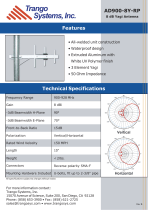
3.1.1 ML-2499-5PNL-72-N Outdoor 135° Panel Antenna: Male Connector
Type Panel
Frequency 2400-2500 MHz
Gain (dBi) 5.5
Polarization Linear, Vertical
Azimuth 3dB Beamwidth: 135°
Elevation 3dB Beamwidth: 56°
Cable Length (in.) 72
Cable Type RG-58 Ultralink
Connector Type Type N Male
Weight 0.5 lb
Plenum Antenna No
Plenum Cable Yes
Outdoor Rated Yes
/