Agilent Technologies 6023A User manual
- Category
- Power supply units
- Type
- User manual
This manual is also suitable for

SERVICE MANUAL
AUTORANGING
DC POWER SUPPLY
AGILENT MODELS
6023A and 6028A
Agilent Part No. 5964-8283
FOR INSTRUMENTS WITH SERIAL NUMBERS
Agilent Model 6023A; Serials US36490101 and above
Agilent Model 6028A; Serials US36520101 and above
For instruments with higher serial numbers, a change page may be included.
Microfiche Part No. 5964-8284 Printed in USA: July 2001

2
CERTIFICATION
Agilent Technologies certifies that this product met its published specifications at time of shipment from the factory. Agilent
Technologies further certifies that its calibration measurements are traceable to the United States National Institute of
Standards and Technology, to the extent allowed by the Institute’s calibration facility, and to the calibration facilities of
other International Standards Organization members.
WARRANTY
This Agilent Technologies hardware product is warranted against defects in material and workmanship for a period of three
years from date of delivery. Agilent Technologies software and firmware products, which are designated by Agilent
Technologies for use with a hardware product and when properly installed on that hardware product, are warranted not to
fail to execute their programming instructions due to defects in material and workmanship for a period of 90 days from date
of delivery. During the warranty period Agilent Technologies will, at its option, either repair or replace products which
prove to be defective. Agilent Technologies does not warrant that the operation of the software, firmware, or hardware shall
be uninterrupted or error free.
For warranty service, with the exception of warranty options, this product must be returned to a service facility designated
by Agilent. Technologies. Customer shall prepay shipping charges by (and shall pay all duty and taxes) for products
returned to Agilent Technologies. for warranty service. Except for products returned to Customer from another country,
Agilent Technologies shall pay for return of products to Customer.
Warranty services outside the country of initial purchase are included in Agilent Technologies’ product price, only if
Customer pays Agilent Technologies international prices (defined as destination local currency price, or U.S. or Geneva
Export price).
If Agilent Technologies is unable, within a reasonable time to repair or replace any product to condition as warranted, the
Customer shall be entitled to a refund of the purchase price upon return of the product to Agilent Technologies.
LIMITATION OF WARRANTY
The foregoing warranty shall not apply to defects resulting from improper or inadequate maintenance by the Customer,
Customer-supplied software or interfacing, unauthorized modification or misuse, operation outside of the environmental
specifications for the product, or improper site preparation and maintenance. NO OTHER WARRANTY IS EXPRESSED
OR IMPLIED. AGILENT TECHNOLOGIES SPECIFICALLY DISCLAIMS THE IMPLIED WARRANTIES OF
MERCHANTABILITY AND FITNESS FOR A PARTICULAR PURPOSE.
EXCLUSIVE REMEDIES
THE REMEDIES PROVIDED HEREIN ARE THE CUSTOMER’S SOLE AND EXCLUSIVE REMEDIES. AGILENT
TECHNOLOGIES SHALL NOT BE LIABLE FOR ANY DIRECT, INDIRECT, SPECIAL, INCIDENTAL, OR
CONSEQUENTIAL DAMAGES, WHETHER BASED ON CONTRACT, TORT, OR ANY OTHER LEGAL THEORY.
ASSISTANCE
The above statements apply only to the standard product warranty. Warranty options, extended support contracts, product
maintenance agreements and customer assistance agreements are also available. Contact your nearest Agilent
Technologies Sales and Service office for further information on Agilent Technologies’ full line of Support Programs.

3
SAFETY SUMMARY
The following general safety precautions must be observed during all phases of operation, service and repair of this
instrument. Failure to comply with these precautions or with specific warnings elsewhere in this manual violates safety
standards of design, manufacture, and intended use of the instrument. Agilent Technologies, Inc. assumes no liability for the
customer's failure to comply with these requirements.
BEFORE APPLYING POWER.
Verify that the product is set to match the available line voltage and the correct fuse is installed.
GROUND THE INSTRUMENT.
This product is a Safety Class 1 instrument (provided with a protective earth terminal). To minimize shock hazard, the instrument chassis
and cabinet must be connected to an electrical ground. The instrument must be connected to the ac power supply mains through a three-
conductor power cable, with the third wire firmly connected to an electrical ground (safety ground) at the power outlet. For instruments
designed to be hard wired to the ac power lines (supply mains), connect the protective earth terminal to a protective conductor before any
other connection is made. Any interruption of the protective (grounding) conductor or disconnection of the protective earth terminal will
cause a potential shock hazard that could result in personal injury. If the instrument is to be energized via an external autotransformer for
voltage reduction, be certain that the autotransformer common terminal is connected to the neutral (earth pole) of the ac power lines
(supply mains).
INPUT POWER MUST BE SWITCH CONNECTED.
For instruments without a built-in line switch, the input power lines must contain a switch or another adequate means for disconnecting
the instrument from the ac power lines (supply mains).
DO NOT OPERATE IN AN EXPLOSIVE ATMOSPHERE.
Do not operate the instrument in the presence of flammable gases or fumes.
KEEP AWAY FROM LIVE CIRCUITS.
Operating personnel must not remove instrument covers. Component replacement and internal adjustments must be made by qualified
service personnel. Do not replace components with power cable connected. Under certain conditions, dangerous voltages may exist even
with the power cable removed. To avoid injuries, always disconnect power, discharge circuits and remove external voltage sources before
touching components.
DO NOT SERVICE OR ADJUST ALONE.
Do not attempt internal service or adjustment unless another person, capable of rendering first aid and resuscitation, is present.
DO NOT EXCEED INPUT RATINGS.
This instrument may be equipped with a line filter to reduce electromagnetic interference and must be connected to a properly grounded
receptacle to minimize electric shock hazard. Operation at the line voltage or frequencies in excess of those stated on the data plate may
cause leakage currents in excess of 5.0mA peak.
SAFETY SYMBOLS.
Instruction manual symbol: the product will be marked with this symbol when it is necessary for the user to refer to the
instruction manual (refer to Table of Contents) .
Indicates hazardous voltages.
Indicate earth (ground) terminal.
The WARNING sign denotes a hazard. It calls attention to a procedure, practice, or the like, which, if not correctly
performed or adhered to, could result in personal injury. Do not proceed beyond a WARNING sign until the indicated
conditions are fully understood and met.
The CAUTION sign denotes a hazard. It calls attention to an operating procedure, or the like, which, if not correctly
performed or adhered to, could result in damage to or destruction of part or all of the product. Do not proceed beyond
a CAUTION sign until the indicated conditions are fully understood and met.
DO NOT SUBSTITUTE PARTS OR MODIFY INSTRUMENT.
Because of the danger of introducing additional hazards, do not install substitute parts or perform any unauthorized modification to the
instrument. Return the instrument to a Agilent Technologies, Inc. Sales and Service Office for service and repair to ensure that safety
features are maintained.
Instruments which appear damaged or defective should be made inoperative and secured against unintended operation until they can be
repaired by qualified service personnel.

4
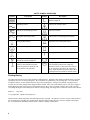
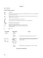
SAFETY SYMBOL DEFINITIONS
Symbol Description Symbol Description
Direct current Terminal for Line conductor on permanently
installed equipment
Alternating current Caution, risk of electric shock
Both direct and alternating current Caution, hot surface
Three-phase alternating current Caution (refer to accompanying documents)
Earth (ground) terminal In position of a bi-stable push control
Protective earth (ground) terminal Out position of a bi-stable push control
Frame or chassis terminal On (supply)
Terminal for Neutral conductor on
permanently installed equipment
Off (supply)
Terminal is at earth potential
(Used for measurement and control
circuits designed to be operated with
one terminal at earth potential.)
Standby (supply)
Units with this symbol are not completely
disconnected from ac mains when this switch is
off. To completely disconnect the unit from ac
mains, either disconnect the power cord or have
a qualified electrician install an external switch.
Printing History
The edition and current revision of this manual are indicated below. Reprints of this manual containing minor corrections
and updates may have the same printing date. Revised editions are identified by a new printing date. A revised edition
incorporates all new or corrected material since the previous printing date. Changes to the manual occurring between
revisions are covered by change sheets shipped with the manual. Also, if the serial number prefix of your power supply is
higher than those listed on the title page of this manual, then it may or may not include a change sheet. That is because
even though the higher serial number prefix indicates a design change, the change may not affect the content of the manual.
Edition 1 July, 2001
© Copyright 2001 Agilent Technologies, Inc.
This document contains proprietary information protected by copyright. All rights are reserved. No part of this document
may be photocopied, reproduced, or translated into another language without the prior consent of Agilent Technologies,
Inc. The information contained in this document is subject to change without notice.

5
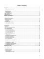
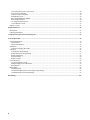
TABLE OF CONTENTS
Introduction ............................................................................................................................................................................7
Scope ....................................................................................................................................................................................7
Calibration and Verification .............................................................................................................................................7
Troubleshooting................................................................................................................................................................7
Principles of Operation ..................................................................................................................................................... 7
Replaceable Parts..............................................................................................................................................................7
Circuit Diagrams...............................................................................................................................................................7
Safety Considerations ...........................................................................................................................................................7
Manual Revisions .................................................................................................................................................................8
Calibration and Verification..................................................................................................................................................9
Introduction...........................................................................................................................................................................9
Test Equipment Required .....................................................................................................................................................9
Operation Verification Tests.................................................................................................................................................9
Calibration Procedure ...........................................................................................................................................................9
Initial Setup..................................................................................................................................................................... 11
Performance Tests ..............................................................................................................................................................14
Measurement Techniques ...............................................................................................................................................14
Constant Voltage (CV) Tests..........................................................................................................................................15
Constant Current (CC) Tests...........................................................................................................................................21
Troubleshooting ....................................................................................................................................................................23
Introduction.........................................................................................................................................................................23
Initial Troubleshooting Procedures.....................................................................................................................................23
Electrostatic Protection.......................................................................................................................................................25
Repair and Replacement .....................................................................................................................................................25
A2 Control Board Removal ............................................................................................................................................ 26
A4 Power Mesh Board Removal ....................................................................................................................................27
A3 Front-Panel Board Removal...................................................................................................................................... 27
A1 Main Board Removal................................................................................................................................................ 27
Overall Troubleshooting Procedure.................................................................................................................................... 27
Using the Tables ............................................................................................................................................................. 28
Main Troubleshooting Setup ..........................................................................................................................................29
Troubleshooting No-Output Failures..............................................................................................................................31
Front-Panel Troubleshooting .......................................................................................................................................... 31
Troubleshooting Bias Supplies .......................................................................................................................................33
Power Section Blocks ..................................................................................................................................................... 35
Troubleshooting AC-Turn-on Circuits............................................................................................................................35
Troubleshooting PWM & Clock..................................................................................................................................... 36
Troubleshooting DC-To-DC Converter..........................................................................................................................37
Troubleshooting CV Circuit ...........................................................................................................................................38
Troubleshooting CC Circuit............................................................................................................................................38
Troubleshooting Down Programmer ..............................................................................................................................39
Troubleshooting OVP Circuit.........................................................................................................................................39
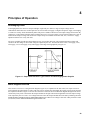
Principles of Operation ........................................................................................................................................................43
Autoranging Power.............................................................................................................................................................43
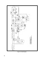
Block Diagram Overview ...................................................................................................................................................43
Simplified Schematic...................................................................................................................................................... 45
DC-to-DC Converter....................................................................................................................................................... 47
Down Programmer.......................................................................................................................................................... 47
Constant-Voltage (CV) Circuit .......................................................................................................................................48
Constant-Current (CC) Circuit........................................................................................................................................49

6
Overvoltage Protection (OVP) Circuit............................................................................................................................ 49
Power-Limit Comparator................................................................................................................................................ 49
Control-Voltage Comparator ..........................................................................................................................................49
Initial-Ramp Circuit........................................................................................................................................................50
Pulse-Width Modulator (PWM) .....................................................................................................................................50
Bias Voltage Detector.....................................................................................................................................................50
AC-Surge Dropout Detector ........................................................................................................................................... 50
1-Second-Delay Circuit ..................................................................................................................................................51
Display Circuits .................................................................................................................................................................. 51
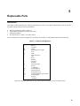
Replaceable Parts..................................................................................................................................................................53
Introduction.........................................................................................................................................................................53
Ordering Information.......................................................................................................................................................... 54
Component Location and Circuit Diagrams ...................................................................................................................... 69
System Option 002 ................................................................................................................................................................ 79
General Information............................................................................................................................................................79
Specifications..................................................................................................................................................................79
Option 002 Hardware...................................................................................................................................................... 79
Installation ..........................................................................................................................................................................83
Connector Assembly Procedure......................................................................................................................................83
Operation ............................................................................................................................................................................84
Local/Remote Programming...........................................................................................................................................85
Remote Resistance Programming...................................................................................................................................87
Remote Monitoring......................................................................................................................................................... 89
Status Indicators..............................................................................................................................................................90
Remote Control...............................................................................................................................................................90
Power-On Preset .................................................................................................................................................................92
AC Dropout Buffer Circuit .............................................................................................................................................93
Multiple Supply System Shutdown ................................................................................................................................93
Bias Supplies ..................................................................................................................................................................94
Maintenance........................................................................................................................................................................ 94
Troubleshooting..............................................................................................................................................................95
Troubleshooting Resistance and Voltage Programming.................................................................................................95
Troubleshooting Current Programming..........................................................................................................................95
Backdating........................................................................................................................................................................... 107

7
1
Introduction
Scope
This manual contains information for troubleshooting the Agilent 6023A or 6028A 200W Autoranging Power Supply to the
component level. Wherever applicable, the service instructions given in this manual refer to pertinent information provided
in the Operation Manual. Both manuals cover Agilent Models 6023A/28A; differences between models are described as
required.
The following information is contained in this manual.
Calibration and Verification
Contains calibration procedures for Agilent Models 6023A/28A. Also contains verification procedures that check the
operation of the supplies to ensure they meet the specifications of Chapter 1 in the Operating Manual.
Troubleshooting
Contains troubleshooting procedures to isolate a malfunction to a defective component on the main circuit board or to a
defective assembly (front-panel, power transformer, or cable assembly). Board and assembly level removal and
replacement procedures are also given in this section.
Principles of Operation
Provides block diagram level descriptions of the supply's circuits. The regulation & control, protection, input power, dc
power conversion and output circuits are described. These descriptions are intended as an aid in troubleshooting.
Replaceable Parts
Provides a listing of replaceable parts for all electronic components and mechanical assemblies for Agilent Models
6023A/28A.
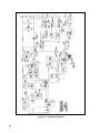
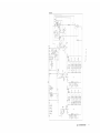
Circuit Diagrams
Contains functional schematics and component location diagrams for all Agilent 6023A/28A circuits. The names that
appear on the functional schematics also appear on the block diagrams in Chapter 4. Thus, the descriptions in Chapter 4 can
be correlated with both the block diagrams and the schematics.
Safety Considerations
This product is a Safety Class 1 instrument, which means that it is provided with a protective earth terminal. Refer to the
Safety Summary page at the beginning of this manual for a summary of general safety information. Safety information for
specific procedures is located at appropriate places in the manual.

8
Manual Revisions
Agilent Technologies instruments are identified by a 10-digit serial number. The format is described as follows: first two
letters indicate the country of manufacture. The next four digits are a code that identify either the date of manufacture or of
a significant design change. The last four digits are a sequential number assigned to each instrument.
Item Description
US The first two letters indicates the country of manufacture, where US = USA; MY = Malaysia.
3648 This is a code that identifies either the date of manufacture or the date of a significant design change.
0101 The last four digits are a unique number assigned to each power supply.
If the serial number prefix on your unit differs from that shown on the title page of this manual, a yellow Manual Change
sheet may be supplied with the manual. It defines the differences between your unit and the unit described in this manual.
The yellow change sheet may also contain information for correcting errors in the manual.
Note that because not all changes to the product require changes to the manual, there may be no update information
required for your version of the supply.
Older serial number formats used with these instruments had a two-part serial number, i.e. 2701A-00101. This manual also
applies to instruments with these older serial number formats. Refer to Appendix B for backdating information.

9
2
Calibration and Verification
Introduction
This section provides test and calibration procedures. The operation-verification tests comprise a short procedure to verify
that the unit is performing properly, without testing all specified parameters. After troubleshooting and repair of a defective
power supply you can usually verify proper operation with the turn-on checkout procedure in the Operating Manual.
Repairs to the A1 main board and the A2 control board can involve circuits which, although functional, may prevent the
unit from performing within specified limits. So, after A1 or A2 board repair, decide if recalibration and operation
verification tests are needed according to the faults you discover. Use the calibration procedure both to check repairs and
for regular maintenance.
When verifying the performance of this instrument as described in this chapter, check only those specifications for which a
performance test procedure is included.
Test Equipment Required
Table 2-1 lists the equipment required to perform the tests of this section. You can separately identify the equipment for
performance tests, calibration and troubleshooting using the USE column of the table.
Operation Verification Tests
To assure that the unit is performing properly, without testing all specified parameters, first perform the turn-on checkout
procedure in the Operating Manual. Then perform the following performance tests, in this section.
CV Load Effect
CC Load Effect
Calibration Procedure
Calibrate the unit twice per year and when required during repair. The following calibration procedures which follow
should be performed in the sequence given. Table 2-2 describes in detail these calibration procedures and lists the expected
results to which each adjustment must be made.
Note: Some of the calibration procedures for this instrument can be performed independently, and some
procedures must be performed together and/or in a prescribed order. If a procedure contains no references
to other procedures, you may assume that it can be performed independently.
To return a serviced unit to specifications as quickly as possible with minimal calibration, the technician
need only perform calibration procedures that affect the repaired circuit. Table 2-3 lists various power
supply circuits with calibration procedures that should be performed after those circuits are serviced.

10
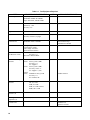
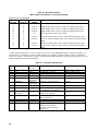
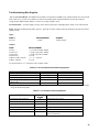
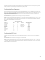
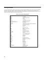
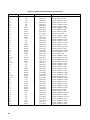
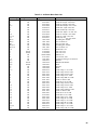
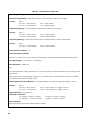
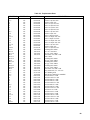
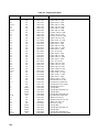
Table 2-1. Test Equipment Required
TYPE REQUIRED CHARACTERISTICS USE RECOMMENDED MODEL
Oscilloscope Sensitivity: 1 mV
Bandwidth: 20MHz & 100MHz
Input: differential, 50Ω & 10MΩ
P,T Agilent 1740A
RMS Voltmeter True rms, 10MHz bandwidth
Sensitivity: 1 mV
Accuracy: 5%
P Agilent 3400B
Logic Pulser 4.5 to 5.5Vdc @ 35mA T Agilent 546A
Multimeter Resolution: 100nV
Accuracy: 0.0035%, 6½ digit
P,A,T Agilent 3458A
CC PARD Test
Current Probe
No saturation at 30Adc
Bandwidth: 20Hz to 20MHz
P Tektronix P6303
Probe/AM503 Amp/
TM500 Power Module
Electronic Load* Voltage range: 60Vdc
Current range: 60Adc
Power range: 300 watts
Open and short switches
P,A Agilent 6060B
CC PARD Test & I
P
Cal Resistive Load*
Value: 0.25 ohms >250W
Accuracy: 1%
Rheostat or Resistor Bank
P,A
Current-Monitoring
Resistors
6023A
Value: 30mV @ 30A (1mΩ )
Accuracy: 1%
TC: 30ppm/°C
Value: 30mV @ 30A (1mΩ)
Accuracy: 0.05% **
TC: 30ppm/°C (A,P)
6028A
Value 100MΩ ± 0.04% @ 25W
Accuracy: 1%
PC: 0.0004% 1W
P,A
Guidline 9230/15
Calibration and Test
Resistors
Value: 100Ω, 5%, 1W
1Ω, 5%, 1/2W
1KΩ, 5% 1/4W
5KΩ, 5% 1/4W (6023A)
2KΩ, 0.01% 1/4W
A,T
Terminating
Resistors (4)
Value: 50Ω ±5%, noninductive
P
Blocking
Capacitors (2)
Value: 0.01µF, 100Vdc
P
Common-mode
Toroidal Core
P Ferrox-Cube
500T600-3C8,
Agilent 9170-0061

11
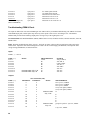
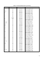
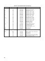
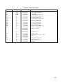
Table 2-1. Test Equipment Required (continued)
TYPE REQUIRED CHARACTERISTICS USE RECOMMENDED MODEL
Switch SPST, 30A @ 20V P
DC Power Supply Voltage range: 0-60Vdc
Current range: 0-3Adc
T,P Agilent 6296A
Variable Voltage
Transformer
(autotransformer)
Range greater than -13% to +6% of
nominal input AC voltage
1KVA
P,A
P = performance testing A = calibration adjustments T = troubleshooting
* Resistors may be substituted for test where an electronic load is not available.
** Less accurate, and less expensive, current-monitor resistors can be used, but the accuracy to which current programming
and current meter reading can be checked must be reduced accordingly.
Initial Setup
Maintenance described herein is performed with power supplied to the instrument, and protective covers
removed. Such maintenance should be performed only by service trained
personnel who are aware of the hazards involved (for example, fire and electrical shock).
Turn off ac power when making or removing connections to the power supply. Where
maintenance can be performed without power applied, the power should be
removed.
a. Unplug the line cable and remove the top cover by removing three screws; the rear handle screw and the two top-rear
corner screws. Do not remove the front handle screw as the retaining nut will fall into the unit.
b. Slide the cover to the rear.
c. Plug a control board test connector A2P3 onto the A2J3 card-edge fingers.
d. Turn OVERVOLTAGE ADJUST control A3R59 fully clockwise.
e. Disconnect all loads from output terminals.
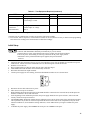
f. Connect power supply for local sensing, and ensure that MODE switches are set as shown below.
g. Reconnect the line cable and turn on ac power.
h. Allow unit to warm up for 30 minutes.
i. When attaching the DVM, the minus lead of the DVM should be connected to the first node listed, and the plus lead
should be connected to the second node listed.
j. At the beginning of each calibration procedure, the power supply should be in its power-off state, with no external
circuitry connected except as instructed.
k. The POWER LIMIT adjustment (A2R25) must be adjusted at least coarsely before many of the calibration procedures
can be performed. If you have no reason to suspect that the Power Limit circuit is out of adjustment, and you do not
intend to recalibrate it, do not disturb its setting. Otherwise, center A2R25 before you begin to calibrate the power
supply.
l. To disable the power supply, short INHIBIT line A2J3 pin 8 to COMMON A2J3 pin 4.

12
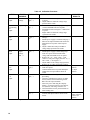
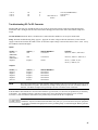
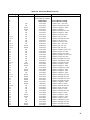
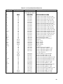
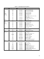
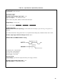
Table 2-2. Calibration Procedure
TEST TESTED
VARIABLE
TEST POINTS TEST SEQUENCE AND ADJUSTMENTS EXPECTED
RESULTS
Meter F/S
Adjust.
Meter Ref.
Voltage
A2J3 pin 6 ( + )
M ( - )
a. Connect DVM across test points and turn on
ac power.
b. Adjust A2R24 to obtain the voltage range
specified in the results.
0.5V ± 50µV
Resistance
Programming
F/S
Adjust.
Prog. Voltage VP ( + )
P ( - )
a. Connect a 2KΩ 0.01%, ¼W programming
resistor and DVM between test points.
b. Set MODE switch as in Figure 2-1 and turn on
ac power.
c. Adjust A2R23 to obtain the voltage range
specified in the results.
2.5V ±4mV
V-MON
Zero
Adjust.
V-MON VM ( + )
M ( - )
a. Set voltage and current controls to minimum
settings.
b. Disable power supply as in Initial Setup step i.
c. Short circuit output terminals and connect the
DVM between test points. Turn on power
supply.
d. Adjust V-MON Zero trim pot A2R22 to
voltage range specified in the results.
0 ± 20µV
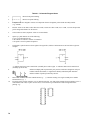
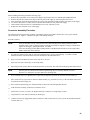
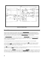
Common
Mode
Adjust.
Residual
Output
Voltage
VM( + )
VM ( + )
M ( - )
a. Set voltage and current controls to minimum.
b. Disable power supply as Initial Setup step i.
c. Turn on ac power and record the initial
voltage (IR) with DVM across test points.
d. Remove the - S( + ) and – OUT( - ) and
connect a 1Vdc power supply between - S( + )
and – OUT( - ). See Figure 2-1.
e. Adjust A2R21 to the voltage range specified.
f. Remove the 1V supply and replace jumpers.
IR ± 20µV
I-MON
Zero
Adjust.
I-MON IM ( + )
M (-)
a. Set voltage and current controls to minimum.
b. Turn on ac power.
c. Connect DVM across test points and adjust
I-MON Zero trim pot A2R8 as shown in
results.
0 ± 100µV
(6023A)
0 ± 25µV
(6028A)
I-MON
F / S
Adjust.
I-MON IM ( + )
M ( - )
a. Perform I-MON Zero Adjust before
proceeding .
b. Connect a 0.001Ω 0.05% (6023A), 0.100Ω
0.05% (6028A) current monitoring resistor
Rm across the output terminals.
c. Turn on ac power and using the “Display
Setting”, set current control to 30A (6023A),
10A (6028A), and voltage control to 5V.
d. Connect DVM across test points and take an
initial reading (IR).
IR*
Rm ( + )
Rm ( - )
e. Connect DVM across Rm monitoring
terminals and adjust A2R9 as shown in the
results.
0.006 IR*
+40µV (6023A),
0.200 ± 1µV
(6028A)
*IR = Initial Reading

13
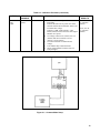
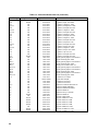
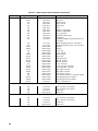
Table 2-2. Calibration Procedure (continued)
TEST TESTED
VARIABLE
TEST POINTS TEST SEQUENCE AND ADJUSTMENTS EXPECTED
RESULTS
Power
Limit
Adjust.
V(OUT)
I(OUT)
a. Perform I-MON F/S Adjust before
proceeding.
b. Connect the unit to the ac power line via the
external variable auto-transformer which is set
to nominal line voltage.
c. Connect a 0.25Ω, 250W (6023A), 2.3Ω,
250W (6028A) resistor across the unit's output
and turn on ac power.
d. Set voltage control to 9V (6023A) 9V≥ 3V
(6028A) and current control to 30.2A
(6023A), 10.2A (6028A)
e. Set auto-transformer to minimum line
voltage.
f. Turn A2R25 fully counterclockwise.
g. Slowly adjust A2R25 clockwise until CC
LED just lights.
30.2A 7.55V for
CC operation
(6023A)
10.2A, 23V for
CC operation
(6028A)
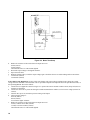
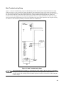
Figure 2-1. Common Mode Setup

14
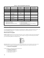
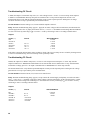
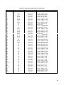
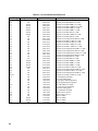
Table 2-3. Guide to Recalibration After Repair
Printed Circuit
Board
Block Name Circuit Within
Block
Ref.
Designator
Perform These
Procedures*
A1 Main Board R3 4
A1 Main Board T1 4 then 5
A4 Power Mesh T3 4 then 5 Board
A4 Power Mesh CR7 4 then 5 Board
A2 Control Board Constant Voltage
(CV) Circuit
All Except Current
Source
All 1 then 2
A2 Control Board Constant Voltage
(CV) Circuit
Current Source All 6
A2 Control Board Constant Current
(CC) Circuit
All 3 then 4
A2 Control Board Power Limit
Comparator
All 4 then 5
A2 Control Board Bias Power Supplies
± 15V Supplies
All All
A2 Control Board U9, R79, R80, R24 7
* Code To Calibration Procedure To Be Performed
1. V-MON Zero Calibration
2. Common-Mode Calibration
3. I-MON Full Scale (F/S) Zero Calibration
4. I-MON Full Scale (F/S) Calibration
5. Power Limit Calibration
6. Resistance Programming Full Scale (F/S) Calibration
7. Meter Full Scale (F/S) Calibration
Performance Tests
The following paragraphs provide test procedures for verifying the unit's compliance with the specifications of Table 1-1 in
the Operating Manual. Please refer to CALIBRATION PROCEDURE or TROUBLESHOOTING if you observe
out-of-specification performance.
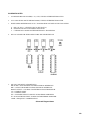
Measurement Techniques
Setup For All Tests. Measure the output voltage directly at the + S and - S terminals. Connect unit for local sensing, and
ensure that MODE switches are set as shown below. Select an adequate wire gauge for load leads using the procedures
given in the Operating Manual for connecting the load.
Electronic Load. The test and calibration procedures use an electronic load to test the unit quickly and accurately. If an
electronic load is not available, you may substitute a 2Ω 250W load resistor for the electronic load in these tests:
CV Source Effect (Line Regulation)
CC Load Effect (Load Regulation)
You may substitute a 0.25Ω 250W load resistor in these tests:
CV Load Effect (Load Regulation)
CV PARD (Ripple and Noise)
CC Source Effect (Line Regulation)
CC PARD (Ripple and Noise)

15
The substitution of the load resistor requires adding a load switch to open and short the load in the CC or CV load
regulation tests. The load transient recovery time test procedure cannot be performed using load resistors.
An electronic load is considerably easier to use than a load resistor. It eliminates the need for connecting resistors or
rheostats in parallel to handle the power, it is much more stable than a carbon-pile load, and it makes easy work of
switching between load conditions as is required for the load regulation and load transient-response tests.
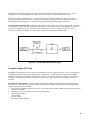
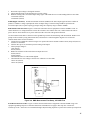
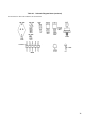
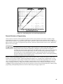
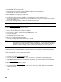
Current-Monitoring Resistor Rm. To eliminate output current measurement error caused by voltage drops in the leads
and connections, connect the current-monitoring resistor between -OUT and the load as a four-terminal device. Figure 2-2
shows correct connections. Select a resistor with stable characteristics: 0.001, 1% accuracy, 30 ppm/°C or lower
temperature coefficient and 20W power rating (20 times actual power if other than 0.001Ω is used).
Figure 2-2. Current-Monitoring Resistor Setup
Constant Voltage (CV) Tests
CV Setup. If more than one meter or a meter and an oscilloscope are used, connect each to the + S and - S terminals by a
separate pair of leads to avoid mutual coupling effects. Connect only to + S and -S (except for peak-to-peak PARD)
because the unit regulates the output voltage between + S and - S, not between + OUT and - OUT. Use coaxial cable or
shielded 2-wire cable to avoid pickup on test leads. For all CV tests set the output current at full output to assure CV
operation.
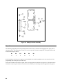
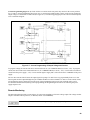
Load Effect (Load Regulation). Constant-voltage load effect is the change in dc output voltage (Eo) resulting from a
load-resistance change from open-circuit to full-load. Full-load is the resistance which draws the maximum rated output
current at voltage Eo. Proceed as follows:
a. Connect the test equipment as shown in Figure 2-3. Operate the load in constant resistance mode (Amps/Volt) and set
resistance to maximum.
b. Turn the unit's power on, and turn up current setting to full output.
c. Turn up output voltage to:
7.0Vdc (6023A)
20.0Vdc (6028A)
as read on the digital voltmeter.

16
Figure 2-3. Basic Test Setup
d. Reduce the resistance of the load to draw an output current of:
29Adc (6023A)
10Adc (6028A)
Check that the unit's CV LED remains lighted.
e. Record the output voltage at the digital voltmeter.
f. Open-circuit the load.
g. When the reading settles, record the output voltage again. Check that the two recorded readings differ no more than:
± 0.0027Vdc (6023A)
± 0.0090Vdc (6028A)
Source Effect (Line Regulation). Source effect is the change in dc output voltage resulting from a change in ac input
voltage from the minimum to the maximum value as specified in Input Power Requirements in the Specifications Table, in
the Operating Manual. Proceed as follows:
a. Connect the test equipment as shown in Figure 2-3. Operate the load in constant resistance mode (Amps/Volt) and set
resistance to maximum.
b. Connect the unit to the ac power line through a variable autotransformer which is set for low line voltage (104Vac for
120Vac).
c. Turn the unit's power on, and turn up current setting to full output.
d. Turn up output voltage to:
20.0Vdc (6023A)
60Vdc (6028A)
as read on the digital voltmeter.
e. Reduce the resistance of the load to draw an output current of:
10Adc (0.010Vdc across Rm) (6023A)
3.3Adc(0.33Vdc across Rm) (6028A)
Check that the unit's CV LED remains lighted.

17
f. Record the output voltage at the digital voltmeter.
g. Adjust autotransformer to the maximum for your line voltage.
h. When the reading settles record the output voltage again. Check that the two recorded readings differ no more than:
± 0.0030Vdc (6023A)
± 0.0080Vdc (6028A)
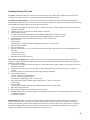
PARD (Ripple And Noise). Periodic and random deviations (PARD) in the unit's output-ripple and noise-combine to
produce a residual ac voltage superimposed on the dc output voltage. Constant-voltage PARD is specified as the
root-mean-square (rms) or peak-to-peak (pp) output voltage in a frequency range of 20Hz to 20MHz.
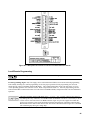
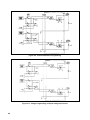
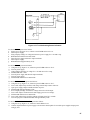
RMS Measurement Procedure. Figure 2-4 shows the interconnections of equipment to measure PARD in Vrms. To
ensure that there is no voltage difference between the voltmeter's case and the unit's case, connect both to the same ac
power outlet or check that the two ac power outlets used have the same earth-ground connection.
Use the common-mode choke as shown to reduce ground-loop currents from interfering with measurement. Reduce noise
pickup on the test leads by using 50Ω coaxial cable, and wind it five turns through the magnetic core to form the
common-mode choke. Proceed as follows:
a. Connect the test equipment as shown in Figure 2-4. Operate the load in constant resistance mode (Amps/Volt) and set
resistance to maximum.
b. Turn the unit's power on, and turn up current setting to full output.
c. Turn up output voltage to:
7Vdc (6023A)
20Vdc (6028A)
d. Reduce the resistance of the load to draw an output current of:
29Adc (6023A)
10Adc (6028A)
Check that the unit's CV LED remains lighted.
e. Check that the rms noise voltage at the true rms voltmeter is no more than:
3.0mV rms (6023A)
3.0mV rms (6028A)
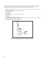
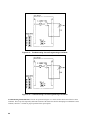
Figure 2-4. RMS Measurement Test Setup, CV PARD Test
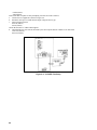
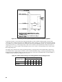
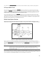
Peak Measurement Procedure. Figure 2-5 shows the interconnections of equipment to measure PARD in Vpp. The
equipment grounding and power connection instructions of PARD rms test apply to this setup also. Connect the
oscilloscope to the + OUT and - OUT terminals through 0.01µF blocking capacitors to protect the oscilloscope's input from

18
the unit's output voltage. To reduce common-mode noise pickup, set up the oscilloscope for a differential, two-channel
voltage measurement. To reduce normal-mode noise pickup, use twisted, 1 meter or shorter, 50Ω coaxial cables with
shields connected to the oscilloscope case and to each other at the other ends. Proceed as follows:
a. Connect the test equipment as shown in Figure 2-5. Operate the load in constant resistance mode (Amps/Volt) and set
resistance to maximum.
b. Turn the unit's power on, and turn up current setting to full output.
c. Turn up output voltage to:
7.0Vdc (6023A)
20Vdc (6028A)
d. Reduce the resistance of the load to draw an output current of:
29.0Adc (6023A)
10Adc (6028A)
Check that the unit's CV LED remains lighted.
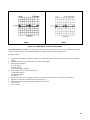
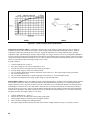
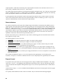
e. Set the oscilloscope's input impedance to 50Ω and bandwidth to 20MHz. Adjust the controls to show the 20KHz and
higher frequency output-noise waveform of Figure 2-6.
f. Check that the peak-to-peak is no more than 30mV.
Figure 2-5. Peak-To-Peak Measurement Test Setup, CV PARD Test

19
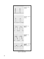
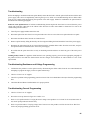
6023A 6028A
Figure 2-6. 20KHz Noise, CV Peak-to-Peak PARD
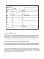
Load Transient Recovery Time. Specified for CV operation only; load transient recovery time is the time for the output
voltage to return to within a specified band around its set voltage following a step change in load.
Proceed as follows:
a. Connect the test equipment as shown in Figure 2-3. Operate the load in constant-current mode and set for minimum
current.
b. Turn the unit's power on, and turn up current setting to full output.
c. Turn up output voltage to:
6.70Vdc (6023A)
20.0Vdc (6028A)
as read on the digital voltmeter.
d. Set the load to vary the load current between:
27 and 30Adc (6023A)
9 and 10Adc (6028A)
at a 30Hz rate.
e. Set the oscilloscope for ac coupling, internal sync and lock on either the positive or negative load transient.
f. Adjust the oscilloscope to display transients as in Figure 2-7.
g. Check that the pulse width of the transient pulse is no more than:
50mV (6023A)
75mV (6028A)

20
6023A 6028A
Figure 2-7. Load Transient Recovery Waveform
Temperature Coefficient. (6023A) Temperature coefficient (TC) is the change in output voltage for each °C change in
ambient temperature with constant ac line voltage, constant output voltage setting and constant load resistance. Measure
temperature coefficient by placing the unit in an oven, varying the temperature over a range within the unit's operating
temperature range, and measuring the change in output voltage. Use a large, forced air oven for even temperature distribution.
Leave the unit at each temperature measurement for half hour to ensure stability in the measured variable. Measure the output
voltage with a stable DVM located outside the oven so voltmeter drift does not affect the measurement accuracy. To measure
offset TC, repeat the procedure with output voltage set to 0.10Vdc.
Proceed as follows:
a. Connect DVM between +S and -S.
b. Place power supply in oven, and set temperature to 30°C.
c. Turn the unit's power on and turn up current setting to full output.
d. Turn up output voltage to 20Vdc as read on the DVM.
e. After 30 minutes stabilization record the temperature to the nearest 0.1°C. Record the output voltage at the DVM.
f. Set oven temperature to 50°C.
g. After 30 minutes stabilization, record the temperature to the nearest 0.1°C. Record output voltage.
h. Check that the magnitude of the output voltage change is no greater than 32mV.
Drift (Stability) (6023A). Drift is the change in output voltage beginning after a 30-minute warm-up during 8 hours operation
with constant ac input line voltage, constant load resistance and constant ambient temperature. Use a DVM and record the
output at intervals, or use a strip-chart recorder to provide a continuous record. Check that the DVM's or recorder's specified
drift during the 8 hours will be no more than 0.001%. Place the unit in a location with constant air temperature preferably a
large forced-air oven set to 30°C and verify that the ambient temperature does not change by monitoring with a thermometer
near the unit. Typically the drift during 30 minute warm-up exceeds the drift during the 8-hour test. To measure offset drift,
repeat the procedure with output voltage set to 0.10Vdc.
a. Connect DVM between + S and - S.
b. Turn the unit's power on and turn up current setting to full output.
c. Turn up output voltage to 20Vdc as read on the digital voltmeter.
d. After a 30 minute warmup, note reading on DVM.
e. The output voltage should not deviate more than 5mV from the reading obtained in step d over a period of 8 hours.
Page is loading ...
Page is loading ...
Page is loading ...
Page is loading ...
Page is loading ...
Page is loading ...
Page is loading ...
Page is loading ...
Page is loading ...
Page is loading ...
Page is loading ...
Page is loading ...
Page is loading ...
Page is loading ...
Page is loading ...
Page is loading ...
Page is loading ...
Page is loading ...
Page is loading ...
Page is loading ...
Page is loading ...
Page is loading ...
Page is loading ...
Page is loading ...
Page is loading ...
Page is loading ...
Page is loading ...
Page is loading ...
Page is loading ...
Page is loading ...
Page is loading ...
Page is loading ...
Page is loading ...
Page is loading ...
Page is loading ...
Page is loading ...
Page is loading ...
Page is loading ...
Page is loading ...
Page is loading ...
Page is loading ...
Page is loading ...
Page is loading ...
Page is loading ...
Page is loading ...
Page is loading ...
Page is loading ...
Page is loading ...
Page is loading ...
Page is loading ...
Page is loading ...
Page is loading ...
Page is loading ...
Page is loading ...
Page is loading ...
Page is loading ...
Page is loading ...
Page is loading ...
Page is loading ...
Page is loading ...
Page is loading ...
Page is loading ...
Page is loading ...
Page is loading ...
Page is loading ...
Page is loading ...
Page is loading ...
Page is loading ...
Page is loading ...
Page is loading ...
Page is loading ...
Page is loading ...
Page is loading ...
Page is loading ...
Page is loading ...
Page is loading ...
Page is loading ...
Page is loading ...
Page is loading ...
Page is loading ...
Page is loading ...
Page is loading ...
Page is loading ...
Page is loading ...
Page is loading ...
Page is loading ...
Page is loading ...
Page is loading ...
-
 1
1
-
 2
2
-
 3
3
-
 4
4
-
 5
5
-
 6
6
-
 7
7
-
 8
8
-
 9
9
-
 10
10
-
 11
11
-
 12
12
-
 13
13
-
 14
14
-
 15
15
-
 16
16
-
 17
17
-
 18
18
-
 19
19
-
 20
20
-
 21
21
-
 22
22
-
 23
23
-
 24
24
-
 25
25
-
 26
26
-
 27
27
-
 28
28
-
 29
29
-
 30
30
-
 31
31
-
 32
32
-
 33
33
-
 34
34
-
 35
35
-
 36
36
-
 37
37
-
 38
38
-
 39
39
-
 40
40
-
 41
41
-
 42
42
-
 43
43
-
 44
44
-
 45
45
-
 46
46
-
 47
47
-
 48
48
-
 49
49
-
 50
50
-
 51
51
-
 52
52
-
 53
53
-
 54
54
-
 55
55
-
 56
56
-
 57
57
-
 58
58
-
 59
59
-
 60
60
-
 61
61
-
 62
62
-
 63
63
-
 64
64
-
 65
65
-
 66
66
-
 67
67
-
 68
68
-
 69
69
-
 70
70
-
 71
71
-
 72
72
-
 73
73
-
 74
74
-
 75
75
-
 76
76
-
 77
77
-
 78
78
-
 79
79
-
 80
80
-
 81
81
-
 82
82
-
 83
83
-
 84
84
-
 85
85
-
 86
86
-
 87
87
-
 88
88
-
 89
89
-
 90
90
-
 91
91
-
 92
92
-
 93
93
-
 94
94
-
 95
95
-
 96
96
-
 97
97
-
 98
98
-
 99
99
-
 100
100
-
 101
101
-
 102
102
-
 103
103
-
 104
104
-
 105
105
-
 106
106
-
 107
107
-
 108
108


Agilent Technologies 6023A User manual
- Category
- Power supply units
- Type
- User manual
- This manual is also suitable for
Ask a question and I''ll find the answer in the document
Finding information in a document is now easier with AI
Related papers
-
Agilent Technologies 90B User manual
-
-
Agilent Technologies 11899A User manual
-
Agilent Technologies 6023A, 6028A User manual
-
-
-
-
-
-
Agilent Technologies 6610XA User manual
