
(English)
DM-GN0001-24
Dealer's Manual
General Operations

2
CONTENTS
IMPORTANT NOTICE ........................................................................................................... 7
TO ENSURE SAFETY ............................................................................................................ 8
REAR DERAILLEUR 9
TO ENSURE SAFETY .......................................................................................................... 10
REAR DERAILLEUR FOR MTB/TREKKING ......................................................................... 12
Installation of the rear derailleur ...................................................................................................................... 12
Stroke adjustment .............................................................................................................................................. 14
Securing the cable .............................................................................................................................................. 16
SIS adjustment .................................................................................................................................................... 21
Replacing the pulley ........................................................................................................................................... 23
REAR DERAILLEUR FOR ROAD ......................................................................................... 25
Installation of the rear derailleur ...................................................................................................................... 25
Stroke adjustment .............................................................................................................................................. 27
Securing the cable .............................................................................................................................................. 30
SIS adjustment .................................................................................................................................................... 32
Replacing the pulley ........................................................................................................................................... 34
FRONT DERAILLEUR 35
TO ENSURE SAFETY .......................................................................................................... 36
FRONT DERAILLEUR FOR MTB/TREKKING ....................................................................... 37
Installation .......................................................................................................................................................... 37
Fixing the cable and adjusting the SIS (Front double) ..................................................................................... 43
Fixing the cable and adjusting the SIS (Front triple) ........................................................................................ 49
FRONT DERAILLEUR FOR ROAD ....................................................................................... 53
Installation .......................................................................................................................................................... 53
Fixing the cable and adjusting the SIS (Front double) ..................................................................................... 55
Fixing the cable and adjusting the SIS (Front triple) ........................................................................................ 60
MAINTENANCE ................................................................................................................. 66

3
CHAIN 67
TO ENSURE SAFETY .......................................................................................................... 68
CHAIN CONNECTING PIN .................................................................................................. 71
Method of use .................................................................................................................................................... 71
QUICK-LINK ....................................................................................................................... 72
Installing a QUICK-LINK (SM-UG51) .................................................................................................................. 73
Installing a QUICK-LINK (SM-CN900-11) ............................................................................................................ 75
Removing a QUICK-LINK (SM-CN900-11) .......................................................................................................... 76
BRAKE 77
TO ENSURE SAFETY .......................................................................................................... 78
DISC BRAKE ....................................................................................................................... 82
Wheel spoke lacing ............................................................................................................................................ 82
Installation of the disc brake rotor ................................................................................................................... 82
INSTALLATION (HYDRAULIC DISC BRAKES) .................................................................... 87
Installation of the brake lever ........................................................................................................................... 87
Installation of the brake hose ........................................................................................................................... 89
Installation of the brake hose (easy hose joint system) ................................................................................... 93
Replacing the brake hose (easy hose joint system) ........................................................................................ 103
Preventing loosening of frame fixing bolts .................................................................................................... 107
MAINTENANCE (HYDRAULIC DISC BRAKES) ................................................................. 110
Brake pad replacement .................................................................................................................................... 110
Adjustment when the pistons are not operating correctly ........................................................................... 113
Lever stroke adjustment .................................................................................................................................. 114
Free stroke adjustment .................................................................................................................................... 114
Installation of the magnet holder ................................................................................................................... 115
Mineral oil replacement ................................................................................................................................... 115
Adding mineral oil and bleeding air ............................................................................................................... 116
INSTALLATION (V-BRAKE BRAKES) ................................................................................ 121
Installation of the brake lever ......................................................................................................................... 121
Installing the power modulator ...................................................................................................................... 121
Installation of V-BRAKE brakes ........................................................................................................................122

4
MAINTENANCE (V-BRAKE BRAKES) ............................................................................... 125
Replacement of the cartridge shoe ................................................................................................................. 125
BRAKE LEVER WITH SWITCH INTERCHANGEABILITY
(V-BRAKE AND HUB ROLLER BRAKES) .......................................................................... 126
For V-BRAKE (with power modulator) mode .................................................................................................126
For Caliper brake/Roller brake ......................................................................................................................... 126
INSTALLATION (DUAL PIVOT CALIPER BRAKES) ........................................................... 127
Arch spring tension adjustment ...................................................................................................................... 130
MAINTENANCE (DUAL PIVOT CALIPER BRAKES) .......................................................... 131
Replacement of the cartridge shoe ................................................................................................................. 131
SPECIFICATIONS (CANTILEVER BRAKES) ....................................................................... 132
Cantilever brakes .............................................................................................................................................. 132
Brake lever ........................................................................................................................................................ 132
INSTALLATION (CANTILEVER BRAKES) .......................................................................... 133
Installation of the brake lever ......................................................................................................................... 133
Installation of the brake caliper ...................................................................................................................... 134
Installing SM-CB70 ............................................................................................................................................ 137
FRONT CHAINWHEEL 138
TO ENSURE SAFETY ........................................................................................................ 139
INSTALLATION (CHAINRINGS) ........................................................................................ 141
For ROAD .......................................................................................................................................................... 141
For MTB/Trekking ............................................................................................................................................. 142
INSTALLATION (FRONT CHAINWHEEL) .......................................................................... 143
HOLLOWTECH II / 2 piece crankset .................................................................................................................. 143
OCTALINK TYPE ................................................................................................................................................ 148
SQUARE TYPE ................................................................................................................................................... 149
INSTALLATION (PRESS-FIT BOTTOM BRACKET) ............................................................ 151
Adapter ............................................................................................................................................................. 151
Assembly example ............................................................................................................................................ 151
Installation ........................................................................................................................................................ 152
Removal ............................................................................................................................................................ 153

5
PEDALS (SPD-SL PEDALS/SPD PEDALS) 154
TO ENSURE SAFETY ........................................................................................................ 155
INSTALLATION (SPD PEDALS) ......................................................................................... 157
Engaging the cleats with the pedals ............................................................................................................... 157
Releasing the cleats from the pedals .............................................................................................................. 157
Attaching the cleats ......................................................................................................................................... 159
Mounting the pedals on the crank arms ........................................................................................................ 161
Adjusting the spring tension of the binding .................................................................................................. 162
Cleat replacement ............................................................................................................................................ 162
INSTALLATION (SPD-SL PEDALS) .................................................................................... 163
Cleat types ........................................................................................................................................................ 163
Engaging the cleats with the pedals ............................................................................................................... 164
Releasing the cleats from the pedals .............................................................................................................. 164
Attaching the cleats ......................................................................................................................................... 164
Mounting the pedals on the crank arms ........................................................................................................ 165
Adjusting the spring tension of the binding .................................................................................................. 166
Cleat replacement ............................................................................................................................................ 166
Replacement of the body cover ...................................................................................................................... 167
Maintenance of the axle units ......................................................................................................................... 167
Mounting the reflectors (optional) ................................................................................................................. 167
HUB DYNAMO 168
TO ENSURE SAFETY ........................................................................................................ 169
INSTALLATION (HUB DYNAMO) ..................................................................................... 171
Installation of the disc brake rotor ................................................................................................................. 171
Installation of the front wheel ........................................................................................................................ 171
CONNECTION OF THE CABLES ....................................................................................... 175
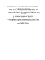
For E2 type ........................................................................................................................................................ 175
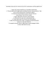
For J2 type ......................................................................................................................................................... 176
For J2-A type ..................................................................................................................................................... 177
Note on the connection of the cables ............................................................................................................. 179
Checking the light illumination ....................................................................................................................... 179


7
IMPORTANT NOTICE
IMPORTANT NOTICE
•
This dealer's manual is intended primarily for use by professional bicycle mechanics.
Users who are not professionally trained for bicycle assembly should not attempt to install the components themselves using the dealer's manuals.
If any part of the information on the manual is unclear to you, do not proceed with the installation. Instead, contact your place of purchase or a local
bicycle dealer for their assistance.
•
Make sure to read all instruction manuals included with the product.
•
Do not disassemble or modify the product other than as stated in the information contained in this dealer's manual.
•
All manuals and technical documents are accessible online at https://si.shimano.com.
•
For consumers who do not have easy access to the internet, please contact a SHIMANO distributor or any of the SHIMANO offices to obtain a hardcopy
of the User's Manual.
•
Please observe the appropriate rules and regulations of the country, state or region in which you conduct your business as a dealer.
For safety, be sure to read this dealer's manual thoroughly before use, and follow it for correct use.
The following instructions must be observed at all times in order to prevent personal injury and physical damage to equipment and surroundings.
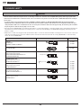
The instructions are classified according to the degree of danger or damage which may occur if the product is used incorrectly.
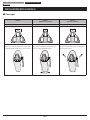
DANGER
Failure to follow the instructions will result in death or serious injury.
WARNING
Failure to follow the instructions could result in death or serious injury.
CAUTION
Failure to follow the instructions could cause personal injury or physical damage to equipment and surroundings.

8
TO ENSURE SAFETY
TO ENSURE SAFETY
WARNING
•
Be sure to follow the instructions provided in the manuals when installing the product.
It is recommended to use genuine Shimano parts only. If parts such as bolts and nuts become loose or damaged, the bicycle may suddenly fall over,
which may cause serious injury.
In addition, if adjustments are not carried out correctly, problems may occur, and the bicycle may suddenly fall over, which may cause serious injury.
•
Be sure to wear safety glasses or goggles to protect your eyes while performing maintenance tasks such as replacing parts.
NOTICE
•
Products are not guaranteed against natural wear and deterioration from normal use and aging.
•
For maximum performance we highly recommend Shimano lubricants and maintenance products.

REAR DERAILLEUR

10
REAR DERAILLEUR TO ENSURE SAFETY
TO ENSURE SAFETY
WARNING
•
Obtain and read the dealer’s manual carefully prior to installing the parts.
Loose, worn or damaged parts may cause the bicycle to fall over and serious injury may occur as a result. It is strongly recommended using only
genuine Shimano replacement parts.
•
Obtain and read the dealer’s manual carefully prior to installing the parts.
If adjustments are not carried out correctly, the chain may come off. This may cause you to fall off the bicycle which could result in serious injury.
NOTICE
•
If gear shifting operations cannot be carried out smoothly, clean the derailleur and lubricate all moving parts.
•
If the amount of looseness in the links is so great that adjustment is not possible, you should replace the derailleur.
•
Grease the inner cable and the inside of the outer casing before use to ensure that they slide properly.
•
For smooth operation, use the specified outer casing and the bottom bracket cable guide.
•
Periodically clean the derailleur and lubricate all moving parts (mechanism and pulleys).
•
If gear shifting adjustment cannot be carried out, check the degree of parallelism at the rear end of the bicycle. Also, check if the cable is lubricated
and if the outer casing is not too long or short.
•
If you hear abnormal noise as a result of looseness in a pulley, you should replace the pulley.
•
A high cable resistance on a frame with internal cable routing could impair the SIS shifting function.
If some resistance is felt in the lever operation, SIS shifting does not function normally, or there is some other issue, check that there is no problem
with the condition of the inner cable or the bending of the outer casing.
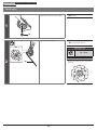
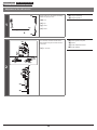
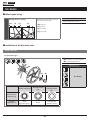
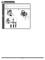
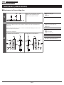
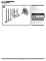
For MTB/Trekking
•
The gears should be periodically washed with a neutral detergent. In addition, cleaning the chain with neutral detergent and lubricating it can be an
effective way of extending the life of the gears and the chain.
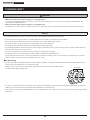
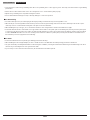
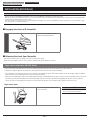
•
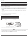
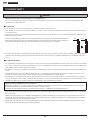
Always be sure to use the sprocket set bearing the same group marks, and never use in combination with a
sprocket bearing a different group mark.
g
a
-
18
T
-
S
H
I
M
A
N
O
H
Y
P
E
R
G
L
I
D
E
C
a
g
-
1
5
T
a
g
-
1
3
T
Group marks
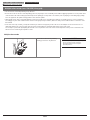
•
Use an outer casing which still has some length to spare even when the handlebars are turned all the way to both sides. Furthermore, check that the
shifting lever does not touch the bicycle frame when the handlebars are turned all the way.
•
A special grease is used for the gear shifting cable. Do not use premium grease or other types of grease. These may cause deterioration in gear shifting
performance.

11
REAR DERAILLEUR TO ENSURE SAFETY
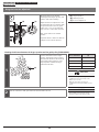
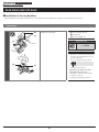
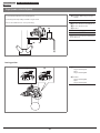
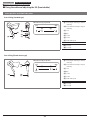
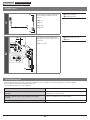
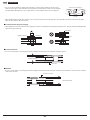
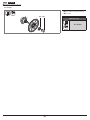
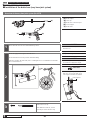
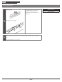
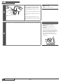
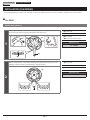
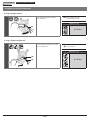
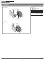
For ROAD
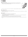
•
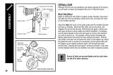
The end of the outer casing which has the aluminum cap should be at the
derailleur side.
Aluminum cap Plastic cap
Aluminum cap (4 mm)
Derailleur side
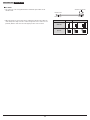
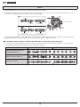
•
When the chain is in any of the position combinations shown in the table, the
chain and sprocket may come into contact and generate noise. If the noise is a
problem, shift the chain onto the next largest sprocket or the one after.
Double Triple
Chainring
Sprocket

12
REAR DERAILLEUR REAR DERAILLEUR FOR MTB/TREKKING
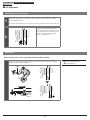
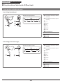
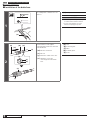
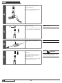
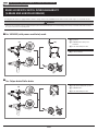
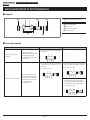
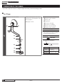
Installation of the rear derailleur
REAR DERAILLEUR FOR MTB/TREKKING
Installation of the rear derailleur
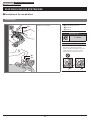
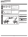
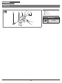
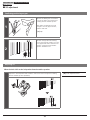
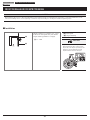
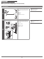
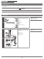
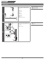
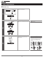
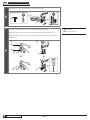
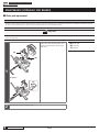
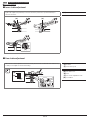
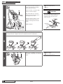
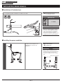
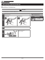
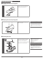
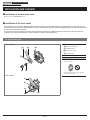
Standard type
(A)
(C)
(B)
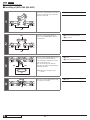
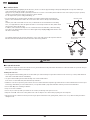
Install the rear derailleur.
(A)
5 mm hexagon wrench
(B)
Dropout
(C)
Bracket
Tightening torque
8 - 10 N·m
NOTICE
Periodically check that there is no gap
between the derailleur hanger and the
bracket as shown in the illustration. If there is
a gap between these two parts, problems
with gear shifting performance may occur.

13
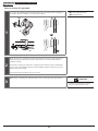
REAR DERAILLEUR REAR DERAILLEUR FOR MTB/TREKKING
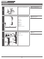
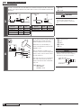
Installation of the rear derailleur
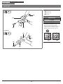
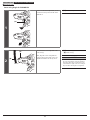
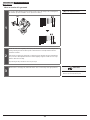
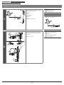
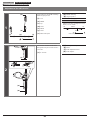
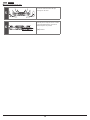
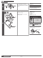
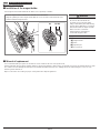
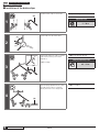
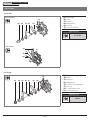
Bracket type
(B) (D)
(A)
(C)
For BMX type
(D)
(A)
(B)
(C)
(A)
Dropout
(B)
Bracket bolt
(C)
Bracket nut
(D)
Bracket
Tightening torque
3 - 4 N·m
NOTICE
Periodically check that there is no gap
between the derailleur hanger and the
bracket as shown in the illustration. If there is
a gap between these two parts, problems
with gear shifting performance may occur.

14
REAR DERAILLEUR REAR DERAILLEUR FOR MTB/TREKKING
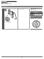
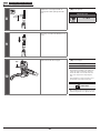
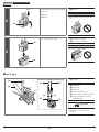
Stroke adjustment
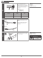
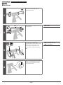
Stroke adjustment
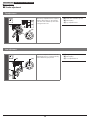
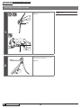
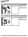
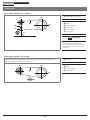
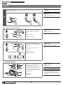
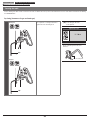
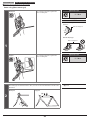
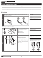
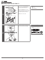
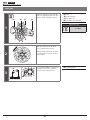
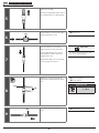
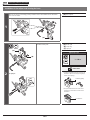
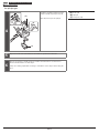
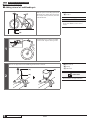
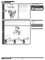
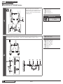
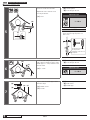
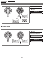
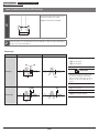
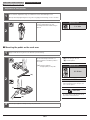
Top adjustment
B
A
B
A
(A)
(B)
(C)
Turn the top adjustment bolt to adjust so
that the guide pulley is in line with the
outer line of the smallest sprocket when
looking from the rear.
(A)
Outer line of smallest sprocket
(B)
Guide pulley
(C)
Top adjustment bolt
Low adjustment
B
A
B
A
(B)
(C)(A)
Turn the low adjustment bolt so that the
guide pulley moves to a position directly
in line with the largest sprocket.
(A)
Largest sprocket
(B)
Guide pulley
(C)
Low adjustment bolt

15
REAR DERAILLEUR REAR DERAILLEUR FOR MTB/TREKKING
Stroke adjustment
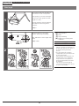
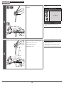
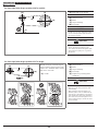
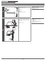
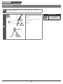
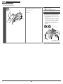
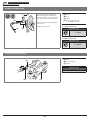
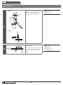
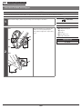
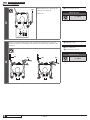
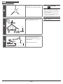
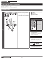
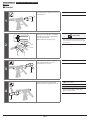
Chain length
1
(z)
(z)
The length of A will vary depending on
the movement of the rear suspension.
Consequently, an excessive load may be
placed on the drive system if the chain
length is too short.
The rear suspension operates and stops
when dimension A is at its greatest
extension.
(z)
A
2
+
(z)
(C)(A)
(B)
Mount the chain on to the largest
sprocket and the largest chainring.
Next, add 2 links to set the length of the
chain.
(z)
+2 links
(A)
Largest sprocket
(B)
Chain
(C)
Largest chainring
(D)
Pin/plate for preventing chain
derailment
NOTICE
•
If there is a lot of movement in the rear
suspension, the slack in the chain may not
be taken up properly when the chain is on
the smallest chainring and smallest
sprocket.
•
The rear derailleur plate assembly is
equipped with a pin or plate that prevents
the chain from derailing.
When passing the chain through the rear
derailleur, pass it to the rear derailleur
body from the side of the pin/plate for
preventing chain derailment as shown in
the illustration.
If the chain is not passed through the
correct position, damage may be caused to
the chain or rear derailleur.
(D)
(D)

16
REAR DERAILLEUR REAR DERAILLEUR FOR MTB/TREKKING
Securing the cable
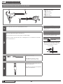
Securing the cable
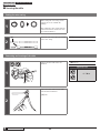
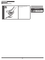
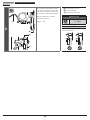
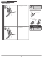
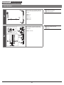
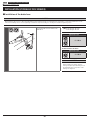
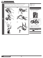
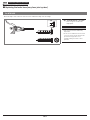
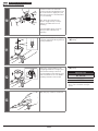
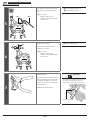
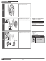
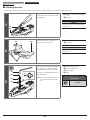
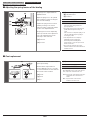
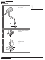
Cutting the outer casing
1
When cutting the outer casing, cut the
end opposite to the end with the
marking.
After cutting the outer casing, make the
end round so that the inside of the hole
has a uniform diameter.
2
(A)
After cutting, attach the same sealed
outer cap to the end.
(A)
Outer cap
3
Install the sealed outer cap with tongue and the rubber shield onto the outer casing stopper
of the frame.
(z)
Be careful not to bend this
section.
(A)
Sealed outer cap with tongue
(B)
Rubber shield
TECH TIPS
If the rear derailleur moves to a large degree,
such as in bicycles with rear suspension, it is
recommended that you replace the cap with
the accessory aluminum cap.
(B)
(B)
(A)
(z)

17
REAR DERAILLEUR REAR DERAILLEUR FOR MTB/TREKKING
Securing the cable
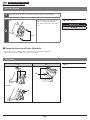
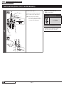
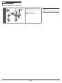
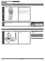
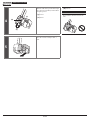
Outer casing length for SHADOW RD
1
(A)
If there is a B-tension adjust bolt, loosen
it until it is in the position shown in the
illustration.
(A)
B-tension adjust bolt
2
(A)
(B)
Check that there is enough slack in the
outer casing.
Next, align the outer casing with the
bottom edge of the holder on the rear
derailleur and then cut off any excess.
(A)
Outer casing holder
(B)
Outer casing
NOTICE
The distance between the outer stopper to
the outer casing holder of the rear derailleur
may change when the rear suspension moves,
so determine the length of the outer casing at
the point where this length is at its greatest.

18
To be continued on next page
REAR DERAILLEUR REAR DERAILLEUR FOR MTB/TREKKING
Securing the cable
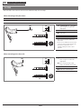
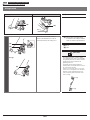
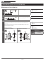
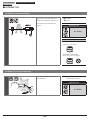
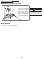
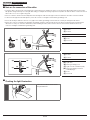
Connecting and securing of the cable
1
(A)
(A)
Connect the inner cable to the rear
derailleur.
(A)
Groove
2
(z)
Remove the initial slack from the cable
as shown in the illustration.
(z)
Pull

19
REAR DERAILLEUR REAR DERAILLEUR FOR MTB/TREKKING
Securing the cable
3
(A)
(A)
Reconnect the inner cable to the rear
derailleur.
(A)
Groove
Tightening torque
6 - 7 N·m
NOTICE
Be sure that the cable is securely in the
groove.
4
(z)
(z)
Set the inner cable so that the margin is
approximately 30 mm or less.
Install the shift inner cap.
(z)
30 mm or less
NOTICE
Check that the inner cable does not interfere
with the wheel spokes.
Stop the wheel from turning while carrying
out this step.

20
REAR DERAILLEUR REAR DERAILLEUR FOR MTB/TREKKING
Securing the cable
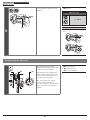
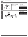
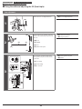
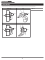
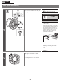
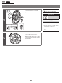
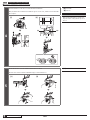
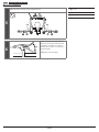
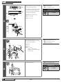
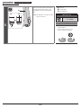
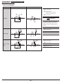
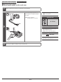
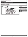
Using the B-tension adjust bolt
B
A
A
A
B
B
(C)(B)
(A)
Mount the chain on the smallest
chainring and the largest sprocket, and
turn the crank arm for shifting.
Adjust the B-tension adjust bolt so that
the guide pulley does not interfere with
the sprocket but do not let the guide
pulley come so close to the chain that
they come into contact with each other.
Next, set the chain on the smallest
sprocket.
Repeat the above to make sure that the
pulley does not touch the sprocket.
(A)
Largest sprocket
(B)
Smallest sprocket
(C)
B-tension adjust bolt
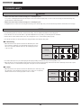
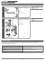
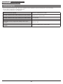
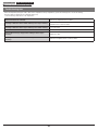
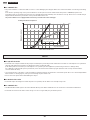
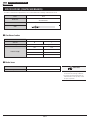
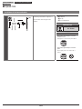
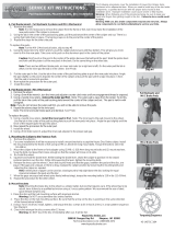
Checking the distance between the largest sprocket and the guide pulley (SHADOW RD)
1
[A]
Set the rear derailleur to the largest
sprocket and, with the wheel stopped,
check that the distance between the tip
of the guide pulley and the tip of the
largest sprocket is within the range
indicated in the table.
Gear combination [A]
11-42T 5 – 6 mm
11-36T 5 – 6 mm
11-34T 5 – 6 mm
11-32T 9 – 10 mm
TECH TIPS
When the lower gear uses the gear
combination of 42T, 36T, or 34T, set the
distance to 5 to 6 mm.
When the lower gear uses the gear
combination of 32T, set the distance to 9 to
10 mm.
2
Turn the crank arm to shift gears and ensure that the shift is smooth.
NOTICE
If the number of teeth for the cassette
sprocket is changed, try setting it again.
Page is loading ...
Page is loading ...
Page is loading ...
Page is loading ...
Page is loading ...
Page is loading ...
Page is loading ...
Page is loading ...
Page is loading ...
Page is loading ...
Page is loading ...
Page is loading ...
Page is loading ...
Page is loading ...
Page is loading ...
Page is loading ...
Page is loading ...
Page is loading ...
Page is loading ...
Page is loading ...
Page is loading ...
Page is loading ...
Page is loading ...
Page is loading ...
Page is loading ...
Page is loading ...
Page is loading ...
Page is loading ...
Page is loading ...
Page is loading ...
Page is loading ...
Page is loading ...
Page is loading ...
Page is loading ...
Page is loading ...
Page is loading ...
Page is loading ...
Page is loading ...
Page is loading ...
Page is loading ...
Page is loading ...
Page is loading ...
Page is loading ...
Page is loading ...
Page is loading ...
Page is loading ...
Page is loading ...
Page is loading ...
Page is loading ...
Page is loading ...
Page is loading ...
Page is loading ...
Page is loading ...
Page is loading ...
Page is loading ...
Page is loading ...
Page is loading ...
Page is loading ...
Page is loading ...
Page is loading ...
Page is loading ...
Page is loading ...
Page is loading ...
Page is loading ...
Page is loading ...
Page is loading ...
Page is loading ...
Page is loading ...
Page is loading ...
Page is loading ...
Page is loading ...
Page is loading ...
Page is loading ...
Page is loading ...
Page is loading ...
Page is loading ...
Page is loading ...
Page is loading ...
Page is loading ...
Page is loading ...
Page is loading ...
Page is loading ...
Page is loading ...
Page is loading ...
Page is loading ...
Page is loading ...
Page is loading ...
Page is loading ...
Page is loading ...
Page is loading ...
Page is loading ...
Page is loading ...
Page is loading ...
Page is loading ...
Page is loading ...
Page is loading ...
Page is loading ...
Page is loading ...
Page is loading ...
Page is loading ...
Page is loading ...
Page is loading ...
Page is loading ...
Page is loading ...
Page is loading ...
Page is loading ...
Page is loading ...
Page is loading ...
Page is loading ...
Page is loading ...
Page is loading ...
Page is loading ...
Page is loading ...
Page is loading ...
Page is loading ...
Page is loading ...
Page is loading ...
Page is loading ...
Page is loading ...
Page is loading ...
Page is loading ...
Page is loading ...
Page is loading ...
Page is loading ...
Page is loading ...
Page is loading ...
Page is loading ...
Page is loading ...
Page is loading ...
Page is loading ...
Page is loading ...
Page is loading ...
Page is loading ...
Page is loading ...
Page is loading ...
Page is loading ...
Page is loading ...
Page is loading ...
Page is loading ...
Page is loading ...
Page is loading ...
Page is loading ...
Page is loading ...
Page is loading ...
Page is loading ...
Page is loading ...
Page is loading ...
Page is loading ...
Page is loading ...
Page is loading ...
Page is loading ...
Page is loading ...
Page is loading ...
Page is loading ...
Page is loading ...
Page is loading ...
Page is loading ...
Page is loading ...
Page is loading ...
Page is loading ...
Page is loading ...
Page is loading ...
-
 1
1
-
 2
2
-
 3
3
-
 4
4
-
 5
5
-
 6
6
-
 7
7
-
 8
8
-
 9
9
-
 10
10
-
 11
11
-
 12
12
-
 13
13
-
 14
14
-
 15
15
-
 16
16
-
 17
17
-
 18
18
-
 19
19
-
 20
20
-
 21
21
-
 22
22
-
 23
23
-
 24
24
-
 25
25
-
 26
26
-
 27
27
-
 28
28
-
 29
29
-
 30
30
-
 31
31
-
 32
32
-
 33
33
-
 34
34
-
 35
35
-
 36
36
-
 37
37
-
 38
38
-
 39
39
-
 40
40
-
 41
41
-
 42
42
-
 43
43
-
 44
44
-
 45
45
-
 46
46
-
 47
47
-
 48
48
-
 49
49
-
 50
50
-
 51
51
-
 52
52
-
 53
53
-
 54
54
-
 55
55
-
 56
56
-
 57
57
-
 58
58
-
 59
59
-
 60
60
-
 61
61
-
 62
62
-
 63
63
-
 64
64
-
 65
65
-
 66
66
-
 67
67
-
 68
68
-
 69
69
-
 70
70
-
 71
71
-
 72
72
-
 73
73
-
 74
74
-
 75
75
-
 76
76
-
 77
77
-
 78
78
-
 79
79
-
 80
80
-
 81
81
-
 82
82
-
 83
83
-
 84
84
-
 85
85
-
 86
86
-
 87
87
-
 88
88
-
 89
89
-
 90
90
-
 91
91
-
 92
92
-
 93
93
-
 94
94
-
 95
95
-
 96
96
-
 97
97
-
 98
98
-
 99
99
-
 100
100
-
 101
101
-
 102
102
-
 103
103
-
 104
104
-
 105
105
-
 106
106
-
 107
107
-
 108
108
-
 109
109
-
 110
110
-
 111
111
-
 112
112
-
 113
113
-
 114
114
-
 115
115
-
 116
116
-
 117
117
-
 118
118
-
 119
119
-
 120
120
-
 121
121
-
 122
122
-
 123
123
-
 124
124
-
 125
125
-
 126
126
-
 127
127
-
 128
128
-
 129
129
-
 130
130
-
 131
131
-
 132
132
-
 133
133
-
 134
134
-
 135
135
-
 136
136
-
 137
137
-
 138
138
-
 139
139
-
 140
140
-
 141
141
-
 142
142
-
 143
143
-
 144
144
-
 145
145
-
 146
146
-
 147
147
-
 148
148
-
 149
149
-
 150
150
-
 151
151
-
 152
152
-
 153
153
-
 154
154
-
 155
155
-
 156
156
-
 157
157
-
 158
158
-
 159
159
-
 160
160
-
 161
161
-
 162
162
-
 163
163
-
 164
164
-
 165
165
-
 166
166
-
 167
167
-
 168
168
-
 169
169
-
 170
170
-
 171
171
-
 172
172
-
 173
173
-
 174
174
-
 175
175
-
 176
176
-
 177
177
-
 178
178
-
 179
179
-
 180
180
-
 181
181
-
 182
182


Ask a question and I''ll find the answer in the document
Finding information in a document is now easier with AI
Related papers
-
Shimano RD-M280 Dealer's Manual
-
Shimano FH-MC10-NT Exploded View
-
-
-
-
-
-
Shimano BR-RS405 Dealer's Manual
-
Shimano FD-T6000 Dealer's Manual
-
Shimano SM-BB90 Service Instructions
Other documents
-
 Ventura 230315 Operating instructions
-
Pioneer SGY-PM910H Owner's manual
-
 Vuelta 868001104 Operating instructions
-
 Babbitt Steam Specialty CIRG-1.5 Installation guide
-
 Ocean City Cruisers CFKM-008 Operating instructions
-
 Ventura 230815 Operating instructions
-
 Ventura 230170 Operating instructions
-
 Ventura 233855 Operating instructions
-
 Tour de France 302210 Operating instructions
-
 HAYES DISC BRAKES GENERAL-45-14575B Owner's manual


