SI-8G70C-001-00
General Safety Information
SI-8G70C-001
BR-IM81-F
BR-IM80-F
BR-IM55-F
BR-IM45-F
Inter-M Brake
Technical Service Instructions
In order to realize the best performance from the Shimano
front Inter-M brake system, we recommend that the following
combination be used.
Brake BR-IM81-F
BR-IM80-F
BR-IM55-F/
BR-IM45-F
Hub HB-IM70/
DH-2R35-E-H/
DH-3R35-H
HB-IM40/
DH-2R35-E/
DH-3R35/
DH-2R30-J
Lever
SB-8S20/ST-8S20/SB-7S45/
BL-IM60/BL-IM65/BL-IM45
Brake cable
Installing the brake cable
After checking that the adjusting bolt and adjusting nut are
1.
fully tightened, insert the outer casing holder unit into the
inner cable in the direction shown below.
Outer casing holder unit
Adjusting nut
Adjusting bolt
After checking that the stamp of the back side of the inner
2.
cable fixing bolt unit is “F”, pass the inner cable through
the hole of the inner cable fixing bolt unit.
Stamp “F”
Inner cable fixing bolt unit
Place the components as shown in the following figure
3.
and tighten the inner cable fixing nut. Use the TL-IM21
(inner cable fixing tool) to tighten the inner cable fixing
nut as shown in Fig. 1. After tightening, check that the
orientations of the inner cable fixing nut and inner cable
are correct as shown in Fig. 2.
109mm
Fig. 1
TL-IM21
Inner cable
fixing nut
Tightening torque:
6 – 8 N·m {52 – 70 in. lbs.}
Fig. 2
Never tighten the inner cable fixing bolt with it attached to
your bicycle. The orientations of the inner cable fixing nut
and inner cable will become improper as shown in Fig. 3,
which may cause the inner cable fixing bolt to detach from
the brake.
Fig. 3
Align the red mark on the inner cable fixing washer so that
4.
it faces in the direction of the groove in the winder unit,
and then insert the inner cable fixing bolt unit and push it
into the groove in the winder unit as far as it will go.
Inner cable fixing bolt unit
Insert the inner cable fixing
bolt unit into the groove in the
winder unit as far as it will go.
Groove in winder unit
Red mark on
inner cable
fixing washer
Route the inner cable along the groove of the winder unit.
5.
Inner cableGroove of winder unit
Hook the inner cable over the cable hook.
6.
Inner cable
Cable hook
Insert the outer casing holder unit into the hole of the
7.
brake arm from underneath and slide it to the lower
section of the hole.
Brake arm
Outer casing
holder unit
After checking that the outer casing holder unit is securely
8.
inserted into the back of the brake arm hole, attach the
inner end cap.
Then, set the inner end cap so that it does not touch the
fin or the spokes.
Outer casing
holder unit
Inner end cap
Turn the cable adjusting bolt to tighten the inner cable.
9.
Cable adjusting bolt
Check that the red marks on inner cable fixing washer
10.
with the inner cable fixing bolt unit press-fit into the winder
unit are in the right orientation.
Red mark
Red mark
Installation of the brake cable can be completed by the
above procedure. When detaching the cable, perform in
reverse order.
Adjusting the brake cable
After checking that the wheel does not easily turn while
1.
the brake cable is being pulled, depress the brake lever
about 10 times as far as the grip in order to run in the
brake cable.
Depress
about
10 times
Note:
If the brake cable is not run in, it will need to be
adjusted again after only a short period of use.
Turn the cable adjusting bolt of the brake unit or brake
2.
lever so that there is about 15 mm of play in the brake
lever.
The amount of brake lever play is the distance from
the position where the brake lever is not operated to
the position where a force is felt suddenly when the
brake lever is pulled.
Cable adjusting bolt
15mm of play
Cable adjusting bolt
After depressing the brake lever to check the braking
3.
performance, secure the cable adjusting bolt with the
cable adjusting nut.
Cable adjusting nut
Tightening torque:
1 – 2 N·m {9 – 17 in. lbs.}
WARNING
– To avoid serious injuries:
It is important to completely understand the operation ●
of your bicycle’s brake system. Improper use of your
bicycle’s brake system may result in a loss of control
or an accident, which could lead to severe injury.
Because each bicycle may handle differently, be sure
to learn the proper braking technique (including brake
lever pressure and bicycle control characteristics) and
operation of your bicycle.
This can be done by consulting your professional
bicycle dealer and the bicycle’s owners manual, and
by practicing your riding and braking technique.
If the front brake is applied too strongly, the wheel ●
may lock and the bicycle may fall forward, and
serious injury may result.
The hub of the Shimano front Inter-M brake has a ●
built-in power modulator. This system controls the
braking force so that excessive force is not applied
if the braking force reaches the specified value. If
the hub is not equipped with the power modulator,
the braking force may be excessively applied. For
this reason, we recommend using the Shimano
front Inter-M brake and the hub as a set. Noise is
generated by the operation of the power modulator
when the brake is applied, but this is not a sign of a
malfunction.
Never tighten the inner cable fixing bolt with it ●
attached to your bicycle. Doing so may cause the
inner cable fixing bolt to detach.
If using the BR-IM81-F, BR-IM80-F, BR-IM55-F, ●
BR-IM45-F in combination with a suspension fork,
care must be taken when selecting the suspension
fork to use. Please consult with the shop or the
bicycle manufacturer. If an incorrect type of
suspension fork is selected, it could prevent the
suspension fork from functioning properly because of
overheating during braking or lack of strength in the
fork, which could result in an accident.
The SB-8S20/ST-8S20/SB-7S45/BL-IM60/BL-IM65/ ●
BL-IM45 brake levers are equipped with a mode
switching mechanism. Be sure to use the BR-IM81-F,
BR-IM80-F, BR-IM55-F, BR-IM45-F with the
mechanism in the C.R. mode position.
C.R mode position
The C indicates the mode position for
compatibility with cantilever brakes.
The R indicates the mode position for
compatibility with roller brakes.
● Obtain and read the service instructions carefully
prior to installing the parts. Loose, worn, or
damaged parts may cause serious injury to the rider.
We strongly recommend only using genuine Shimano
replacement parts.
Always make sure that the front and rear brakes are ●
working correctly before you ride the bicycle.
If the road surface is wet, the tires will skid more ●
easily. If the tires skid, you may fall off the bicycle. To
avoid this, reduce your speed and apply the brakes
early and gently.
Read these Technical Service Instructions carefully, ●
and keep them in a safe place for later reference.
CAUTION
– To avoid serious injuries:
When using the Shimano Inter-M brake system, avoid
1.
continuous application of the brakes when riding down
long slopes, as this will cause the internal brake parts
to become very hot, and this may weaken braking
performance. It may also cause a reduction in the
amount of brake grease inside the brake, and this can
lead to problems such as abnormally sudden braking.
The design of the Shimano Inter-M brake system has
been carried out based on standards such as ISO
4210 and DIN 79100-2. These standards specify the
performance for an overall weight of 100 kg. However,
BR-IM81-F is designed with the overall weight assumed
to be 130kg. If the overall weight exceeds 100 kg (130kg
for BR-IM81-F), the braking force provided by the system
may be insufficient for correct braking, and durability of
the system may also be reduced.
The front Inter-M brake system should only be installed
2.
to the left side of a bicycle which is 26” or larger. If it is
used on a bicycle which is smaller than 26”, the braking
force may be too great, which could cause accidents.
In order to get the best performance from the Shimano
3.
front Inter-M brake, be sure to use Shimano brakes
cables and brake levers as a set. (Refer to the product
line-up.)
The amount of movement of the inner cable must be
14.5 mm or more when the brake lever is depressed.
If it is less than 14.5 mm, braking performance will
suffer, and the brakes may fail to work.
Check that the front brake unit is firmly secured to the
4.
hub with the brake unit fixing nut.
Brake unit fixing nut
In case of the quick release ●
type:
With rollets
Surface with rollets should
be facing outward
In case of the hub nut type: ●
without rollets
Brake unit
Tightening torque:
15 – 20 N·m {131 – 174 in. lbs.}
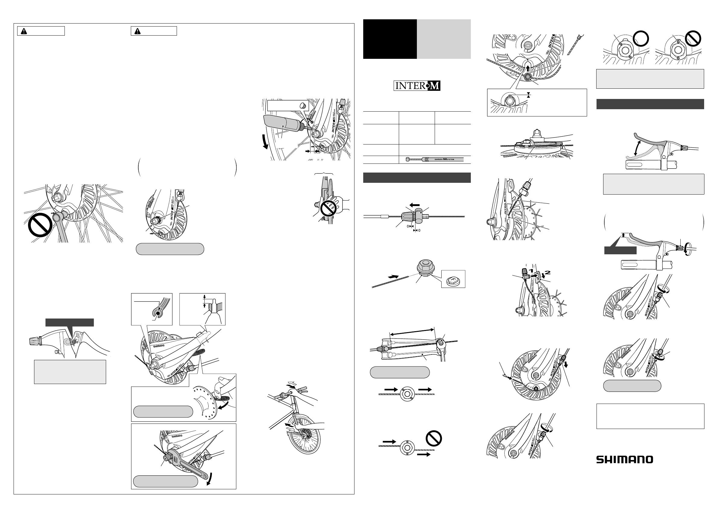
Check that the hub axle is touching the back of the fork
5.
end, and that the end of the brake arm is protruding 11
mm or more from the brazed-on bracket of the front fork.
Check also that the wheel is firmly secured to the frame
with the quick release or the hub nut. If the wheel is not
installed properly, it may come off the frame, which could
result in a serious accident when riding.
Tightening torque:
20 – 25 N·m {174 – 218 in. lbs.}
In case of the nut type: ●
Hub nut
In case of the quick release type: ●
Secure the cam lever of the
quick release firmly.
Tightening torque:
5 – 7.5 N·m {44 – 65 in. lbs.}
11mm or
more
Touching
Brazed-on
bracket
Hub axle
If any of the following occur while using the brakes, stop
6.
riding immediately and ask the place of purchase to carry
out inspection and repairs.
1) If abnormal noise is heard when the brakes are
applied
2) If braking force is abnormally strong
3) If braking force is abnormally weak
In the case of 1) and 2), the cause might be not enough
brake grease, so ask the place of purchase to grease the
mechanism with special roller brake grease.
Before applying grease, remove the grease hole cap
and press-fit the tube into the back of the hole. Apply an
appropriate amount of grease (approx. 5g) while turning
the wheel slowly. After application, check that braking is
properly applied and that no abnormal noise is heard.
Grease hole cap
Turn
slowly.
12mm or more
Grease for
roller brake
If the brakes are used
7.
frequently, the components
around the brake may
become hot. Do not touch the
components for at least 30
minutes after you finish riding
the bicycle.
If the brake cable becomes rusted, braking performance
8.
will suffer. If this happens, replace the brake cable with a
genuine Shimano brake cable and re-check the braking
performance.
The front brake unit, front hub units should never be
9.
disassembled. If they are disassembled, it will no longer
work properly.
NOTE:
Use a wheel with 3x or 4x spoke lacing. Wheels with ●
radial lacing cannot be used because the spokes and the
wheel can be damaged when applying the brakes and
brake noise can be generated.
The front Inter-M brake is different from conventional ●
band brakes in that the inside of the brake drum is filled
with grease. This may cause the turning of the wheel to
be slightly heavier than usual, particularly in cold weather.
If you apply the front Inter-M brake strongly while the ●
bicycle is stopped and then shake the wheel, you will
notice that there is a small amount of play in the brakes.
This is normal, and will not cause any problems at all
while riding.
To check the amount of looseness in the head parts, ●
grasp the middle of the handlebar and one of the front
forks as shown in the illustration, and then move the head
parts back and forth in the directions indicated by the
arrows.
Moreover, because the brakes give a small amount of
play if you apply the brakes fully and shake the wheel as
described above, this will make it more difficult to check
the looseness in the head parts.
Parts are not guaranteed against natural wear or ●
deterioration resulting from normal use.
For maximum performance we highly recommend ●
Shimano lubricants and maintenance products.
For any questions regarding methods of handling or ●
adjustment, please contact the place of purchase.
Components
around the brake
These service instructions explain how to use and maintain
the Shimano bicycle parts which have been used on your new
bicycle. For any questions regarding your bicycle or other
matters which are not related to Shimano parts, please contact
the place of purchase or the bicycle manufacturer.
* Service Instructions in further languages are available at:
http://techdocs.shimano.com
Please note: specifications are subject to change for improvement
without notice. (English)
3-77 Oimatsu-cho, Sakai-ku, Sakai-shi, Osaka 590-8577, Japan
Industrieweg 24, 8071 CT Nunspeet, The Netherlands Phone: +31-341-272222
One Holland, Irvine, California 92618, U.S.A. Phone: +1-949-951-5003
SHIMANO AMERICAN CORPORATION
SHIMANO EUROPE B.V.
SHIMANO INC.
© Jun. 2011 by Shimano Inc. AWS. Printed in China

