Page is loading ...

www.rosemount.com
Reference Manual
00809-0100-4028, Rev AA
October 2005
The 285 Annubar
®
Primary Element Series
Product Discontinued December 2009


Reference Manual
00809-0100-4028, Rev AA
October 2005
Rosemount 285
www.rosemount.com
285 Annubar Primary Element Series
NOTICE
Read this manual before working with the product. For personal and system safety, and for
optimum product performance, make sure you thoroughly understand the contents before
installing, using, or maintaining this product.
The United States has two toll-free assistance numbers and one International number.
Customer Central
1-800-999-9307 (7:00 a.m. to 7:00 P.M. CST)
International
1-(952) 906-8888
National Response Center
1-800-654-7768 (24 hours a day)
Equipment service needs
The products described in this document are NOT designed for nuclear-qualified
applications. Using non-nuclear qualified products in applications that require
nuclear-qualified hardware or products may cause inaccurate readings.
For information on Rosemount nuclear-qualified products, contact your local Rosemount
Sales Representative.
This device is intended for use in temperature monitoring applications and should not be
used in control and safety applications.


Reference Manual
00809-0100-4028, Rev AA
October 2005
Rosemount 285
www.rosemount.com
Table of Contents
SECTION 1
Introduction
Using This Manual . . . . . . . . . . . . . . . . . . . . . . . . . . . . . . . . . . . . . . . . 1-1
Section 2: Installation . . . . . . . . . . . . . . . . . . . . . . . . . . . . . . . . 1-1
Section 3: Commissioning. . . . . . . . . . . . . . . . . . . . . . . . . . . . . 1-1
Section 4: Operation and Maintenance . . . . . . . . . . . . . . . . . . . 1-1
Appendix A: Specifications and Reference Data. . . . . . . . . . . . 1-1
Appendix B: Approvals . . . . . . . . . . . . . . . . . . . . . . . . . . . . . . . 1-1
Receiving and Inspection. . . . . . . . . . . . . . . . . . . . . . . . . . . . . . . . . . . 1-2
Returning the Product . . . . . . . . . . . . . . . . . . . . . . . . . . . . . . . . . . . . . 1-2
Considerations. . . . . . . . . . . . . . . . . . . . . . . . . . . . . . . . . . . . . . . . . . . 1-2
Limitations . . . . . . . . . . . . . . . . . . . . . . . . . . . . . . . . . . . . . . . . . . . 1-2
Structural . . . . . . . . . . . . . . . . . . . . . . . . . . . . . . . . . . . . . . . . . . 1-2
Functional . . . . . . . . . . . . . . . . . . . . . . . . . . . . . . . . . . . . . . . . . 1-2
Environmental. . . . . . . . . . . . . . . . . . . . . . . . . . . . . . . . . . . . . . . . . 1-3
Access Requirements . . . . . . . . . . . . . . . . . . . . . . . . . . . . . . . . 1-3
Process Flange Orientation. . . . . . . . . . . . . . . . . . . . . . . . . . . . 1-3
Optional Electronics Housing . . . . . . . . . . . . . . . . . . . . . . . . . . 1-3
Cover Installations. . . . . . . . . . . . . . . . . . . . . . . . . . . . . . . . . . . 1-3
Process Considerations . . . . . . . . . . . . . . . . . . . . . . . . . . . . . . . . . 1-4
Electrical . . . . . . . . . . . . . . . . . . . . . . . . . . . . . . . . . . . . . . . . . . . . . 1-4
SECTION 2
Installation
Safety Messages . . . . . . . . . . . . . . . . . . . . . . . . . . . . . . . . . . . . . . . . . 2-1
Installation Flowchart and Checklist . . . . . . . . . . . . . . . . . . . . . . . . . . 2-2
Mounting . . . . . . . . . . . . . . . . . . . . . . . . . . . . . . . . . . . . . . . . . . . . . . . 2-4
Tools and Supplies . . . . . . . . . . . . . . . . . . . . . . . . . . . . . . . . . . . . . 2-4
Mounting Brackets . . . . . . . . . . . . . . . . . . . . . . . . . . . . . . . . . . . . . 2-4
Bolt Installation Guidelines . . . . . . . . . . . . . . . . . . . . . . . . . . . . . . . 2-4
Instrument Manifolds . . . . . . . . . . . . . . . . . . . . . . . . . . . . . . . . . . . 2-5
Straight Run Requirements . . . . . . . . . . . . . . . . . . . . . . . . . . . . . . 2-6
Direct Mount . . . . . . . . . . . . . . . . . . . . . . . . . . . . . . . . . . . . . . . . . . 2-8
Horizontal Pipes . . . . . . . . . . . . . . . . . . . . . . . . . . . . . . . . . . . . 2-8
Vertical Pipes . . . . . . . . . . . . . . . . . . . . . . . . . . . . . . . . . . . . . . 2-9
Remote Mount . . . . . . . . . . . . . . . . . . . . . . . . . . . . . . . . . . . . . . . . 2-9
Valves and Fittings . . . . . . . . . . . . . . . . . . . . . . . . . . . . . . . . . . 2-9
Impulse Piping. . . . . . . . . . . . . . . . . . . . . . . . . . . . . . . . . . . . . 2-10
Installation . . . . . . . . . . . . . . . . . . . . . . . . . . . . . . . . . . . . . . . . . . . . . 2-11
Pak-Lok Model . . . . . . . . . . . . . . . . . . . . . . . . . . . . . . . . . . . . . . . 2-11
Step 1: Determine the Proper Orientation . . . . . . . . . . . . . . . . 2-12
Step 2: Drill a Hole into the Pipe . . . . . . . . . . . . . . . . . . . . . . . 2-12
Step 3: Weld the Mounting Hardware . . . . . . . . . . . . . . . . . . . 2-13
Step 4: Insert into the Pipe . . . . . . . . . . . . . . . . . . . . . . . . . . . 2-14
Step 5: Mount the Transmitter. . . . . . . . . . . . . . . . . . . . . . . . . 2-15
Remote Mount Head – temperatures below 250 °F (121 °C) . 2-15
Remote Mount Head – temperature above 250 °F (121 °C) . . 2-16

Reference Manual
00809-0100-4028, Rev AA
October 2005
Rosemount 285
TOC-2
Duct Model . . . . . . . . . . . . . . . . . . . . . . . . . . . . . . . . . . . . . . . . . . 2-17
Step 1: Determine the Proper Orientation . . . . . . . . . . . . . . . . 2-17
Step 2: Drill a Hole into the Duct . . . . . . . . . . . . . . . . . . . . . . . 2-17
Step 3: Assemble and check Fit-Up . . . . . . . . . . . . . . . . . . . . 2-18
Step 4: Insert into Duct . . . . . . . . . . . . . . . . . . . . . . . . . . . . . . 2-19
Step 5: Mount the Transmitter. . . . . . . . . . . . . . . . . . . . . . . . . 2-21
Remote Mount Head . . . . . . . . . . . . . . . . . . . . . . . . . . . . . . . . 2-22
SECTION 3
Commissioning
Commisioning the 951 transmitter . . . . . . . . . . . . . . . . . . . . . . . . . . . . 3-1
Step 1: Mount the Transmitter . . . . . . . . . . . . . . . . . . . . . . . . . . . . 3-1
Gas Flow Applications . . . . . . . . . . . . . . . . . . . . . . . . . . . . . . . . . . . . . 3-1
Step 2: Connect Wiring and Power Up. . . . . . . . . . . . . . . . . . . . . . 3-2
Power Supply. . . . . . . . . . . . . . . . . . . . . . . . . . . . . . . . . . . . . . . . . . . . 3-2
Step 3: Configure the Transmitter . . . . . . . . . . . . . . . . . . . . . . . . . 3-3
Step 4: Trim the Transmitter. . . . . . . . . . . . . . . . . . . . . . . . . . . . . . 3-3
Zero Trim . . . . . . . . . . . . . . . . . . . . . . . . . . . . . . . . . . . . . . . . . . . . . . . 3-3
Using the 275/375 HART Communicator . . . . . . . . . . . . . . . . . . . . 3-4
Local Re-ranging and Trim . . . . . . . . . . . . . . . . . . . . . . . . . . . . . . . 3-4
Zero - 4 mA point. . . . . . . . . . . . . . . . . . . . . . . . . . . . . . . . . . . . 3-4
Without an LCD meter. . . . . . . . . . . . . . . . . . . . . . . . . . . . . . . . 3-4
With an LCD meter . . . . . . . . . . . . . . . . . . . . . . . . . . . . . . . . . . 3-4
. . . . . . . . . . . . . . . . . . . . . . . . . . . . . . . . . . . . . . . . . . . . . . . . . 3-4
Span - 20 mA point . . . . . . . . . . . . . . . . . . . . . . . . . . . . . . . . . . 3-4
Without an LCD meter. . . . . . . . . . . . . . . . . . . . . . . . . . . . . . . . 3-4
With an LCD meter . . . . . . . . . . . . . . . . . . . . . . . . . . . . . . . . . . 3-4
Safety Messages . . . . . . . . . . . . . . . . . . . . . . . . . . . . . . . . . . . . . . . . . 3-5
Commissioning on the Bench . . . . . . . . . . . . . . . . . . . . . . . . . . . . . . . 3-5
Commissioning the 285 with the 2024 transmitter. . . . . . . . . . . . . . . . 3-6
Direct Mount . . . . . . . . . . . . . . . . . . . . . . . . . . . . . . . . . . . . . . . . . . 3-6
Liquid Service . . . . . . . . . . . . . . . . . . . . . . . . . . . . . . . . . . . . . . 3-6
Liquid Service 3-Valve Manifold . . . . . . . . . . . . . . . . . . . . . . . . 3-6
Gas Service. . . . . . . . . . . . . . . . . . . . . . . . . . . . . . . . . . . . . . . . 3-7
Gas Service 3-Valve Manifold . . . . . . . . . . . . . . . . . . . . . . . . . . 3-8
Wet Zero . . . . . . . . . . . . . . . . . . . . . . . . . . . . . . . . . . . . . . . . . . 3-8
Steam Service . . . . . . . . . . . . . . . . . . . . . . . . . . . . . . . . . . . . . . 3-9
3-Valve Steam No Flow. . . . . . . . . . . . . . . . . . . . . . . . . . . . . . 3-10
Remote Mount . . . . . . . . . . . . . . . . . . . . . . . . . . . . . . . . . . . . . . . 3-10
Zero the Electronics . . . . . . . . . . . . . . . . . . . . . . . . . . . . . . . . 3-10
Check for System Leaks . . . . . . . . . . . . . . . . . . . . . . . . . . . . . 3-11
“Calibrate Out” Temperature Effects . . . . . . . . . . . . . . . . . . . . 3-11
Gas Service. . . . . . . . . . . . . . . . . . . . . . . . . . . . . . . . . . . . . . . 3-13
Steam Service or Liquid Service above 250 °F (121 °C) . . . . 3-14
SECTION 4
Operation and
Maintenance
Safety Messages . . . . . . . . . . . . . . . . . . . . . . . . . . . . . . . . . . . . . . . . . 4-1
Troubleshooting . . . . . . . . . . . . . . . . . . . . . . . . . . . . . . . . . . . . . . . . . . 4-2
Disassembly . . . . . . . . . . . . . . . . . . . . . . . . . . . . . . . . . . . . . . . . . . . . 4-3
Remove the Flowmeter from Service . . . . . . . . . . . . . . . . . . . . . . . 4-3
APPENDIX A
Reference Data
Rosemount 285 Annubar Primary Specifications . . . . . . . . . . . . . . . . A-1
Performance Specifications . . . . . . . . . . . . . . . . . . . . . . . . . . . . . . A-1
Functional Specifications . . . . . . . . . . . . . . . . . . . . . . . . . . . . . . . . A-2
Physical Specifications . . . . . . . . . . . . . . . . . . . . . . . . . . . . . . . . . . A-2

Reference Manual
00809-0100-4028, Rev AA
October 2005
TOC-3
Rosemount 285
Installation Considerations . . . . . . . . . . . . . . . . . . . . . . . . . . . . . . . A-3
Optional Rosemount 2024 Transmitter Specifications. . . . . . . . . . . . . A-7
Performance Specifications . . . . . . . . . . . . . . . . . . . . . . . . . . . . . . A-7
Functional Specifications . . . . . . . . . . . . . . . . . . . . . . . . . . . . . . . . A-7
Physical Specifications . . . . . . . . . . . . . . . . . . . . . . . . . . . . . . . . . . A-9
Calibration . . . . . . . . . . . . . . . . . . . . . . . . . . . . . . . . . . . . . . . . . . . A-9
Optional Rosemount 951 Transmitter Specifications. . . . . . . . . . . . . . A-9
Performance Specifications . . . . . . . . . . . . . . . . . . . . . . . . . . . . . . A-9
Functional Specifications . . . . . . . . . . . . . . . . . . . . . . . . . . . . . . . A-10
Physical Specifications . . . . . . . . . . . . . . . . . . . . . . . . . . . . . . . . . A-11
Dimensional Drawings . . . . . . . . . . . . . . . . . . . . . . . . . . . . . . . . . . . . A-12
Ordering Information . . . . . . . . . . . . . . . . . . . . . . . . . . . . . . . . . . . . . A-15
Rosemount 285 Annubar Primary Ordering Information . . . . A-15
Pipe I.D. Range Code–measured in inches (millimeters). . . . . . . A-17
APPENDIX B
Approvals
Hazardous Locations Installations . . . . . . . . . . . . . . . . . . . . . . . . . . . . B-1
Rosemount 2024 Product Certifications . . . . . . . . . . . . . . . . . . . . . . . B-1
Approved Manufacturing Locations . . . . . . . . . . . . . . . . . . . . . . . . B-1
European Directive Information . . . . . . . . . . . . . . . . . . . . . . . . . . . B-1
Hazardous Locations Certifications . . . . . . . . . . . . . . . . . . . . . . . . B-2

Reference Manual
00809-0100-4028, Rev AA
October 2005
Rosemount 285
TOC-4

Reference Manual
00809-0100-4028, Rev AA
October 2005
Rosemount 285
www.rosemount.com
Section 1 Introduction
Using This Manual . . . . . . . . . . . . . . . . . . . . . . . . . . . . . . . page 1-1
Receiving and Inspection . . . . . . . . . . . . . . . . . . . . . . . . . page 1-2
Returning the Product . . . . . . . . . . . . . . . . . . . . . . . . . . . . page 1-2
Considerations . . . . . . . . . . . . . . . . . . . . . . . . . . . . . . . . . . page 1-2
USING THIS MANUAL This product manual provides installation, configuration, calibration,
troubleshooting, and maintenance instructions for the Annubar Flowmeter
Series.
Section 2: Installation
• Installation flowchart and checklist
• Orienting, mounting, and installing the flowmeter
• Commissioning the flowmeter according to the application
Section 3: Commissioning
• Commissioning on the Bench
• Commissioning the 285 with the 2024 transmitter
Section 4: Operation and Maintenance
• Troubleshooting information
• Disassembly
Appendix A: Specifications and Reference Data
• Specifications
• Dimensional drawings
Appendix B: Approvals
• Approvals certifications

Reference Manual
00809-0100-4028, Rev AA
October 2005
Rosemount 285
1-2
RECEIVING AND
INSPECTION
Annubar Primary Elements are available in different models and with different
options, so it is important to inspect and verify that the appropriate model was
delivered before installation.
Upon receipt of the shipment, check the packing list against the material
received and the purchase order. All items are tagged with a model number,
serial number, and customer tag number. Report any damage to the carrier.
RETURNING THE
PRODUCT
To expedite the return process, call the Rosemount National Response
Center toll-free at 800-654-7768. This center, available 24 hours a day, will
assist you with any needed information or materials.
The center will ask for the following information:
• Product model
• Serial numbers
• The last process material to which the product was exposed
The center will provide
• A Return Material Authorization (RMA) number
• Instructions and procedures that are necessary to return goods that
were exposed to hazardous substances
NOTE
If a hazardous substance is identified, a Material Safety Data Sheet (MSDS),
required by law to be available to people exposed to specific hazardous
substances, must be included with the returned materials.
CONSIDERATIONS Information in this manual applies to circular pipes and square or rectangular
ducts only. Consult Rosemount Customer Central for instructions regarding
use in other duct configurations.
Limitations Structural
Structural limitations are printed on the sensor tag. Exceeding structural
limitations may cause sensor failure.
Functional
The most accurate and repeatable flow measurement occurs in the following
conditions:
• The structural limit differential pressure, as printed on the sensor tag, is
not exceeded.
• The instrument is not used for two-phase flow or for steam service
below saturation temperature.
Install the flowmeter in the correct location within the piping branch to prevent
measurement inaccuracies caused by flow disturbances.
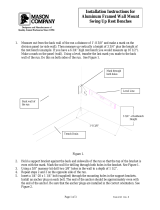
The flowmeter can be installation with a maximum misalignment of 3 degrees
(see Figure 1-1). Misalignment beyond 3 degrees will cause flow
measurement errors.

Reference Manual
00809-0100-4028, Rev AA
October 2005
1-3
Rosemount 285
Figure 1-1. Permissible
Misalignment
Environmental Mount the Annubar Primary Element in a location with minimal ambient
temperature changes. Appendix A: Reference Data lists the temperature
operating limits. Mount to avoid vibration, mechanical shock, and external
contact with corrosive materials.
Access Requirements
Consider the need to access the flowmeter when choosing an installation
location and orientation.
Process Flange Orientation
Orient the process flanges on a remote mounted Annubar Primary Element so
that process connections can be made. For safety reasons, orient the
drain/vent valves so that process fluid is directed away from technicians when
the valves are used. In addition, consider the possible need for a testing or
calibration input.
Optional Electronics Housing
Terminal Side
The circuit compartment should not routinely need to be opened when the
unit is in service. Wiring connections are made through the conduit
openings on the top side of the housing. The field terminal side is marked
on the electronics housing. Mount the flowmeter so that the terminal side
is accessible. A 0.75-in. (19 mm) clearance is required for cover removal.
Use a conduit plug on the unused side of the conduit opening. A 3-in. (76
mm) clearance is required for cover removal if a meter is installed.
Cover Installations
Always install the electronics housing covers metal-to-metal to ensure a
proper seal.
3°
3°
3°
15-490022-901A, 15-490022-902, 15-490022-903.EPS

Reference Manual
00809-0100-4028, Rev AA
October 2005
Rosemount 285
1-4
Figure 1-2. Electronics Housing
Process Considerations The process connections on the 2024 transmitter flange are 1/4–18 NPT.
These are Class 2 threads; use the plant-approved lubricant or sealant when
making the process connections. The process connections on the transmitter
flange are on 2
1
/8–in. (54 mm) centers to allow direct mounting to a three- or
five-valve manifold. The process connections on the 951 transmitter are
1
/8-27
NPT. These are class 3 threads; use the plant-approved lubricant or sealant
when making the process connections. The process connections on the
transmitter are 1
1
/2-in. (39 mm) apart.
Electrical For the Rosemount 951 electrical installation see 00825-0100-4362.
For the Rosemount 2024 electrical installation see 00809-0100-4592.
ROSEMOUNT 951
ROSEMOUNT 2024

Reference Manual
00809-0100-4028, Rev AA
October 2005
Rosemount 285
www.rosemount.com
Section 2 Installation
Safety Messages . . . . . . . . . . . . . . . . . . . . . . . . . . . . . . . . . page 2-1
Installation Flowchart and Checklist . . . . . . . . . . . . . . . . page 2-2
Mounting . . . . . . . . . . . . . . . . . . . . . . . . . . . . . . . . . . . . . . . page 2-4
Installation . . . . . . . . . . . . . . . . . . . . . . . . . . . . . . . . . . . . . . page 2-12
SAFETY MESSAGES Instructions and procedures in this section may require special precautions to
ensure the safety of the personnel performing the operations. Please refer to
the following safety messages before performing any operation in this section.
Explosions could result in death or serious injury:
• Do not remove the transmitter cover in explosive atmospheres when the circuit is
live.
• Before connecting a Rosemount HART Communicator in an explosive
atmosphere, make sure the instruments in the loop are installed in accordance
with intrinsically safe or non-incendive field wiring practices.
• Verify that the operating atmosphere of the transmitter is consistent with the
appropriate hazardous locations certifications.
• Both transmitter covers must be fully engaged to meet explosion-proof
requirements.
Failure to follow these installation guidelines could result in death or serious injury:
• Make sure only qualified personnel perform the installation.

Reference Manual
00809-0100-4028, Rev AA
October 2005
Rosemount 285
2-2
INSTALLATION
FLOWCHART AND
CHECKLIST
Figure 2-1 is an installation flowchart that provides guidance through the
installation process. Following the figure, an installation checklist has been
provided to verify that all critical steps have been taken in the installation
process. The checklist numbers are indicated in the flowchart.
Figure 2-1. Installation Chart
Start.
Unpack Instrument
Review Product
Manual.
Verify proper location.
Hazardous
Location?
Bench
Configure?
Refer to transmitter
manuals for approvals
Refer to transmitter manual
for configuration
Verify
Remote
Mounted
Electronics?
Install electronics
Install flowmeter
Wire
Remote
Mounted
Electronics?
Finish.
Commission
Install hardware
Commission

Reference Manual
00809-0100-4028, Rev AA
October 2005
2-3
Rosemount 285
The following list is a summary of the steps required to complete a flowmeter
installation. If this a new installation, begin with step 1. If the mounting is
already in place, verify that the hole size and the fittings match the
recommended specifications (see Table 2-3 on page 2-13) and begin with
step 5.
1. Determine where the flowmeter is to be placed within the piping
system.
2. Establish the proper orientation as determined by the intended
application.
3. Review the transmitter manual and determine if the flowmeter is
located in a hazardous location.
4. Confirm the configuration.
5. Drill the correct sized hole into the pipe.
For instruments equipped with opposite-side support, drill a second
hole 180° from the first hole.
6. Weld the mounting and clean the burrs and welds.
7. Measure the pipe’s internal diameter (ID), preferably at 1 x ID from
the hole (upstream or downstream).
NOTE
To maintain published flowmeter accuracy, provide the pipe ID when
purchasing the flowmeter.
8. Check the fit-up of the instrument assembly to the pipe.
9. Install the flowmeter.
10. Wire the instrument.
11. Supply power to the flowmeter.
12. Perform a trim for mounting effects.
13. Check for leaks.
14. Commission the instrument

Reference Manual
00809-0100-4028, Rev AA
October 2005
Rosemount 285
2-4
MOUNTING
Tools and Supplies Tools required include the following:
• Open end or combination wrenches (spanners) to fit the pipe fittings
and bolts: 9/16-in., 5/8-in., 7/8-in.
• Adjustable wrench: 15-in. (1½-in. jaw).
• Nut driver: 3/8-in. for vent/drain valves (or 3/8-in. wrench).
• Phillip’s screwdriver: #1.
• Standard screwdrivers: ¼-in., and 1/8-in. wide.
• Pipe wrench: 14-in.
• Wire cutters/strippers
Supplies required include the following:
•
1
/4-in. tubing (recommended) or
1
/4-in. pipe to hook up the electronics to
the sensor probe. The length required depends upon the distance
between the electronics and the sensor.
• Fittings including (but not limited to)
• Two tube or pipe tees (for steam or high temperature liquid) and
• Six tube/pipe fittings (for tube)
• Pipe compound or Teflon (PTFE) tape (where local piping codes allow).
Mounting Brackets Mounting bracket for the 951 transmitter will facilitate mounting to a panel or
wall.
Bolt Installation
Guidelines
The following guidelines have been established to ensure a tight flange,
adapter, or manifold seal. Only use bolts supplied with the instrument or sold
by the factory.
The 2024 transmitter is shipped with the coplanar flange installed with four
1.75-in. (44.5 mm) flange bolts. The following bolts also are supplied to
facilitate other mounting configurations:
• Four 2.25-in. (57.2 mm) manifold/flange bolts for mounting the coplanar
flange on a three-valve manifold. In this configuration, the 1.75-in. (44.5
mm) bolts may be used to mount the flange adapters to the process
connection side of the manifold.
• (Optional) If flange adapters are ordered, four 2.88-in. (73.2 mm)
flange/adapter bolts for mounting the flange adapters to the coplanar
flange.
Stainless steel bolts supplied by Emerson Process Management are coated
with a lubricant to ease installation. Carbon steel bolts do not require
lubrication. Do not apply additional lubricant when installing either type of bolt.
Rosemount bolts are identified by the following head markings:

Reference Manual
00809-0100-4028, Rev AA
October 2005
Rosemount 285
2-5
Figure 2-2. Bolts
Figure 2-3. Coplanar Mounting
Bolts and Bolting Configurations
for Coplanar Flange.
Instrument Manifolds Figure 2-4 identifies the valves on a 3-valve manifold. Table 2-1 explains the
purpose of these valves.
An instrument manifold is recommended for all installations. A manifold allows
an operator to equalize the pressures prior to the zero calibration of the
electronics as well as to isolate the electronics from the rest of the system
without disconnecting the impulse piping.
NOTE
Some recently-designed instrument manifolds have a single valve actuator,
but cannot perform all of the functions available on standard 5-valve units.
Check with the manufacturer to verify the functions that a particular manifold
can perform. In place of a manifold, individual valves may be arranged to
provide the necessary isolation and equalization functions.
Figure 2-4. Valve Identification
for a 3-Valve Manifold
Carbon Steel Head
Markings (CS)
Stainless Steel Head
Markings (SST)
B7M
316
316
R
B8M
STM
316
316
SW
316
To PH To PL
MH
ME
ML
DVLDVH
8900_8900_35A
2
1

Reference Manual
00809-0100-4028, Rev AA
October 2005
Rosemount 285
2-6
Table 2-1. Description of
Impulse Valves and
Components
Straight Run
Requirements
Use the following to aid in determining the straight run requirements
NOTE
• If longer lengths of straight run are available, position the mounting
such that 80% of the run is upstream and 20% is downstream.
• Straightening vanes may be used to reduce the required straight run
length.
• Row 5 in Table 2-2 is to be used if a “through type” valve will remain
open. Row 6 in Table 2-2 applies to gate, globe, plug, and other
throttling valves that are partially opened, as well as control valves.
Name Description Purpose
Manifold and Impulse Pipe Valves
PH Primary Sensor – High Pressure Isolates the flowmeter sensor from the
impulse piping system
PL Primary Sensor – Low Pressure
DVH Drain/Vent Valve – High Pressure Drains (for gas service) or vents (for
liquid or steam service) the DP
electronics chambers
DVL Drain/Vent Valve – Low Pressure
MH Manifold – High Pressure Isolates high side or low side pressure
from the process.
ML Manifold – Low Pressure
Components
1 Electronics Reads Differential Pressure Isolates
and equalizes electronics.
2 Manifold
3 Vent Chambers Collects gases in liquid applications.
4 Condensate Chamber Collects condensate in gas
applications.

Reference Manual
00809-0100-4028, Rev AA
October 2005
Rosemount 285
2-7
Table 2-2. Straight Run
Requirements
Upstream Dimensions
Downstream
Dimensions
Without Vanes With Vanes
In
Plane
A
Out of
Plane
A
A’ C C’
1
8
—
10
—
—
8
—
4
—
4
4
4
2
11
—
16
—
—
8
—
4
—
4
4
4
3
23
—
28
—
—
8
—
4
—
4
4
4
4
12
—
12
—
—
8
—
4
—
4
4
4

Reference Manual
00809-0100-4028, Rev AA
October 2005
Rosemount 285
2-8
Figure 2-5. Mounting
Configuration
Direct Mount Horizontal Pipes
Liquid or Steam Applications
Due to the possibility of air getting trapped in the probe, the sensor should
be located according to Figure 2-6 for liquid or steam applications. The
area between 0° and 30° angle should not be used unless full bleeding of
air from the probe is possible.
For liquid applications, mount the side drain/vent valve upward to allow the
gases to vent.
In steam applications, fill the lines with water to prevent the steam from
contacting the electronics. Condensate chambers are not required
because the volumetric displacement of the electronics is negligible.
Air and Gas Applications
Figure 2-6 illustrates the recommended location of the flowmeter in air or
gas applications. The sensor should be located on the upper half of the
pipe, at least 30° above the horizontal line.
For air and gas applications, mount the drain/vent valve downward to allow
liquid to drain.
Table 1. Minimum straight duct requirements for the 285 Annubar
Upstream Length Downstream Length
7W 2W
7W 2W
15W 2W
7W 2W
15W 2W
H
W
2W
7W
285/15-490028-901
H
W
7W
2W
285/15-490029-901
2W
H
W
15W
285/15-490030-90
1
2W
H
W
7W
285/15-490031-90
1
15W
2W
W
DAMPER
H
285/15-490032-901
/