Page is loading ...

I
NL
D
UK
ES
F
Conegliano Veneto Treviso Italy
Tel. +39 0438 451099 Telefax +39 0438 451102
KIT SUN POWER
V. 08-2009
ISTRUZIONI PER L ’INSTALLAZIONE DEL KIT SUN POWER
IL PRESENTE LIBRETTO È DESTINATO AL PERSONALE TECNICO QUALIFICATO ALLE INSTALLAZIONI
INSTRUCTIONS POUR L’INSTALLATION DU K IT SUN POWER
CETTE NOTICE S
’
ADRESSE À DES TECHNICIENS SPÉCIALISÉS DANS L
’
INSTALLATION
INSTRUCCIONES DE EL K IT SUN POWER
EL PRESENTE FOLLETTO ESTÁ DESTINADO AL PERSONAL TÉCNICO ESPECIALIZADO EN INSTALACIONES
INSTRUCTIONS FOR INSTALLING THE S UN POWER KIT
THIS HANDBOOK IS INTENDED FOR QUALIFIED TECHNICAL INSTALLERS
INSTALLATIONSANWEISUNGEN DES K IT SUN POWER
DAS VORLIEGENDE HANDBUCH IST FÜR DAS MIT DER INSTALLATION BETRAUTE TECHNISCH
QUALIFIZIERTE FACHPERSONAL BESTIMMT
AANWIJZINGEN VOOR DE INSTALLATIE VAN D E K IT SUN POWER
DEZE HANDLEIDING IS BESTEMD VOOR VAKBEKWAME INSTALLATEURS

NL
D
UK
DESCRIPCIÓN GENERAL
SUN POWER es un dispositivo diseñado para alimentar de manera autónoma (sin la línea de 230V) los automatismos Telcoma que
funcionan con 24V.
La energía necesaria se obtiene de los paneles fotovoltaicos y es almacenada en un grupo de baterías de 24V; al pulsar el transmisor, la
central Sun Power
alimenta todo el sistema y acciona un mando de arranque.
FUNCIONES DE LA CENTRAL SUN POWER
- Control de la tensión de carga
- Desactivación automática de la carga con batería descargada
- Señalización del estado de carga
- Conector para Oc2
- Dos entradas y dos salidas de mando
- Entrada
control fin de ciclo
- Salida led o zumbador para señalización del estado de la batería
GENERAL DESCRIPTION
SUN POWER is a device designed to power 24V Telcoma automations without the need for a 230V line.
The required power is obtained from photovoltaic panels and stored in a 24V battery unit;
when the transmitter is pressed the Sun Power
control unit powers the entire system and gives the start command.
FUNCTIONS OF THE SUN POWER CONTROL UNIT
- Check of charge voltage
- Automatic exclusion of load when battery is flat.
- Charge level indicator
- Oc2 connector
- Two control inputs and
outputs
- Cycle end control input
- LED or buzzer output to indicate battery charge level
ALLGEMEINE BESCHREIBUNG
SUN POVER ist eine zur selbstständigen Speisung (ohne 230V-Leitung) entwickelte Vorrichtung für die Automatisierungen von Telcoma,
die mit 24V funktionieren.
Die notwendige Energie wird aus den Photovoltaik-Kollektoren erhalten und in einem 24V-Batteriesatz gespeichert; wenn der
Sender
gedrückt wird, speist das Steuergerät Sun Power die ganze Anlage durch einen Startbefehl.
FUNKTIONEN SUN POWER - STEUERUNG
- Kontrolle der Ladespannung
- Automatischer Ausschluss der Belastung bei leerer Batterie
- Anzeige des Ladezustands
- Stecker für Oc2
- Zwei Steuereingänge und -ausgänge
- Eingang Kontrolle Zyklusende
- Ausgang Led oder Summer
zur Anzeige des Batteriezustands
ALGEMENE BESCHRIJVING
SUN POWER is een inrichting die ontworpen is om zelfstandig (zonder een 230V-leiding) de automatiseringen van Telcoma die op 24V
werken, van stroom te voorzien.
De benodigde energie wordt door zonnepanelen geleverd en in een groep 24V-batterijen opgeslagen; wanneer er op de zender gedrukt
wordt voorziet
de besturingseenheid Sun Power de gehele installatie van stroom en geeft een startinstructie.
FUNCTIES BESTURINGSEENHEID SUN POWER
- Controle van de laadspanning
- Automatische uitsluiting van lading bij lege batterij
- Signalering van de staat van belading
- Connector voor Oc2
-Twee bedieningsingangen en -uitgangen
- Ingang controle cycluseinde
- Uitgang led of buzzer
voor signalering staat van de batterij
ES
2

KIT SUN POWER
Il Kit è composto da:
2 pannelli fotovoltaici 5W
Supporto e staffa di fissaggio per pannelli
Box stagno con centrale di controllo mod. SP01
2 batterie 12V7Ah
scatola accessori
KIT SUN POWER
Le kit est composé de :
2 panneaux photovoltaïques 5W
Support et patte de fixation pour panneaux
Boîtier étanche avec logique
de commande mod. SP01
2 batteries 12 V - 7 Ah
Boîte d'accessoires
KIT SUN POWER
El Kit está formado de:
2 paneles fotovoltaicos de 5W
Soporte y estribo de fijación para paneles
Caja hermética con central de control mod. SP01
2 baterías de 12V7Ah
caja de accesorios
SUN POWER KIT
The Kit is made up
of:
2 x 5W photovoltaic panels
Panel support and fixing bracket
Watertight box with control unit mod. SP01
2 X 12V7Ah batteries
Accessory box
KIT SUN POWER
Das Set besteht aus:
2 Photovoltaik-Kollektoren 5W
Halterung und Befestigungsbügel für Kollektoren
Dichtes Gehäuse mit Kontrollsteuerung Mod. SP01
2 Batterien 12V7Ah
Zubehörgehäuse.
KIT SUN POWER
De kit bestaat uit:
2
Zonnepanelen 5W
Steun en bevestigingsbeugel voor de panelen
Waterdichte box met besturingseenheid mod. SP01
2 Batterijen12V7Ah
Box met toebehoren
12V 7Ah12V 7Ah
I
F
NL
D
UK
ES
3

VALUTAZIONI PRELIMINARI
Elenchiamo una serie di considerazioni per avere la massima resa del sistema SUN POWER:
- il kit SUN POWER non è adatto ad impianti con uso intensivo. Le manovre giornaliere dipendono da tanti fattori (posizione,
stato delle batterie, temperatura, tempo di lavoro, peso anta, ecc.) Per una valutazione di
massima sono disponibili delle tabelle
con varie tipologie di automazioni Telcoma.
- i pannelli fotovoltaici devono trovarsi in una posizione soleggiata.
-
- mantenere abilitata la funzione “richiusura automatica” e programmare un “tempo pausa” al minimo indispensabile.
- l’installazione ideale prevede che: i collegamenti di potenza dell’intero impianto (alimentazione 24V e
collegamento motore/i)
siano il più corti possibile. Per il cavo di alimentazione tra SP01 e la centrale comando consigliamo di non superare i 10m di
lunghezza e di usare una sezione minima dei conduttori di 2,5mmq (Fig.1).
- Prevedere o verificare che l’automazione disponga di sblocco meccanico per aperture di emergenza
CONTRÔLES
PRÉLIMINAIRES
Nous énumérons une série de conditions permettant d'obtenir le rendement maximum du système SUN POWER :
- le kit SUN POWER n'est pas adapté pour l'alimentation d'installations soumises à usage intensif. Les manœuvres
journalières dépendent de nombreux facteurs (position, état des batteries, température, temps de travail, poids du vantail, etc.)
Pour évaluer ces facteurs dans les grandes lignes, des tableaux sont disponibles prenant en considération différents types
d'automatismes Telcoma.
- les panneaux photovoltaïques doivent se trouver dans une position ensoleillée.
- absence d'ombre provoquée par des obstacles : en particulier, il faut faire attention à évaluer l'ombre qui se crée durant
la
journée et qui peut varier entre l'été et l'hiver, suivant la hauteur différente du soleil sur la ligne d'horizon.
- maintenir la fonction « refermeture automatique » activée et programmer un « temps de pause » de la durée minimum
indispensable.
- l'installation idéale prévoit que : les connexions de puissance
de toute l'installation (alimentation 24 V et connexion moteur/s)
soient les plus courtes possibles. Pour le câble d'alimentation entre SP01 et la centrale de commande nous conseillons de ne
pas dépasser 10 m de longueur et d'utiliser une section minimum des conducteurs de 2,5 mm² (Fig. 1).
- Prévoir ou vérifier
que l'automatisme dispose de débrayage mécanique pour les manœuvres de secours.
EVALUACIONES PRELIMINARES
Enumeramos una serie de consideraciones para obtener el rendimiento máximo del sistema SUN POWER:
- el kit SUN POWER no es adecuado para las instalaciones de uso intensivo. Las maniobras diarias dependen de muchos
factores (posición, estado de las
baterías, temperatura, tiempo de trabajo, peso de la puerta, etc.). Para una evaluación
aproximada están disponibles algunas tablas con varios tipos de automatismos Telcoma.
- los paneles fotovoltaicos deben estar en una posición iluminada por el sol.
- no debe haber sombras causadas por obstáculos: es necesario tener cuidado y evaluar
las sombras que se forman durante el
día y que pueden variar entre el verano y el invierno a causa de una altura diferente del sol en el horizonte.
- mantener habilitada la función “cierre automático” y programar un “tiempo de pausa” mínimo indispensable.
- la instalación ideal prevé que: las conexiones
de potencia de todo el sistema (alimentación de 24V y conexión del o de los
motores) sean lo más cortas posible. Para el cable de alimentación entre SP01 y la central de mando se aconseja no superar 10
m de longitud y utilizar una sección mínima de los conductores de
2,5 mm2 (Fig. 1).
- Prevea o controle que el automatismo incorpore el desbloqueo mecánico para aperturas de emergencia
PRELIMINARY CONSIDERATIONS
Here below a list of considerations to obtain the maximum performance from the SUN POWER system:
- the SUN POWER kit is not suitable for intensive use systems. Daily manoeuvres depend on
a number of factors (position,
state of batteries, temperatures, operating time, gate weight, etc). Tables with the different types of Telcoma automations are
available for a general and overall assessment
- the photovoltaic panels must be installed in a sunny position
- there must not be any shade caused by
obstacles: in particular it is necessary to evaluate the shade generated during the day
and which may vary in the summer and winter due to the sun's different height above the horizon
- the “automatic re-closing” function must be enabled and the “pause time” must be set at the minimum time
necessary
- for an ideal installation: the power supply connections of the entire system (24V power supply and motor connection) must be as
short as possible. The power supply cable between the SP01 and control unit should not be more than 10 m long and the
minimum wire cross-section should be
2.5 mm2 (Fig.1).
- Foresee or check that the automation is fitted with mechanical release for emergency opening.
assenza di ombreggiature causate da ostacoli: in particolare occorre fare attenzione a valutare le ombreggiature che si creano
durante il giorno e che possono variare tra estate e inverno a causa di una
diversa altezza del sole sull’orizzonte.
I
F
UK
ES
4

INSTALLATION
Assembly of photovoltaic panels
The two panels can be assembled vertically (Fig.2) or horizontally (Fig.3) and the bracket can be fixed on a pole (Figures 2a and
3a) or on a low wall (Figures 2b and 3b).
Choose how to position the panels (horizontally or vertically) and fix the main bracket
using the self-tapping screws supplied
(Fig. 4).
For “pole” installations assemble the two U-bolts and the short bracket (Fig. 5).
If you wish to fix the panels directly onto a low wall or shelf follow the steps shown in figure 6; first fix the short bracket (1) and
then hook on
the main bracket with the panels (2).
Connection of the photovoltaic panels
The panels must be connected in series as shown in figure 7; we recommend the use of a wire with minimum cross-section of 2 x
0.75.
Make a hole in one of the two covers for the cable that connects the
panels to the SP01 control unit; fit the cable gland supplied
as anchorage and to guarantee a good level of protection.
Panel adjustment
For maximum performance the panels must be positioned in so far as possible facing the geographic south with a tilt angle
equal to the latitude of the location
minus 10 degrees, e.g.:
Latitude 45° tilt = 45 - 10 = 35°
INSTALLATION
Zusammenbau der Photovoltaik-Kollektoren
Wir haben die Möglichkeit vorgesehen, die beiden Kollektoren vertikal (Abb. 2) oder horizontal (Abb. 3) zusammen zu setzen
und den Bügel an einem Pfosten (Abb. 2a und 3a) oder auf einer Mauer befestigen zu können
(Abb. 2b und 3b).
Entscheiden, wie die Kollektoren angebracht werden sollen (waagrecht oder senkrecht) und den Hauptbügel mit den selbst
durchbohrenden mitgelieferten Schrauben befestigen (Abb. 4).
Für eine „Pfosten“-Installation müssen die beiden Bügelbolzen und der kurze Bügel zusammengesetzt werden (Abb. 5).
Wenn wir eine Mauer oder eine Konsole nützen möchten, um
die Kollektoren direkt zu befestigen, wird wie in Abb. 6
vorgegangen, zuerst den kurzen Bügel (1) befestigen und dann den Hauptbügel mit den Kollektoren (2) befestigen.
Anschluss Photovoltaik-Kollektoren
Die Kollektoren müssen angereiht wie in Abb.7 gezeigt angeschlossen werden; wir empfehlen die Anwendung eines Kabels mit
einem Mindestschnitt von 2x0,75.
Einen der
beiden Deckel für den Durchgang des Anschlusskabels zwischen Kollektoren und Steuergerät SP01 bohren, den
mitgelieferten Kabelniederhalter als Verankerung einsetzen, wodurch ein guter Schutzgrad garantiert wird.
Einstellung der Kollektoren
Um Höchstleistungen zu erreichen, die Kollektoren so gut wie möglich nach Süden ausrichten und mit einem
Erdneigungswinkel (Tilt-Winkel) gleich zirka des Breitengrads des Orts
minus 10 Grad, d.h.:
Breitengrad 45° Neigung = 45 - 10 = 35°
INSTALLATIE
Assemblage zonnepanelen
Het is mogelijk de twee panelen verticaal (afb. 2) of horizontaal (afb. 3) te assembleren en de beugel op een paal (afb. 2a en 3a)
of op een muurtje (afb. 2b en 3b) te bevestigen.
Kies of u de panelen (horizontaal of verticaal) wilt plaatsen en bevestig de hoofdbeugel met de meegeleverde zelftappende
schroeven (afb. 4).
Voor installatie “op een paal” dient u de twee bouten en de korte beugel te assembleren (afb. 5).
Als u een muurtje of een console wilt benutten om daar de
panelen rechtstreeks op te bevestigen, dient u te werk te gaan zoals
op afbeelding 6 staat aangegeven: bevestig eerst de korte beugel (1) en haak daaraan later de hoofdbeugel met de panelen (2)
aan vast.
Sluit de zonnepanelen aan.
De panelen moeten serieel worden aangesloten zoals dat aangegeven is op afbeelding
7, waarbij wij u aanraden en kabeltje
met een minimumdoorsnede te gebruiken van 2x0,75.
Boor in een van de twee dekplaten een gat om daar de verbindingskabel tussen de panelen en de besturingseenheid
SP01doorheen te leiden; breng de meegeleverde kabelhouder als verankering en voor een goede bescherming aan.
Afstelling panelen
Om de
grootst mogelijke opbrengst uit de panelen te halen dient u die zoveel mogelijk op het zuiden te richten onder een
hellingshoek ten opzichte van de grond (tilthoek) van ongeveer min 10 graden ten opzichte van de breedtegraad te richten bv.:
Breedte 45°, helling = 45 - 10 = 35°
UK
NL
D
7

SP01 CONTROL UNIT
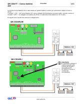
WARNING! The SP01 control card directly supplies the 24V system through output 5-6 therefore the 230V power
supply of the automation must be disconnected.
Connections:
- terminals 1-2 panel input (polarity must be respected)
3 - 4 battery input CHECK POLARITY
9 - 11 command output (to be connected to
the command input e.g. Step-step) that repeats the signal of the first radio channel
and/or P1 wire control (terminals 12-14)
Optional connections:
9 - 10 auxiliary command output (to be connected for example to the “pedestrian opening”) that repeats the signal of the second
radio channel and/or P2 wire control
(terminals 12 13)
12 - 13 - 14 inputs for wire controls
15 - 16 input for off control (see “SP01 Functions”)
17 - 18 input for receiver aerial (see OC2 receiver instructions)
7 - 8 24V output (max 100mA) for one buzzer (and/or one LED) to indicate the state of the
system.
SP01 Functions
Automatic switching off with gate open indicator.
This option optimises the length of time the system is switched on and consequently increases the autonomy of the battery.
Place dip-switch 1 onto ON and connect the “gate open indicator” signal to input 15-16; when the gate is completely closed and
the
indicator is off the SP01 control unit will switch off the power supply. The TL trimmer adjusts the maximum on-time beyond
which the SP01 will switch off in any case.
Switching off with timer
Place dip-switch 1 on OFF and adjust the on time using the TL trimmer.
The time is
recharged using commands P1 and P2 and/or the remote control.
Battery level indicator
The batteries connected to the Sun Power are constantly monitored by the SP01 control unit and their state is indicated by the
LEDS LD1 (green) and LD2 (red). For an acoustic signal connect a buzzer to terminals 7-8
(see "optional connections")
1 beep and flashing green LED = charged batteries (voltage over 25V)
2 beeps and flashing green and red LEDs = batteries being charged (voltage between 21 and 25V)
3 beeps and flashing red LED = flat batteries (voltage below 21V) and system blocked
Indicator of charge from panel
When the output of the SP01 control unit has been activated the green LED not only signals the battery charge level but also
whether the panels are supplying sufficient voltage to charge the battery.
The test can only be carried out when it is sunny (illuminated panels) and is useful to
check the panel connections. Test:
- during the pauses of the battery indicator the green LED (LD1) flashes fast for 1-2 second: system OK
- the green LED does not flash: check panel connections and polarity.
STEUERUNG SP01
ACHTUNG! Die Steuerkarte SP01 speist die 24V-Anlage direkt durch den Ausgang 5 - 6,
somit muss die 230V-Speisung
der Automatisierung abgetrennt bleiben.
Anschlüsse:
- Klemmen 1 2 Eingang Kollektoren (die Polarität einhalten)
3 - 4 Batterieeingang DIE POLARITÄT BEACHTEN
9 - 11 Steuerausgang (an den Steuereingang anzuschließen, z.B. Schrittbetrieb), somit wird das Signal des ersten Funkkanals
und/oder der Kabelsteuerung P1 wiederholt (Klemmen 12 - 14).
Zusätzliche Anschlüsse:
9 - 10 zusätzlicher Steuerausgang (zum Beispiel an den Eingang „Fußgängeröffnung“ anzuschließen); dieser wiederholt das
Signal des zweiten Funkkanals und/oder der Kabelsteuerung P2 (Klemmen 1213)
12 - 13 14 Eingänge für Kabelsteuerungen
15 - 16 Eingang für die Ausschaltsteuerung (siehe „Funktionen SP01“)
17 - 18 Eingang für Empfangsantenne (siehe Anleitungen
Empfänger OC2)
7 - 8 Ausgang 24V (max. 100mA) für einen Summer (und/oder eine Led) zur Anzeige des Anlagenzustands.
Funktionen SP01
Automatisches Abschalten mit Meldeleuchte Tor geöffnet
Diese Option optimiert die Einschaltzeit der Anlage und erhöht somit die Autonomie der Batterien.
Den Dip-Switch 1 auf ON stellen und am Eingang 15-16 das Signal
der „Meldeleuchte Tor geöffnet“ anschließen, wenn das Tor
das Schließen vervollständigt und die Meldeleuchte erlischt, stoppt die Steuerung SP01 die Speisung. Der Trimmer TL regelt
UK
D
12

SP01
12V 7Ah 12V 7Ah
17
OUT 24Vdc
Buzzer
24Vdc
Ant
P1
OUT1
P2
OUT2
PFV
ON TON = Tspia c.a. (max TL)
OFF T
ON = TL
TL (0” - 540”)
10A
In spia c.a. (24V)
1
9
2
10
3
11
4
12
5
13
6
14
7
15
17
8
16
18
14
/