Page is loading ...

SPARK MODERN FIRES
512/612-
BUILT-IN DIRECT VENT GAS FIREPLACE
INSTALLATION-&-OPERATION-MANUAL-
Report-#0361GF006S-
This appliance may be installed in an aftermarket, permanently
located, manufactured home (USA only) or mobile home,
where not prohibited by local codes.
This appliance is only for use with the type of gas indicated on
the rating plate. This appliance is not convertible for use with
other gases, unless a certified kit is used.
Ce manual est disponsible en Francais sur demande.

3
TABLE OF CONTENTS
Important Safety Information 4
Model Descriptions 6
Specifications
7
Clearances 11
Installation Information 14
Venting 16
Final Assembly 20
Lighting & Operation 24
Remote Handset Operation 26
Gas Conversion 33
Maintenance 35
Maintenance Log 36
Replacement Parts List 37
Control Schematic 38
Installation Record 39
Warranty Information 40
WE STRONGLY SUGGEST THAT YOU READ THIS MANUAL THOROUGHLY BEFORE BEGININNG THE
INSTALLATION OF THE DIRECT VENT GAS FIREPLACE. ALTHOUGH THE BASIC REQUIREMENTS FOR
THE INSTALLATION OF ALL DIRECT VENT GAS FIREPLACES ARE SIMILAR, EACH SPECIFIC PRODUCT HAS
ITS OWN UNIQUE SET-UP AND INSTALLATION REQUIREMENTS THAT MUST BE FOLLOWED EXACTLY.
PLAN YOUR INSTALLATION IN ADVANCE BY CAREFULLY RE-VIEWING ALL THE INFORMATION
CONTAINED IN THIS MANUAL.

4
IMPORTANT SAFETY INFORMATION
The installation must conform with local codes or, in the absence of local codes, with the National Fuel
Gas Code, ANSI Z223.1/NFPA 54, or the Natural Gas and Propane Installation Code, CSA B149.1.
A manufactured home (USA only) or mobile home OEM installation must conform with the
Manufactured Home Construction and Safety Standard, Title 24 CFR, Part 3280 or when such a standard
is not applicable, the Standard for Manufactured Home Installations, ANSI/BCSBCS A225.1, or Standard
for Gas Equipped Recreational Vehicles and Mobile Housing, CSA Z240.4.
The appliance and its appliance main gas valve must be disconnected from the gas supply piping
system during any pressure testing of that system at test pressures in excess of 1/2 psi (3.5 kPa).
The appliance must be isolated from the gas supply piping system by closing its equipment shutoff
valve during any pressure testing of the gas supply piping system at test pressures equal to or less than
1/2 psi (3.5 kPa).
The installation must provide for adequate ventilation air to the appliance.
This gas appliance must not be connected to a chimney flue serving a separate solid-fuel burning
appliance.
The appliance, when installed, must be electrically grounded in accordance with local codes, or, in the
absence of local codes, with the National Electrical Code ANSI/NFPA 70, or the Canadian Electrical Code,
CSA C22. 1.
The appliance area must be kept clear and free from combustible materials, gasoline and other
flammable vapors and liquids.
The flow of combustion and ventilation air must not be obstructed. Adequate accessibility clearances
must be maintained for servicing and proper operation of this appliance.
Do not use this appliance if any part has been under water. Immediately call a qualified service
technician to inspect the appliance and to replace any part of the control system and any gas control
which has been under water.
Due to high temperatures, the appliance should be located out of traffic and away from furniture and
draperies.
Children and adults should be alerted to the hazards of high surface temperatures and should stay away to
avoid burns or clothing ignition.
Young children should be carefully supervised when they are in the same room as the appliance. Toddlers,
young children and others may be susceptible to accidental contact burns. A physical barrier is
recommended if there are at-risk individuals in the house. To restrict access to a fireplace or stove, install
an adjustable safety gate to keep toddlers, young children and other at-risk individuals out of the room
and away from hot surfaces.
A barrier designed to reduce the risk of burns from the hot viewing glass is provided with this appliance
and shall be installed for the protection of children and other at-risk individuals.
If the barrier becomes damaged, the barrier shall be replaced with the manufacturer’s barrier for this
appliance.
Clothing or other flammable material should not be placed on or near the appliance.
Any screen or guard removed for servicing an appliance must be replaced prior to operating the appliance.

5
IMPORTANT SAFETY INFORMATION
Installation and repair should be done by a qualified service person. The appliance should be
inspected before use and at least annually by a professional service person. More frequent
cleaning may be required due to excessive lint from carpeting, bedding material, etc. It is
imperative that the control compartments, burners and circulating air passageways of the
appliance be kept clean.
WARNING: Do not operate the appliance with the glass door assembly removed, or if the glass is
cracked or broken. Replacement of the glass should be done by a qualified service person.
WARNING: Use only glass assembly, P/N 48-510 which includes the glass panel, frame and gasket. Do
not use substitute materials. Do not strike or slam the glass front. Do not use abrasive cleaners. Do
not clean when hot.
CAUTION: DO NOT OPERATE WITH BROKEN GLASS
Installation and repair should be done by a qualified service person. The appliance should be inspected
before use and at least annually by a professional service person. More frequent cleaning may be
required due to excessive lint from carpeting, bedding material, etc. It is imperative that the control
compartment, burners and circulating air passageways of the appliance be kept clean.
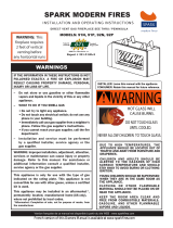
Note:
Periodically conduct a visual check to
ensure the pilot and burner flames are
as shown (right).
Vent Installation Note:
When the first piece of Directvent pipe
is attached to the starter collar of the
fireplace, be sure to inspect both the
inside and outside joints to ensure a
secure fit with no air gaps. Once it is
confirmed there are no gaps, rotate
the pipe clockwise to lock it in place.
Follow the vent manufacture’s
installation instructions during vent
pipe installation.

6
MODEL DESCRIPTIONS
512 VU-THRU
MODEL NO. BI-60-ST
612 VU-THRU
MODEL NO. BI-72-ST

7
SPECIFICATIONS
CERTIFICATION
This appliance has been certified by OMNI-Test Laboratories, Inc. to ANSI Z21.88-2014/CSA 2.33-2014 Vented
Gas Fireplace Heaters and CAN/CGA-2.17-M91 (R2014), Gas-Fired Appliances for Use At High Altitudes.
This SPARK MODERN FIRES Gas Fireplace is approved for installation at elevations up to 2000 feet in the
U.S. and 1370 meters (4500 feet) in Canada without change. If your installation is at an elevation greater
than these, consult with the local authority having jurisdiction for gas product installations to determine
their specific requirements for high altitude installations.
These appliances are approved for installation in the Commonwealth of Massachusetts by the Board of
State Examiners of Plumbers and Gas Fitters.
Sample Rating Label (affixed to control panel within firebox)

8
SPECIFICATIONS
INPUT
512 VU-THRU
612 VU-THRU
Input Rating BTU/Hr.
30,000
34,000
Min. Input BTU/Hr.
21,000
27,000
Orifice Size - DMS
#49
#46
GAS SUPPLY
512 VU-THRU
612 VU-THRU
Manifold Pressure
3.5” w.c. / 0.9kPa
3.5” w.c. / 0.9kPa
Min. Supply Pressure
5.5” w.c. / 1.4kPa
5.5” w.c. / 1.4kPa
Max. Supply Pressure
10.0” w.c. / 2.5kPa
10.0” w.c. / 2.5kPa
INPUT
512 VU-THRU
612 VU-THRU
Input Rating BTU/Hr.
34,000
40,000
Min. Input BTU/Hr.
25,000
28,000
Orifice Size – DMS
#56
#55
GAS SUPPLY
512 VU-THRU
612 VU-THRU
Manifold Pressure
10.0” w.c. / 2.5kPa
10.0” w.c. / 2.5kPa
Min. Supply Pressure
11.0” w.c. / 2.8kPa
11.0” w.c. / 2.8kPa
Max. Supply Pressure
13.0” w.c. / 3.3kPa
13.0” w.c. / 3.3kPa
Efficiency NG/LP
512 VU-THRU
612 VU-THRU
*Typical Installation, Steady State Efficiency - %
69/73.9
72.6/76.4
Steady State Efficiency - %
64.8/70.8
70.4/74.8
Annual Fuel Utilization Efficiency (AFUE) - %
62.8/68.6
68.2/72.5
Canadian p.4 Efficiency - %
64.5/67.7
69.8/72.7
*Your efficiency will increase with the length of the vent run. The typical installation tested is 5ft vertical and 5ft horizontal.
NOTE: The maximum achievable steady state efficiency can vary depending on how the fireplace
is installed and operated.
• It is recommended that the pilot flame be turned off if the appliance will not be in use for an
extended period of time.
• This appliance is equipped for use with the fuel type indicated on the rating plate. Field
conversion is only permitted with a conversion kit supplied by SPARK MODERN FIRES.

9
SPECIFICATIONS
512 VU-THRU
612 VU-THRU
Dimension “A”
29” (737mm)
29” (737mm)
Dimension “B”
73.625” (1,870mm)
87.625” (2,226mm)
Dimension “C”
59.25” (1,505”)
73.25” (1,861mm)
Dimension “D”
12.75” (324mm)
12.75” (324mm)
Dimension “E”
2.70” (69mm)
2.70” (69mm)
Dimension “F”
11.30” (287mm)
11.30” (287mm)
Dimension “G”
7.95” (202mm)
7.95” (202mm)
Dimension “H”
8.125” (206mm)
8.125” (206mm)
*Dimension “J”
3.25” (83mm)
3.25” (83mm)
*Dimension “K”
30.25” (768.5mm)
30.25” (768.5mm)
Dimension “L”
11.50” (292mm)
11.50” (292mm)
Dimension “M”
23.875” (606.5mm)
23.875” (606.5mm)
Dimension “N”
12” (305mm)
12” (305mm)
*The Horizontal and Vertical vent centerline dimensions’ account for the use of a 45-degree elbow.
The gas fireplace is shipped with a 3/8” tube OD (female) connection. The gas supply piping should
have a separate gas shutoff valve and a 1/8” NPT plugged tapping upstream of the valve. The stove
and its main control valve must be disconnected from the gas supply piping system during any
pressure testing of that system at test pressures in excess of 1/2 psi (3.5 kPa). The stove must be
isolated from the gas supply piping system by closing the main control valve during any pressure
testing of the gas supply system at test pressures equal to or greater than 1/2 psi (3.5 kPa). After the
gas supply has been connected, use a commercial gas leak detector or apply a soapy water solution
to all the fittings to check for gas leaks. Never use a flame to test for leaks.

10
CLEARANCES
512 VU-THRU
612 VU-THRU
Sides
4” (102mm)
4” (102mm)
Floor
1/2” (13mm)
1/2” (13mm)
Back
12” (305mm)
12” (305mm)
Front
12” (305mm)
12” (305mm)
Clearance around vent pipe
1.5” (38mm)
1.5” (38mm)
The image above shows a typical installation.
• All framing, finishing, and construction materials that fall within 4” (102mm) of either the sides
or top of the fireplace must be non-combustible and ½” below the unit.
• Any materials that cover the front face or rear face of the fireplace must be non-combustible.
Allow clearance for removal of fireplace trim, screen, and glass.
• The fireplace must be secured to the framing studs using the nailing flanges as shown above.
Use 2 screws or nails per nailing flange to secure the fireplace.
• The sheet metal face of this fireplace must be covered by a non-combustible material, it may
not be left exposed.
• The floor the fireplace immediately rests on must be constructed of non-combustible material
with an R factor of at least .37, with a minimum thickness of ½” (13mm).

11
CLEARANCES
FRAMING BEFORE INSTALLATION
Sometimes it is necessary to frame the location you will be installing the fireplace before the
fireplace is onsite, the above image shows an example of how to frame the wall before the fireplace is
moved into position.
• All framing, finishing, and construction materials that fall within 4” (102mm) of either the sides or
top of the fireplace must be non-combustible. (shown with a dashed line in the image above)
• Note that the vent starter collar sits slightly above the top surface of the fireplace can, there
must be clearance to allow the fireplace with starter collar to slide into place.
• The floor the fireplace immediately rests on must be constructed of non-combustible material
with an R factor of at least .37, with a minimum thickness of ½” (13mm).
• This framing guide is just an example of the many ways in which a SPARK MODERN FIRES
Fireplace can be installed. You may need to customize this framing design to allow for things
such as doors, windows, countertops, structural frame members or local code requirements.
• Dimension “B” for your model can be found on page 8.

12
CLEARANCES
WARNING
Follow these instructions carefully to ensure safe installation.
Failure to follow instructions exactly can create a fire hazard.
• The combustible area above the facing must not protrude more than ¾ (19mm) from the
facing; if it does, it is considered a mantel and must meet the mantel requirements on the
following page.
• When selecting non-combustible materials for use in the installation, take note of the
material’s propensity to absorb and conduct heat. Materials such as metal, stone, and
ceramics may transmit heat more readily than other building materials.
• Only non-combustible materials (i.e. brick, tile, slate, steel, or other man made materials with a
UL fire rating of Zero) may be used in the construction and installation of this fireplace. Any
material must be fastened to surrounding framing. NOT to the face of the fireplace.
ATTENTION:
Before proceeding with your installation, determine if you plan to use either the Power Vent kit (PV-
800HZ) or the Heat Redistribution Kit (HRD-750). Read the manual for these optional components
before proceeding with your installation, as your installation requirements and procedure may
change.

13
INSTALLATION INFORMATION
WARNING
Read all instructions completely and thoroughly before attempting installation. Failure to do so
could result in serious injury, property damage, or loss of life. Operation of improperly installed or
maintained venting system could result in serious injury, property damage, or loss of life.
NOTE:
Any electrical wiring, gas plumbing, or vent installation required by the appliance must be done prior
to final finishing. The unit shall be test burned on high for at least 30 minutes prior to final finishing to
confirm proper operation. Failure to test the appliance before final finishing may require significant
and costly reconstruction
INSTALLATION PRECAUTIONS:
Consult local building codes before beginning the installation. The installer must make sure to select
the proper vent system for installation. Before installing the vent kit, the installer must read this
fireplace manual and vent kit instructions. Only a qualified, licensed, installer/service person shall
install the venting system. The installer must follow the following safety rules:
• Wear gloves and safety glasses for protection.
• Use extreme caution when using ladders or when on rooftops.
• Be aware of electrical wiring locations in walls and ceilings.
The following actions will void the warranty on your fireplace:
• Installation of any damaged venting component.
• Unauthorized modification of the venting system.
• Installation of any component part not manufactured or approved by SPARK MODERN FIRES
Contemporary Fires.
• Installation other than permitted by these instructions.
NOTICE
Failure to follow these instructions will void the warranty.

14
INSTALLATION INFORMATION
State of Massachusetts:
The installation must be completed by a licensed plumber or gas fitter in the Commonwealth of
Massachusetts.
REQUIREMENTS FOR THE COMMONWEALTH OF MASSACHUSETTS
This product must be installed by a licensed plumber or gas fitter when installed within the
Commonwealth of Massachusetts. If this appliance is installed in a dwelling, building or structure
used in whole or in part for residential purposes and the installation includes a horizontal vent
termination that is less than seven (7) feet above the finished grade in the area of the venting,
including but not limited to decks and porches, a hard-wired carbon monoxide detector with an
alarm and battery back-up must be installed on the floor level of the dwelling, building or structure
where the appliance is to be installed.
Additionally, a hard-wired or battery operated carbon monoxide detector with an alarm must be in-
stalled on each additional level of the dwelling, building or structure served by the appliance. It shall
be the responsibility of the property owner to secure the services of qualified licensed professionals
for the installation of hard-wired carbon monoxide detectors.
In the event that the horizontally vented appliance is installed in a crawl space or attic, the hard-
wired carbon monoxide detector with alarm and battery back-up may be installed on the next
adjacent floor level.
In the event that this requirement cannot be met at the time of completion of the installation of the
appliance, the owner shall have a period of thirty (30) days to comply with the requirement. However,
during said thirty (30) day period, a battery operated carbon monoxide detector with alarm must be
installed.
Each carbon monoxide detector as required in accordance with the above provisions must comply
with NFPA 720 and be ANSI/UL 2034 and IAS certified.
In addition, when the vent termination is less than seven (7) feet above finished grade a metal or
plastic identification plate must be permanently mounted to the exterior of the building at a
minimum height of eight (8) feet above grade directly in line with the exhaust vent terminal. The sign
shall read, in print size no less than one-half (1/2) inch in size, “GAS VENT DIRECTLY BELOW. KEEP
CLEAR OF ALL OBSTRUCTIONS”.
A COPY OF THESE INSTRUCTIONS PLUS ALL VENTING INSTRUCTIONS WHICH IN-CLUDE PARTS LISTS,
AND/OR ALL VENTING DESIGN INSTRUCTIONS MUST REMAIN WITH THE STOVE AT THE COMPLETION
OF THE INSTALLATION.
ATTENTION INSTALLERS: Mark below which venting system was used in the installation. These
instructions must remain with the SPARK MODERN FIRES Gas Fireplace Installation & Operation
Manual.
O Simpson DuraVent GS/PRO® O Selkirk Direct-Temp® O Security Secure Vent™
O AmeriVent Direct™ O Metal Fab Direct Vent O ICC Direct Vent

15
VENTING
WARNING
This fireplace must be vented to the outside. The venting system must NEVER be attached to a
chimney serving a separate solid fuel burning appliance. Each gas appliance must use a separate
vent system. Do not use common vent systems.
INSTALLATION PLANNING
The 512 VU-THRU, and 612 VU-THRU use 4x6 Direct-vent pipe.
There are two basic types of direct-vent installation:
• Horizontal Termination
• Vertical Termination
It is important to select the proper length of vent pipe for the type of termination you choose, taking
into consideration wall thicknesses.
FOR HORIZONTAL TERMINATION
Select the amount of vertical rise
desired. All horizontal run of venting
must have ¼” rise for every 12” of
horizontal run.
WARNING
Never run the vent pipe level or downward. This may cause
excessive temperatures which could cause a fire.
FOR VERTICAL TERMINATION
Measure the distance from the Horizontal Vent Center Line (see diagram on page 8). Add the ceiling
thickness, the vertical rise in an attic or second story, and allow for sufficient vent height above the
roofline.
NOTE:
You may use two 45 elbows in place of a 90 elbow. You must follow rise to run ratios when using
45 elbows. The appliance is approved for use with three 90 elbows maximum of a combination of
90 and 45 elbows up to a maximum of 270.
For two-story applications, firestops are required at each floor level. If an offset is needed in the attic,
additional pipe and elbows will be required.
It is very important that the venting system maintain its balance between the combustion air intake and
the flue gas exhaust. Certain limitations apply to vent configurations and must be strictly followed.
INSTALLING A VENT SYSTEM IN AN OUTSIDE CHASE
A chase is a vertical box like structure built to enclose venting that runs along the outside of a building. A
chase is required for such venting.
NOTICE
Treatment of firestops and construction of the
chase may vary from building type to building
type. These instructions are not substitutes for
local building code requirements.
NOTICE
When installing in a chase, you should insulate the chase as you
would the outside walls of your home. This is especially
important in cold climates. Insulation should be considered a
combustible material. Maintain proper clearances to
combustibles.

16
VENTING
Install a Simpson Duravent (Or equivalent) wall thimble, part number 46DVA-WT (not supplied by SPARK
MODERN FIRES), where the pipe passes through a wall to retain any insulation in the wall and to
maintain proper clearances. If the wall being penetrated is constructed of non-combustible material
only (i.e., Masonry block or concrete), the wall thimble is not required; and a hole with zero clearance is
acceptable (6 ⅝” hole).
NOTICE:
Venting terminals shall not be recessed into a wall or siding.

17
VENTING
This SPARK MODERN FIRES Gas Fireplace has been tested and listed for installation with 4” X 6 5/8” M&G
DuraVent GS/Pro®, Selkirk Direct-Temp®, Security Secure Vent™, AmeriVent Direct™, Metal Fab Direct
Vent and ICC EXCELDirect venting components. Although you may use the pipe components (straight
pipe, elbows, etc.) from any of the listed manufacturers, you may only use the vent terminations (caps)
listed in the chart on the following page. For installations where a snorkel is needed, please note that
only three snorkels are approved for use. Please plan your installation accordingly.
For all specific venting installation requirements, follow the installation instructions included by the
venting manufacturer with the venting system components you have chosen.
PLEASE NOTE:
• It is assumed that the installation will include at least one 90° elbow. Up to three additional 90°
elbows (or equivalent 45° elbows) may also be used. The total venting may not exceed 30 feet
of vertical rise and/or 12 feet horizontal run. Refer to the venting charts on pages 16 for specific
details while you plan your installation. Note: The number of elbows impacts the maximum
allowable horizontal vent run.
• There should be a 1 1/2” overlap of the vent and combustion air tubes, when telescopic joints
are used.
• The location of the vent termination must meet the requirements of the current edition of ANSI
Z223.1/NFPA 54, National Fuel Gas Code or CAN B419.1, Natural Gas and Propane Installation
Code and the requirements shown on page 14 of this manual.
APPROVED VENT
TERMINATIONS
M&G DURAVENT
GS/PRO
SELKIRK DIRECT-
TEMP
SECURITY
SECURE VENT
AMP AMERIVENT
DIRECT
METAL FAB
DIRECT VENT
ICC EXCELDIRECT
VERTICAL CAP
46DVAVCH
1604802
SV4CGC
4DVC
4DVT
TM4VT
HORIZONTAL CAP
46DVAHC
46DVAHRCS
46DVAHSC
1604804
SV4GHC
4DVHC
4DHT
TM4HT
TM4DHT
SNORKEL
N/A
1604836
N/A
4D36C
N/A
TMST36
Just as with any other vented device, vertical vent rise creates draft (negative pressure) in the firebox as
the exhaust gases heat up. If this draft becomes excessive, it can affect the performance or appearance
of the fire. The SPARK MODERN FIRES Gas Fireplace includes an integrated air restrictor that can used to
balance the draft in the fireplace to the optimal level for installations where excessive draft might occur.
The SPARK MODERN FIRES Gas Fireplace will ship from the factory with the air restrictor set to the #1
position. If the licensed fireplace installer determines that draft reduction is necessary, loosen the
fastener on the dial and make small adjustments from #1 to #4 until a satisfactory result has been
achieved.
The air restrictor dial is located on the flue side of the firebox when
viewed from the front. To access, remove the lower air screen and side
panels. Once satisfied with the air restrictor adjustment, secure its
position by tightening all hardware.

18
VENTING
SPARK MODERN FIRES flue restrictor kit, part #11317
Some vent configurations may create excess draft within the fireplace. Excess draft can cause
issues such as a rapid, or “nervous” flame picture, undesirable flame color, or pilot lifting which may
prevent the fireplace from staying lit. In these circumstances it may be necessary to install the flue
restrictor kit part #11317 in the venting system. It is permissible to install this restrictor at the vent cap
should the venting system already be installed. Secure the restrictor plate with the included #10 sheet
metal screws.
Vent chart for 512 VU-THRU and 612 VU-THRU.
Power vent runs of up to 110ft with (6) 90 elbows are permitted when using the SPARK MODERN
FIRES power vent kit PV-800HZ. Refer to power vent instructions for additional power vent
installation and operation information.

19
VENTING
Use this worksheet to determine the equivalent horizontal run for use with the vent charts on the next
page. The information contained within this worksheet may also be useful during installation or in the
event that you need technical assistance from SPARK MODERN FIRES.
A. FUEL TYPE O NATURAL GAS O LP GAS (PROPANE)
B. TOTAL VERTICAL VENT RISE (MEASURED FROM HORIZONTAL CENTERLINE OF VENT OPENING ON
THE BACK OF THE FIREPLACE TO THE HORIZONTAL CENTERLINE OF THE VENT CAP (FOR
HORIZONTAL VENT CAPS) OR TO THE FLANGE ON THE CAP (FOR VERTICAL CAPS): _____________
FEET
C. TOTAL HORIZONTAL VENT RUN (MEASURED FROM THE VENT STARTER ON THE FIREPLACE TO THE
FLANGE ON THE CAP (FOR HORIZONTAL CAPS) OR TO THE VERTICAL CENTERLINE OF THE CAP
(FOR VERTICAL CAPS)): _____________ FEET
NOTE: THE VERTICAL VENT RISE AND HORIZONTAL VENT RUN ARE THE OFFSETS IN THE LOCATIONS OF
VENT CAP RELATIVE TO THE VENT OPENING ON THE FIREPLACE. VENT PIPE THAT RUNS AT 45° HAVE
BOTH A VERTICAL RISE AND HORIZONTAL RUN. SNORKEL CAPS HAVE BUILT-IN VERTICAL RISE THAT
MUST BE COUNTED.
D. TOTAL NUMBER OF 90° ELBOWS: _______ NOTE: SNORKELS COUNT AS 2- 90° ELBOWS
E. TOTAL NUMBER OF 45° ELBOWS: _______
HORIZONTAL VENT RUN EQUIVALENT CALCULATOR
C. Total horizontal vent run (actual): __________
D. 90 Elbows needed: __________
E. 45 Elbows needed: __________
F. Total 90 Elbows equivalent: D+(Ex½) =_________
G. 90 Elbows in excess or 2: F-2 =_________
H. Additional horiz. feet (equivalent): Gx3 =_________
I. Horizontal vent run (equivalent): C+H =_________
TERMINATION (CAP) TYPE: O HORIZONTAL O VERTICAL O SNORKEL
VENT BRAND:
O Simpson DuraVent GS/PRO® O Selkirk Direct-Temp® O Security Secure Vent™
O AmeriVent Direct™ O Metal Fab Direct Vent O ICC Direct Vent
VENT CAP MODEL NO: ____________ NOTE: SEE APPROVED VENT CAPS ON THE PREVIOUS PAGE.
WAS THE FIREPLACE INSTALLED WITH A SPARK MODERN FIRES POWER VENT? (CIRCLE ONE) Y N

20
FINAL ASSEMBLY
SCREEN REMOVAL:
1. Lift up on the lower air panel to remove it
from the fireplace opening.
2. Remove the left and right side panels by
lifting up and toward you.
3. The fireplace screen is held in place by 3
self-tensioning latches along its top edge
(4 latches on the 612). Release these
latches to remove the screen.
4. Allow the screen to rest in the fireplace
opening, confirm that the latches are in
their “home” position.
5. Lift the screen up so that the bottom of
the screen clears the bottom of the
fireplace opening.
6. Angle the screen toward you from the
bottom to remove.
To reinstall the screen, reverse these steps.
Remember to confirm the latches are in their
“home” position any time you are installing or
removing the screen.
NOTICE
If this screen is removed for servicing this
appliance it must be replaced prior to
operating the appliance.

21
FINAL ASSEMBLY
FINAL ASSEMBLYGLASS REMOVAL:
1. With the screen removed, loosen the ¼-
20 bolts along the top edge of the glass
frame using a 7/16 socket.
2. Confirm that the Screen latches are in
their “home” position. (see image
3. Lift the glass frame assembly up so that
the bottom of the glass frame assembly
clears the bottom of the fireplace
opening.
NOTICE
Do not attempt to operate the fireplace
without the screen or glass frame assembly in
place. Doing so could lead to injury, property
damage, or loss of life.
4. Angle the glass assembly toward you from
the bottom to remove.
Refer to the next page for instructions on burner
media placement.
GLASS INSTALLATION:
1. Insert the glass frame assembly into the
fireplace by angling the top of the glass in
and up into the fireplace.
2. Lift the glass frame assembly up so that the
bottom of the glass frame assembly clears
the bottom of the fireplace opening.
3. Slide the glass frame into the glass frame
retainer along the bottom of the firebox
opening.
4. Install the ¼-20 bolts along the top edge of
the glass frame assembly and tighten using
a 7/16 socket.
/