Page is loading ...

100
100%
Duty
Cycle
PIP
H/F
LV
Start
Max
Input
125PSI
Op Pres
60-75
PSI
Max
Flow
400 scfh
60
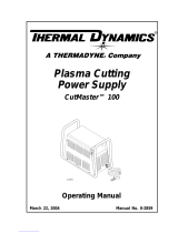
PLASMA CUTTING TORCH
Rev. AA.02 Date: July 23, 2007 Manual # 0-2962
Operating Features:
Instruction Manual
SL60
SL100
Model SL60, SL100 Hand
Torch
Model SL100 Machine Torch

WE APPRECIATE YOUR BUSINESS!
Congratulations on your new Thermal Dynamics product. We are proud
to have you as our customer and will strive to provide you with the
best service and reliability in the industry. This product is backed by
our extensive warranty and world-wide service network. To locate
your nearest distributor or service agency call 1-800-426-1888, or
visit us on the web at www.thermal-dynamics.com.
This Operating Manual has been designed to instruct you on the cor-
rect use and operation of your Thermal Dynamics product. Your sat-
isfaction with this product and its safe operation is our ultimate con-
cern. Therefore please take the time to read the entire manual,
especially the Safety Precautions. They will help you to avoid poten-
tial hazards that may exist when working with this product.
YOU ARE IN GOOD COMPANY!
The Brand of Choice for Contractors and Fabricators Worldwide.
Thermal Dynamics is a Global Brand of manual and automation Plasma
Cutting Products for Thermadyne Industries Inc.
We distinguish ourselves from our competition through market-lead-
ing, dependable products that have stood the test of time. We pride
ourselves on technical innovation, competitive prices, excellent de-
livery, superior customer service and technical support, together with
excellence in sales and marketing expertise.
Above all, we are committed to developing technologically advanced
products to achieve a safer working environment within the welding
industry.

WARNINGS
Read and understand this entire Manual and your employer’s safety practices before
installing, operating, or servicing the equipment.
While the information contained in this Manual represents the Manufacturer's best judge-
ment, the Manufacturer assumes no liability for its use.
Plasma Cutting Torch
Model SL60 and SL100 Hand Torch
Model SL100 Machine Torch
Instruction Manual Number 0-2962
Protected under U.S. Patent Number 6,163,008. Other patents may apply.
Published by:
Thermal Dynamics Corporation
82 Benning Street
West Lebanon, New Hampshire, USA 03784
(603) 298-5711
www.thermal-dynamics.com
Copyright 2003, 2004, 2005, 2006, 2007 by
Thermal Dynamics Corporation
All rights reserved.
Reproduction of this work, in whole or in part, without written permission of the
publisher is prohibited.
The publisher does not assume and hereby disclaims any liability to any party for
any loss or damage caused by any error or omission in this Manual, whether such
error results from negligence, accident, or any other cause.
Printed in the United States of America
Publication Date: September 29, 2005
Record the following information for Warranty purposes:
Where Purchased: ___________________________________
Purchase Date: ___________________________________
Power Supply Serial #: ___________________________________
Torch Serial #: ___________________________________


Manual 0-2962 1-1 GENERAL INFORMATION
SECTION 1:
GENERAL INFORMATION
1.01 Notes, Cautions and Warnings
Throughout this manual, notes, cautions, and warnings
are used to highlight important information. These high-
lights are categorized as follows:
NOTE
An operation, procedure, or background informa-
tion which requires additional emphasis or is help-
ful in efficient operation of the system.
CAUTION
A procedure which, if not properly followed, may
cause damage to the equipment.
WARNING
A procedure which, if not properly followed, may
cause injury to the operator or others in the oper-
ating area.
1.02 Important Safety Precautions
WARNINGS
OPERATION AND MAINTENANCE OF
PLASMA ARC EQUIPMENT CAN BE DAN-
GEROUS AND HAZARDOUS TO YOUR
HEALTH.
Plasma arc cutting produces intense electric and
magnetic emissions that may interfere with the
proper function of cardiac pacemakers, hearing aids,
or other electronic health equipment. Persons who
work near plasma arc cutting applications should
consult their medical health professional and the
manufacturer of the health equipment to determine
whether a hazard exists.
To prevent possible injury, read, understand and
follow all warnings, safety precautions and instruc-
tions before using the equipment. Call 1-603-298-
5711 or your local distributor if you have any ques-
tions.
GASES AND FUMES
Gases and fumes produced during the plasma cutting
process can be dangerous and hazardous to your health.
• Keep all fumes and gases from the breathing area.
Keep your head out of the welding fume plume.
• Use an air-supplied respirator if ventilation is not
adequate to remove all fumes and gases.
• The kinds of fumes and gases from the plasma arc
depend on the kind of metal being used, coatings
on the metal, and the different processes. You must
be very careful when cutting or welding any met-
als which may contain one or more of the follow-
ing:
Antimony Chromium Mercury
Arsenic Cobalt Nickel
Barium Copper Selenium
Beryllium Lead Silver
Cadmium Manganese Vanadium
• Always read the Material Safety Data Sheets
(MSDS) that should be supplied with the material
you are using. These MSDSs will give you the in-
formation regarding the kind and amount of fumes
and gases that may be dangerous to your health.
• For information on how to test for fumes and gases
in your workplace, refer to item 1 in Subsection 1.03,
Publications in this manual.
• Use special equipment, such as water or down draft
cutting tables, to capture fumes and gases.
• Do not use the plasma torch in an area where com-
bustible or explosive gases or materials are located.
• Phosgene, a toxic gas, is generated from the vapors
of chlorinated solvents and cleansers. Remove all
sources of these vapors.
• This product, when used for welding or cutting, pro-
duces fumes or gases which contain chemicals
known to the State of California to cause birth de-
fects and, in some cases, cancer. (California Health
& Safety Code Sec. 25249.5 et seq.)
ELECTRIC SHOCK
Electric Shock can injure or kill. The plasma arc process
uses and produces high voltage electrical energy. This
electric energy can cause severe or fatal shock to the op-
erator or others in the workplace.
• Never touch any parts that are electrically “live” or
“hot.”

GENERAL INFORMATION 1-2 Manual 0-2962
• Wear dry gloves and clothing. Insulate yourself
from the work piece or other parts of the welding
circuit.
• Repair or replace all worn or damaged parts.
• Extra care must be taken when the workplace is
moist or damp.
• Install and maintain equipment according to NEC
code, refer to item 9 in Subsection 1.03, Publications.
• Disconnect power source before performing any ser-
vice or repairs.
• Read and follow all the instructions in the Operat-
ing Manual.
FIRE AND EXPLOSION
Fire and explosion can be caused by hot slag, sparks, or
the plasma arc.
• Be sure there is no combustible or flammable mate-
rial in the workplace. Any material that cannot be
removed must be protected.
• Ventilate all flammable or explosive vapors from
the workplace.
• Do not cut or weld on containers that may have held
combustibles.
• Provide a fire watch when working in an area where
fire hazards may exist.
• Hydrogen gas may be formed and trapped under
aluminum workpieces when they are cut underwa-
ter or while using a water table. DO NOT cut alu-
minum alloys underwater or on a water table un-
less the hydrogen gas can be eliminated or
dissipated. Trapped hydrogen gas that is ignited
will cause an explosion.
NOISE
Noise can cause permanent hearing loss. Plasma arc pro-
cesses can cause noise levels to exceed safe limits. You
must protect your ears from loud noise to prevent per-
manent loss of hearing.
• To protect your hearing from loud noise, wear pro-
tective ear plugs and/or ear muffs. Protect others
in the workplace.
• Noise levels should be measured to be sure the deci-
bels (sound) do not exceed safe levels.
• For information on how to test for noise, see item 1
in Subsection 1.03, Publications, in this manual.
PLASMA ARC RAYS
Plasma Arc Rays can injure your eyes and burn your skin.
The plasma arc process produces very bright ultra violet
and infra red light. These arc rays will damage your eyes
and burn your skin if you are not properly protected.
• To protect your eyes, always wear a welding hel-
met or shield. Also always wear safety glasses with
side shields, goggles or other protective eye wear.
• Wear welding gloves and suitable clothing to pro-
tect your skin from the arc rays and sparks.
• Keep helmet and safety glasses in good condition.
Replace lenses when cracked, chipped or dirty.
• Protect others in the work area from the arc rays.
Use protective booths, screens or shields.
• Use the shade of lens as suggested in the following
per ANSI/ASC Z49.1:
Minimum Protective Suggested
Arc Current Shade No. Shade No.
Less Than 300* 8 9
300 - 400* 9 12
400 - 800* 10 14
* These values apply where the actual arc is clearly
seen. Experience has shown that lighter filters may
be used when the arc is hidden by the workpiece.
1.03 Publications
Refer to the following standards or their latest revisions
for more information:
1. OSHA, SAFETY AND HEALTH STANDARDS, 29CFR
1910, obtainable from the Superintendent of Documents,
U.S. Government Printing Office, Washington, D.C.
20402
2. ANSI Standard Z49.1, SAFETY IN WELDING AND
CUTTING, obtainable from the American Welding So-
ciety, 550 N.W. LeJeune Rd, Miami, FL 33126
3. NIOSH, SAFETY AND HEALTH IN ARC WELDING
AND GAS WELDING AND CUTTING, obtainable from
the Superintendent of Documents, U.S. Government
Printing Office, Washington, D.C. 20402
4. ANSI Standard Z87.1, SAFE PRACTICES FOR OCCU-
PATION AND EDUCATIONAL EYE AND FACE PRO-
TECTION, obtainable from American National Stan-
dards Institute, 1430 Broadway, New York, NY 10018
5. ANSI Standard Z41.1, STANDARD FOR MEN’S
SAFETY-TOE FOOTWEAR, obtainable from the Ameri-
can National Standards Institute, 1430 Broadway, New
York, NY 10018

Manual 0-2962 1-3 GENERAL INFORMATION
6. ANSI Standard Z49.2, FIRE PREVENTION IN THE USE
OF CUTTING AND WELDING PROCESSES, obtain-
able from American National Standards Institute, 1430
Broadway, New York, NY 10018
7. AWS Standard A6.0, WELDING AND CUTTING
CONTAINERS WHICH HAVE HELD COMBUS-
TIBLES, obtainable from American Welding Society,
550 N.W. LeJeune Rd, Miami, FL 33126
8. NFPA Standard 51, OXYGEN-FUEL GAS SYSTEMS
FOR WELDING, CUTTING AND ALLIED PRO-
CESSES, obtainable from the National Fire Protection
Association, Batterymarch Park, Quincy, MA 02269
9. NFPA Standard 70, NATIONAL ELECTRICAL CODE,
obtainable from the National Fire Protection Associa-
tion, Batterymarch Park, Quincy, MA 02269
10. NFPA Standard 51B, CUTTING AND WELDING PRO-
CESSES, obtainable from the National Fire Protection
Association, Batterymarch Park, Quincy, MA 02269
11. CGA Pamphlet P-1, SAFE HANDLING OF COM-
PRESSED GASES IN CYLINDERS, obtainable from the
Compressed Gas Association, 1235 Jefferson Davis
Highway, Suite 501, Arlington, VA 22202
12. CSA Standard W117.2, CODE FOR SAFETY IN WELD-
ING AND CUTTING, obtainable from the Canadian
Standards Association, Standards Sales, 178 Rexdale
Boulevard, Rexdale, Ontario, Canada M9W 1R3
13. NWSA booklet, WELDING SAFETY BIBLIOGRAPHY
obtainable from the National Welding Supply Associa-
tion, 1900 Arch Street, Philadelphia, PA 19103
14. American Welding Society Standard AWSF4.1, RECOM-
MENDED SAFE PRACTICES FOR THE PREPARA-
TION FOR WELDING AND CUTTING OF CONTAIN-
ERS AND PIPING THAT HAVE HELD HAZARDOUS
SUBSTANCES, obtainable from the American Welding
Society, 550 N.W. LeJeune Rd, Miami, FL 33126
15. ANSI Standard Z88.2, PRACTICE FOR RESPIRATORY
PROTECTION, obtainable from American National
Standards Institute, 1430 Broadway, New York, NY
10018

GENERAL INFORMATION 1-4 Manual 0-2962
1.04 Declaration of Conformity
Manufacturer: Thermal Dynamics Corporation
Address: 82 Benning Street
West Lebanon, New Hampshire 03784
USA
The equipment described in this manual conforms to all applicable aspects and regulations of the ‘Low Voltage Directive’
(European Council Directive 73/23/EEC as amended by Council Directive 93/68/EEC) and to the National legislation for
the enforcement of this Directive.
Serial numbers are unique with each individual piece of equipment and details description, parts used to manufacture a unit
and date of manufacture.
National Standard and Technical Specifications
The product is designed and manufactured to a number of standards and technical requirements. Among them are:
* CSA (Canadian Standards Association) standard C22.2 number 60 for Arc welding equipment.
* UL (Underwriters Laboratory) rating 94VO flammability testing for all printed-circuit boards used.
* ISO/IEC 60974-1 (BS 638-PT10) (EN 60 974-1) (EN50192) (EN50078) applicable to plasma cutting equipment and associ-
ated accessories.
* Extensive product design verification is conducted at the manufacturing facility as part of the routine design and manufac-
turing process. This is to ensure the product is safe, when used according to instructions in this manual and related
industry standards, and performs as specified. Rigorous testing is incorporated into the manufacturing process to ensure
the manufactured product meets or exceeds all design specifications.
Thermal Dynamics has been manufacturing products for more than 30 years, and will continue to achieve excellence in our
area of manufacture.
Manufacturers responsible representative: Steve Ward
Operations Director
Thermadyne Europe
Europa Building
Chorley N Industrial Park
Chorley, Lancashire,
England PR6 7BX

Manual 0-2962 1-5 GENERAL INFORMATION
1.05 Statement of Warranty
LIMITED WARRANTY: Thermal Dynamics
®
Corporation (hereinafter “Thermal”) warrants that its products will be free of defects in
workmanship or material. Should any failure to conform to this warranty appear within the time period applicable to the Thermal
products as stated below, Thermal shall, upon notification thereof and substantiation that the product has been stored, installed, operated,
and maintained in accordance with Thermal’s specifications, instructions, recommendations and recognized standard industry practice,
and not subject to misuse, repair, neglect, alteration, or accident, correct such defects by suitable repair or replacement, at Thermal’s sole
option, of any components or parts of the product determined by Thermal to be defective.
THIS WARRANTY IS EXCLUSIVE AND IS IN LIEU OF ANY WARRANTY OF MERCHANTABILITY OR FITNESS FOR A
PARTICULAR PURPOSE.
LIMITATION OF LIABILITY: Thermal shall not under any circumstances be liable for special or consequential damages, such as, but
not limited to, damage or loss of purchased or replacement goods, or claims of customers of distributor (hereinafter “Purchaser”) for
service interruption. The remedies of the Purchaser set forth herein are exclusive and the liability of Thermal with respect to any
contract, or anything done in connection therewith such as the performance or breach thereof, or from the manufacture, sale, delivery,
resale, or use of any goods covered by or furnished by Thermal whether arising out of contract, negligence, strict tort, or under any
warranty, or otherwise, shall not, except as expressly provided herein, exceed the price of the goods upon which such liability is based.
THIS WARRANTY BECOMES INVALID IF REPLACEMENT PARTS OR ACCESSORIES ARE USED WHICH MAY IMPAIR THE
SAFETY OR PERFORMANCE OF ANY THERMAL PRODUCT.
THIS WARRANTY IS INVALID IF THE PRODUCT IS SOLD BY NON-AUTHORIZED PERSONS.
The limited warranty periods for Thermal products shall be as follows (with the exception of XL Plus Series, CutMaster Series , Cougar
and DRAG-GUN): A maximum of three (3) years from date of sale to an authorized distributor and a maximum of two (2) years from
date of sale by such distributor to the Purchaser, and with the further limitations on such two (2) year period (see chart below).
The limited warranty period for XL Plus Series and CutMaster Series shall be as follows: A maximum of four (4) years from date
of sale to an authorized distributor and a maximum of three (3) years from date of sale by such distributor to the Purchaser, and
with the further limitations on such three (3) year period (see chart below).
The limited warranty period for Cougar and DRAG-GUN shall be as follows: A maximum of two (2) years from date of sale to an
authorized distributor and a maximum of one (1) year from date of sale by such distributor to the Purchaser, and with the further
limitations on such two (2) year period (see chart below).
Parts
XL Plus & Parts Parts
PAK Units, Power Supplies CutMaster Series Cougar/Drag-Gun All Others Labor
Main Power Magnetics 3 Years 1 Year 2 Years 1 Year
Original Main Power Rectifier 3 Years 1 Year 2 Years 1 Year
Control PC Board 3 Years 1 Year 2 Years 1 Year
All Other Circuits And Components Including, 1 Year 1 Year 1 Year 1 Year
But Not Limited To, Starting Circuit,
Contactors, Relays, Solenoids, Pumps,
Power Switching Semi-Conductors
Consoles, Control Equipment, Heat 1 Year 1 Year 1 Year
Exchanges, And Accessory Equipment
Torch And Leads
Maximizer 300 Torch 1 Year 1 Year
SureLok Torches 1 Year 1 Year 1 Year
All Other Torches 180 Days 180 Days 180 Days 180 Days
Repair/Replacement Parts 90 Days 90 Days 90 Days None
Warranty repairs or replacement claims under this limited warranty must be submitted by an authorized Thermal Dynamics® repair
facility within thirty (30) days of the repair. No transportation costs of any kind will be paid under this warranty. Transportation
charges to send products to an authorized warranty repair facility shall be the responsibility of the customer. All returned goods shall
be at the customer’s risk and expense. This warranty supersedes all previous Thermal warranties.
Effective August 6, 2001

GENERAL INFORMATION 1-6 Manual 0-2962

Manual 0-2962 2-1 INTRODUCTION
SECTION 2:
INTRODUCTION
2.01 Scope of Manual
This manual contains descriptions, operating instructions
and maintenance procedures for the 1Torch Models SL60
and SL100 Plasma Cutting Torches. Service of this equip-
ment is restricted to properly trained personnel; unquali-
fied personnel are strictly cautioned against attempting
repairs or adjustments not covered in this manual, at the
risk of voiding the Warranty.
Read this manual thoroughly. A complete understanding
of the characteristics and capabilities of this equipment
will assure the dependable operation for which it was
designed.
2.02 General Description
Plasma torches are similar in design to the automotive
spark plug. They consist of negative and positive sections
separated by a center insulator. Inside the torch, the pilot
arc starts in the gap between the negatively charged elec-
trode and the positively charged tip. Once the pilot arc
has ionized the plasma gas, the superheated column of
gas flows through the small orifice in the torch tip, which
is focused on the metal to be cut.
A single torch lead provides gas from a single source to be
used as both the plasma and secondary gas. The air flow
is divided inside the torch head. Single - gas operation
provides a smaller sized torch and inexpensive operation.
NOTE
Refer to Section 2.05, Introduction To Plasma, for a
more detailed description of plasma torch opera-
tion.
Refer to the Appendix Pages for additional specifi-
cations as related to the Power Supply used.
2.03 Specifications
A. Torch Configurations
1. Hand Torch, Models SL60 and SL100
The hand torch head is at 75° to the torch handle.
The hand torches include a torch handle and torch
trigger assembly.
9.5" (241 mm)
3.75"
(95 mm)
1.17" (29 mm)
Art # A-03322
2. Machine Torch, Model SL100
The standard machine torch has a positioning tube
with rack & pinch block assembly.
Art # A-02998
1.75" /
44.5 mm
1.375" / 35 mm
15.875" / 403 mm
0.625" /
16 mm
4.95" / 126 mm
1.175" / 30 mm
9.285" / 236 mm
B. Torch Leads Lengths
Hand Torches are available as follows:
• 20 ft / 6.1 m, with O2B or ATC connectors
• 50 ft / 15.2 m, with O2B or ATC connectors
Machine Torches are available as follows:
• 5 foot / 1.5 m, with ATC connectors
• 10 foot / 3.05 m, with ATC connectors
• 25 foot / 7.6 m, with O2B or ATC connectors
• 50 foot / 15.2 m, with O2B or ATC connectors
C. Torch Parts
Starter Cartridge, Electrode, Tip, Shield Cup
D. Parts - In - Place (PIP)
Torch Head has built - in switch
12 vdc circuit rating

INTRODUCTION 2-2 Manual 0-2962
E. Type Cooling
Combination of ambient air and gas stream through
torch.
F. Torch Ratings
Ambient
Tem
p
erature
104° F
40° C
Duty Cycle
100% @ 60 Amps @ 400 scfh
Maximum Current
60 Amps
Voltage (V
peak
)
500V
Arc Striking Voltage
7kV
SL60 Torch Ratin
g
s
Ambient
Tem
p
erature
104° F
40° C
Duty Cycle
100% @ 100 Amps @ 400 scfh
Maximum Current
100 Amps
Voltage (V
peak
)
500V
Arc Striking Voltage
7kV
SL100 Torch Ratin
g
s
G. Current Ratings
SL60 Torch & Leads
Up to 60 Amps, DC,
Straight Polarity
SL100 Torch & Leads
Up to 100 Amps, DC,
Straight Polarity
Current Rating
s
!
WARNING
Maximum current is 60 Amps for SL60 Torches, or
100 Amps for SL100 Torches. Operation of this
torch at higher outputs may damage the torch, the
leads, the components, or the Power Supply. DO
NOT operate the SL60 torch at more than 60 Amps,
or the SL100 at more than 100 Amps.
NOTE
Power Supply characteristics will determine mate-
rial thickness range.
H. Gas Requirements
Gas (Plasma and Secondary) Compressed Air
Operating Pressure
Refer to NOTE
60 - 75 psi
4.1 - 5.2 bar
Maximum Input Pressure
125 psi / 8.6
bar
Gas Flow (Cutting and Gouging)
300 - 500 scfh
142 - 235 lpm
SL60 and SL100 Torch Gas Specification
s
!
WARNING
This torch is not to be used with oxygen (O
2
).
NOTE
Operating pressure varies with torch model, oper-
ating amperage, and torch leads length. Refer to
gas pressure settings charts for each model.
I. Direct Contact Hazard
For exposed tip the recommended standoff is 3/16
inches / 4.7 mm.
J. Plasma Power Supply Used With
• CutMaster 50
• CutMaster 51
• CutMaster 75
• CutMaster 81
• CutMaster 100
• CutMaster 101
• CutMaster 151
• PakMaster 50XL Plus
• PakMaster 75XL Plus
• PakMaster 100XL Plus
NOTE
Refer to the Appendix Pages for additional speci-
fications as related to the Power Supply used.

Manual 0-2962 2-3 INTRODUCTION
2.04 Options And Accessories
These items can adapt a standard system to a particular
application or further enhance performance (refer to Sec-
tion 6 for ordering information).
• Spare Parts Kits - Various kits containing replace-
ment consumable torch parts.
• Deluxe Cutting Guide Kit - Easy add - on attach-
ments for precise straight line, circle cutting, and
beveling. Includes carrying case.
• Trigger Guard Kits (for hand torches) - These offer
additional protection from accidental activation of
the torch switch.
• 1 - 3/8" Mounting Tube (for machine torches)
• Pinion Assembly (for machine torches)
• Computer Control (CNC) Cable 25 Ft / 7.6 m or
50 Ft / 15.2 m (for machine torches)
• Remote Pendant Control Assembly - for machine
torch applications. Hand Pendant Control has
20 ft. (6.1 m) cable which provides ON & OFF sig-
nals to the Power Supply.
• Extension Cable for Hand Pendant Control - 25 ft /
7.6 m cable which can be added to the Hand Pen-
dant Control cable to provide a total control cable
length of 50 ft / 15.2 m.
• Leads Extensions for torches with ATC connectors
• Leather Leads Covers
2.05 Introduction to Plasma
A. Plasma Gas Flow
Plasma is a gas which has been heated to an extremely
high temperature and ionized so that it becomes elec-
trically conductive. The plasma arc cutting and goug-
ing processes use this plasma to transfer an electrical
arc to the workpiece. The metal to be cut or removed is
melted by the heat of the arc and then blown away.
While the goal of plasma arc cutting is separation of
the material, plasma arc gouging is used to remove
metals to a controlled depth and width.
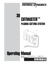
In a Plasma Cutting Torch a cool gas enters Zone B,
where a pilot arc between the electrode and the torch
tip heats and ionizes the gas. The main cutting arc
then transfers to the workpiece through the column of
plasma gas in Zone C.
A-00002
Workpiece
Power
Supply
+
_
C
B
A
Typical Torch Head Detail
By forcing the plasma gas and electric arc through a
small orifice, the torch delivers a high concentration
of heat to a small area. The stiff, constricted plasma
arc is shown in Zone C. Direct current (DC) straight
polarity is used for plasma cutting, as shown in the
illustration.
Zone A channels a secondary gas that cools the torch.
This gas also assists the high velocity plasma gas in blow-
ing the molten metal out of the cut allowing for a fast, slag
- free cut.

INTRODUCTION 2-4 Manual 0-2962
B. Gas Distribution
The single gas used is internally split into plasma and sec-
ondary gases.
The plasma gas flows into the torch through the negative
lead, through the starter cartridge, around the electrode,
and out through the tip orifice.
The secondary gas flows down around the outside of the
torch starter cartridge, and out between the tip and shield
cup around the plasma arc.
C. Pilot Arc
When the torch is started a pilot arc is established be-
tween the electrode and cutting tip. This pilot arc creates
a path for the main arc to transfer to the work.
D. Capacitive Discharge
Because direct current (DC) alone is not sufficient to strike
and maintain the pilot arc, capacitive discharge is also used.
The high voltage jumps between the tip and electrode with
the DC following.
NOTE
Not all power supplies have this feature.
E. Main Cutting Arc
DC power is also used for the main cutting arc. The
negative output is connected to the torch electrode
through the torch lead. The positive output is con-
nected to the workpiece via the work cable and to the
torch through a pilot wire.
F. Parts - In - Place (PIP)
The torch includes a 'Parts - In - Place' (PIP) circuit.
When the shield cup is properly installed, it closes a
switch. The torch will not operate if this switch is
open.
A-02997
Torch Trigger
PIP Switch
Shield Cup
To Control
Cable Wiring
Torch Switch
Parts - In - Place Circuit Diagram for Hand Torch
A-03504
PIP Switch
Shield Cup
To Control
Cable Wiring
Parts - In - Place Circuit Diagram for Machine
Torch
/