CONNECTOR HOOKUP
Pressure
regulator
Gas Flow into Range Gas Flow into Range
Flex
connector
(6 ft. max.)
Adapter
Installer: Inform the consumer of the location of the gas shut-off valve.
1/2” or 3/4”
Gas pipe
Adapter
Gas
shut-off
valve
Pressure
regulator
Elbow
Elbow
Nipple
Union
Nipple
Gas
shut-off
valve
1/2” or 3/4”
Gas pipe
Flexible
Option
Rigid Pipe
Option
6
GAS SUPPLY
WARNING Fire Hazard: Do not use a
flame to check for gas leaks.
WARNING Explosion Hazard: Do not
exceed 25 ft-lbs of torque when making gas
line connections. Overtightening may crack
the pressure regulator resulting in fire or
explosion hazard.
Gas Pressure Regulator
You must use the gas pressure regulator supplied
with this range. For proper operations the inlet
pressure to the regulator should be as follows:
Natural Gas:
Minimum pressure: 6” of Water Column
Maximum pressure: 13” of Water Column
LP Gas:
Minimum pressure: 11” of Water Column
Maximum pressure: 13” of Water Column
If you are not sure about the inlet pressure
contact local gas supplier.
Shut off the main gas supply valve before
disconnecting the old range and leave it off
until the new hook-up has been completed.
Don’t forget to relight the pilot on other gas
appliances when you turn the gas back on.
Because hard piping restricts movement of
the range, the use of a CSA International-
certified flexible metal appliance connector is
recommended unless local codes require a hard-
piped connection.
If the hard piping method is used, you must
carefully align the pipe; the range cannot be
moved after the connection is made.
To prevent gas leaks, put pipe joint compound on,
or wrap pipe thread tape with Teflon* around, all
male (external) pipe threads.
A. Install a manual shut-off valve in the gas line
in an easily accessed location outside of the
range. Make sure everyone operating the
range knows where and how to shut off the
gas supply to the range.
B. Install male 1/2” flare union adapter to the 1/2”
NPT internal thread at inlet of regulator. Use a
backup wrench on the regulator fitting to avoid
damage.
C. Install male 1/2” or 3/4” flare union adapter to
the NPT internal thread of the manual shut-off
valve, taking care to back-up the shut-off valve
to keep it from turning.
D. Connect flexible metal appliance connector
to the adapter on the range. Position range to
permit connection at the shut-off valve.
E. When all connections have been made, make
sure all range controls are in the off position
and turn on the main gas supply valve.
Use a liquid leak detector at all joints and
connections to check for leaks in the system.
When using pressures greater than 1/2 psig
to pressure test the gas supply system of the
residence, disconnect the range and individual
shut-off valve from the gas supply piping. When
using pressures of 1/2 psig or less to pressure
test the gas supply system, simply isolate the
range from the gas supply system by closing the
individual shut-off valve.
When checking for proper operation of the
regulator, the inlet pressure must be at least 1”
greater than the operating (manifold) pressure as
given on rating label of product.
*Teflon: Registered trademark of DuPont
6
GAS SUPPLY (CONT)
8
CHECK SURFACE BURNERS
Push and turn knob to LITE position. You will hear
a clicking sound indicating proper operation of
the spark module. Once the air has been purged
from the supply lines, burners should light within
4 seconds. After burner lights, rotate knob out of
the LITE position. Try each burner in succession
until all burners have been checked.
Quality of Flames
The flame quality of the burners needs to be
determined visually.
If burner flames look like (A), call for service.
Normal burner flames should look like (B) or (C),
depending on the type of gas you use
With LP gas, some yellow tipping on outer cones
is normal.
WHEN ALL HOOKUPS ARE
COMPLETED
Make sure all controls are left in the off position.
Make sure the flow of combustion and ventilation
air to the range is unobstructed.
Check that all packing materials and tape have
been removed. This will include tape on metal
panel under control knobs (if applicable), adhesive
tape, wire ties, cardboard and protective plastic.
Failure to remove these materials could result in
damage to the appliance once the appliance has
been turned on and surfaces have heated.
&6RIWEOXHIODPHV³
Normal for natural gas
(B) Yellow tips on
RXWHUFRQHV³
Normal for LP gas
$<HOORZIODPHV³
Call for service
9
INSTALL AND CHECK
ANTI-TIP DEVICE
WARNING
Never completely remove the
leveling leg as the range will not be secured to
the anti-tip device properly.
Follow instructions supplied with ANTI-TIP bracket
Anti-Tip Bracket
Kit Included
11
FINAL INSTALLATION CHECKLIST
&KHFNWRPDNHVXUHWKHFLUFXLWEUHDNHULVFORVHG5(6(7RUWKHFLUFXLWIXVHVDUHUHSODFHG
%HVXUHSRZHUWRWKHEXLOGLQJLVLQVHUYLFH
&KHFNWKDWDOOSDFNLQJPDWHULDOVDQGWDSHKDYHEHHQUHPRYHG7KLVLQFOXGHVDOODGKHVLYHWDSHZLUH
ties, cardboard and protective plastic. Failure to remove these materials could result in damage to the
appliance once the appliance has been turned on and surfaces have heated.
&KHFNWKDWWKHGRRUDQGGUDZHUDUHSDUDOOHOWRHDFKRWKHUDQGWKDWERWKRSHUDWHVPRRWKO\,IWKH\GRQRW
see the Owner’s Manual for adjustment instructions.
&KHFNWRPDNHVXUHWKDWWKHUHDUOHYHOLQJOHJLVIXOO\HQJDJHGLQWRWKH$QWL7LSEUDFNHWDQGWKDWWKH
bracket is securely installed.
OPERATION CHECKLIST
&KHFNWKDWWKHFORFNGLVSOD\LVHQHUJL]HG,I¶EDGOLQH·DSSHDUVLQWKHGLVSOD\GLVFRQQHFWSRZHU
immediately. Recheck the range wiring connections. If range wiring is correct, have building wiring
checked for proper connections and voltage.
Activate BROIL and make sure the element glows within 60 seconds. Cancel BROIL when glow is detected.
If glow is not detected within the time limit, recheck the range wiring
connections. If range wiring is correct, have building wiring checked for proper connections and voltage.
%HVXUHDOOUDQJHFRQWUROVDUHLQWKH2))SRVLWLRQEHIRUHOHDYLQJWKHUDQJH
1
ELECTRICAL REQUIREMENTS
WARNING: This appliance must be
properly grounded.
WARNING:
All new constructions, mobile
homes, recreational vehicles and installations where
local codes do not allow grounding through neutral,
require a 4-conductor UL-listed range cord.
WARNING: To prevent fire or shock, do
not use an extension cord with this appliance.
WARNING: To prevent shock, remove
house fuse or open circuit breaker before
beginning installation.
We recommend you have the electrical wiring
and hookup of your range connected by a
qualified electrician. After installation, have the
electrician show you how to disconnect power
from the range.
You must use a single-phase, 120/208 VAC or
120/240 VAC, 60 hertz electrical system. If you
connect to aluminum wiring, properly installed
connectors approved for use with aluminum
wiring must be used.
Effective January 1, 1996, the National Electrical
Code requires that new construction (not
existing) utilize a 4-conductor connection to an
electric range. When installing an electric range
in new construction, mobile home, recreational
vehicle, or an area where local codes prohibit
grounding through the neutral conductor, refer to
the section on four-conductor branch circuit
connections.
Check with your local utilities for electrical codes
which apply in your area. Failure to wire your
oven according to governing codes could result
in a hazardous condition. If there are no local
codes, your oven must be wired and fused to
meet the National Electrical Code, NFPA No.
70 – latest edition, available from the National
Fire Protection Association.
This appliance must be supplied with the proper
voltage and frequency, and connected to an
individual, properly grounded, 40 amp (minimum)
branch circuit protected by a circuit breaker
or time-delay fuse.
Use only a 3-conductor or a 4-conductor
UL-listed range cord. These cords may be
provided with ring terminals on wire and a strain
relief device.
A range cord rated at 40 amps with 125/250
minimum volt range is required. A 50 amp range
cord is not recommended but if used, it should
be marked for use with nominal 1
3
ø8” diameter
connection openings. Care should be taken to
center the cable and strain relief within the
knockout hole to keep the edge from damaging
the cable.
The rating plate is located on the oven frame or
on the side of the drawer frame.
Note: Use of automatic, wireless or wired external
switches that shut off power to the appliances,
are not recommended for this product.
2
POWER CORD AND CONDUIT INSTALLATION
A
Access the terminal block by removing
wire cover screws using a 1/4” nut driver.
Do not discard these screws.
B
For power cord and 1” conduit only,
remove
the knockout ring (1
3
ø8”) located on bracket
directly below the terminal block. To
remove the knockout, use a pair of pliers
to bend the knockout ring away from the
bracket and twist until ring is removed.
C
For power cord installations only (see the
next step if using conduit), assemble the
strain relief in the hole. Insert the power
cord through the strain relief and tighten.
Allow enough slack to easily attach the
cord terminals to the terminal block. If
tabs are present at the end of the winged
strain relief, they can be removed for
better fit.
NOTE: Do not install the power cord
without a strain relief. The strain relief
bracket MUST be installed before
reinstalling the rear range wiring cover.
D
For 3/4” conduit installations only, purchase
a squeeze connector matching the diameter
of your conduit and assemble it in the hole.
Insert the conduit through the squeeze
connector and tighten. Allow enough slack
to easily attach the wires to the terminal
block. NOTE: Do not install the conduit
without a squeeze connector. The
squeeze connector MUST be installed
before reinstalling the rear range wiring
cover.
PROCEED TO STEP 3 or 4
Wire cover
Wire cover
5 screws to
remove wire
cover
5 screws to
remove wire
cover
Retaining
tabs
Retaining
tabs
Knockout
ring in
bracket
Knockout ring
removed
Terminal block
(appearance
may vary)
3
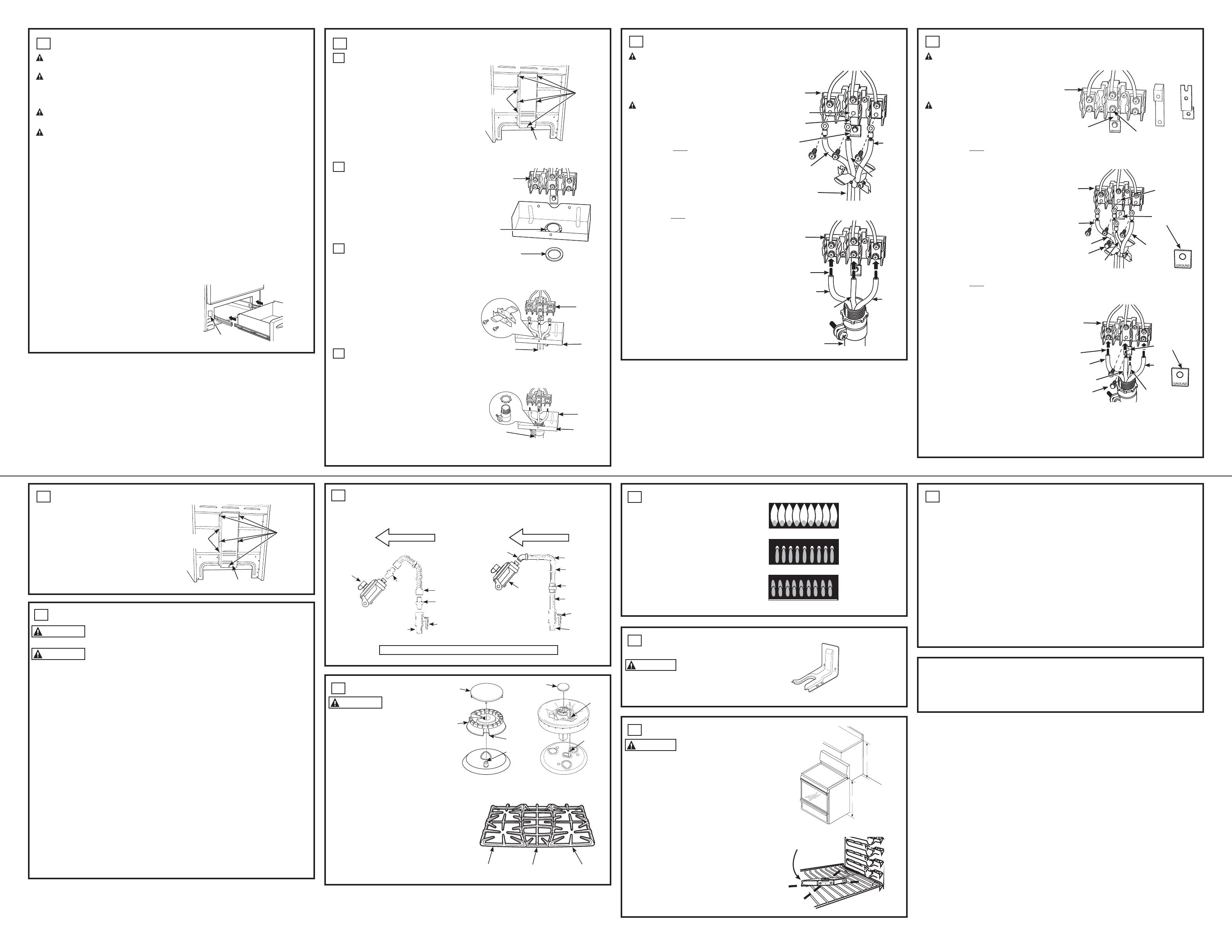
3-WIRE INSTALLATION (GROUND IS THROUGH THE NEUTRAL WIRE)
WARNING: Shock Hazard
The neutral wire and ground strap must be
connected as shown below for the range to be
properly grounded. Do not remove the ground
strap. Failure follow this instruction may result
in potential shock hazard.
WARNING: Fire hazard
Terminal block screws must be securely
tightened. Failure to do so may result in potential
fire hazard.
FOR POWER CORD INSTALLATION
A. Remove the 3 lower screws from the terminal
block. Do not loosen the upper screws.
B. Do not cut or remove the ground strap.
C. Insert the 3 screws through each power cord
terminal ring and back into the terminal block.
Be certain the white wire is in the center.
Securely tighten each screw (35 to 50 in-lbs.)
FOR CONDUIT INSTALLATION
A. Loosen the 3 lower screws on the terminal
block. Do not loosen the upper screws.
B. Do not cut or remove the ground strap.
C. Insert the bare wire tip (insulation stripped
5/8”) into the bottom terminal block openings.
Be certain the white wire is in the center. On
certain models, the wire must be inserted
through an opening in the ground strap.
Securely tighten each screw onto each wire
(35 to 50 in-lbs.).
NOTE: Aluminum building wire may be used but
it must be rated for the correct amperage and
voltage.
PROCEED TO STEP 5
4
4-WIRE INSTALLATION (SEPARATE GROUND WIRE)
WARNING: Shock Hazard
The neutral wire and ground strap must be
connected as shown below for the range to
be properly grounded. Do not remove the
ground strap. Failure follow this instruction
may result in potential shock hazard.
WARNING: Fire hazard
Terminal block screws must be securely
tightened. Failure to do so may result in
potential fire hazard.
FOR POWER CORD INSTALLATION
A. Remove the 3 lower screws from the
terminal block. Do not loosen the upper
screws.
B. Remove the ground screw and ground plate
and retain them.
C. Cut the ground strap below the terminal
block and discard the lower section.
D. Insert the ground screw through the ground
plate (removed earlier) and back into the
range frame. Tighten securely, but do not
over-tighten (15 to 20 in-lbs.)
E. Insert the 3 terminal screws through each
power cord terminal ring and back into the
terminal block. Be certain the white wire is
in the center. Securely tighten each screw
(35 to 50 in-lbs.
FOR CONDUIT INSTALLATION
A. Remove the 3 lower screws from the terminal
block. Do not loosen the upper screws.
B. Remove the ground screw and ground plate
and retain them.
C. Cut the ground strap below the terminal block
and discard the lower section.
D. Insert the bare ground bare wire tip (insulation
stripped 5/8”) between the range frame and
the ground plate (removed earlier) and secure
it in place with the ground screw. Tighten
securely, but do not over-tighten (15 to 20
in-lbs).
E. Insert the wire tips (insulation stripped 5/8”)
into the bottom terminal block openings. Be
certain the white wire is in the center. On
certain models, the wire must be inserted
through an opening in the ground strap.
Securely tighten each screw onto each wire
(35 to 50 in-lbs.)
NOTE: Aluminum building wire may be used but
it must be rated for the correct amperage and
voltage.
Ground
strap
Terminal block
(appearance
may vary)
Neutral
terminal
Power cord
Ground
plate
Power Cord
Wire
tips
Terminal
block
Conduit
Conduit
Red or
Black
Red or
Black
Red or
Black
Red or
Black
White
White
Terminal
block
Red or
Black
Red or
Black
Neutral
terminal
Ground plate
(grounding to
range)
Ground
screw
After–Power Cord
Green
or Bare
White
Before–Power Cord and Conduit
Terminal
block
Neutral
terminal
Ground
strap
Ground strap
or
After–Conduit
Terminal
block
Ground plate
(grounding to
range)
Wire
tips
Ground
screw
Red or
Black
Red or
Black
White
Green
or Bare
5
REPLACE THE WIRE COVER
Replace wire cover on range back by sliding
its left edge under the retaining tabs and
replace the screws removed earlier. Make
sure that no wires are pinched between
cover and range back.
Rating plate
SINGLE OVEN
7
SURFACE BURNERS
WARNING Fire or Explosion Hazard:
Do not operate the burner without all burner
parts in place.
A. Burners - Place surface burners into
corresponding positions on cooktop.
B. Caps - Place caps on proper size burner..
C. Continuous Grates - Place the left and
right grates on the cooktop. These grates
are marked “LEFT” and “RIGHT” on their
undersides. Place the center grate with its
short edge toward the front of the range.
Left RightCenter
or
Front right burner
Make sure the notch in the
burner head is positioned
over the electrode.
Electrode
Electrode
Hole
Notch
Cap
Burner
Cap
Power cord
Strain relief
Terminal
block
Bracket
Squeeze
connector
Terminal
block
Conduit
Bracket
Back of range
Back of range
10
LEVEL THE RANGE
WARNING
Never completely remove the
leveling leg as the range will not be secured to
the anti-tip device properly.
A. Plug in the unit.
B. Measure the height of your countertop at the
rear of the opening (X).
C. Adjust two rear leveling legs so that the rear of
cooktop is at the same height as the counter (Y).
D. Slide unit into place.
E. Install oven shelves in the oven and position the
range where it will be installed.
F. Check for levelness by placing a spirit level on
RQHRIWKHRYHQVKHOYHV7DNHWZRUHDGLQJV³ZLWK
the level placed diagonally first in one direction
and then the other.
G. Adjust front leveling legs until the range is level.
H. Look under the unit and verify that the rear leg
is fully engaged with the anti-tip device. If not,
remove the unit and adjust the height of the
rear leg so that it is properly engaged.
Spirit level
X
Y
31-10889-2 10-13 GE


