Page is loading ...

F-995-H
May, 2009
INSTRUCTIONS for
Be sure this information reaches the operator.
You can get extra copies through your supplier.
F-995-H
I. GAS SUPPLY AND REGULATION
REQUIREMENTS
A. PRESSURES
The C-65 can be used with any fuel gas other than
acetylene, such as natural gas, propane, and many
proprietary gases. Fuel gas pressures of 5 to 20 psi
are adequate for scarfing.
The C-65 operates most efficiently under normal con-
ditions with an oxygen pressure of 45 psi at the torch
inlet. The torch is adjusted at the factory for this condi-
tion. Under unusual operating conditions, pipeline size
and/or pressure may be inadequate to provide oxygen
at this level. Under such conditions, a slight opening
of the compensator valve (located in the torch body)
may be necessary. Instructions for adjusting the com-
pensator valve are given in section III-A.
B. HOSE SIZES
To obtain an oxygen pressure of 45 psi at the torch,
the regulator must be set to a pressure sufficiently high
to allow for the pressure drop through the hose. To
avoid excessive pressure drop 1/2 inch hose and stan-
dard OXWELD “C” size hose fittings, such as P/N
2120399 (50-ft.), must be used. Hose larger than 1/2
inch may be required where lengths greater than 75
feet are used.
These INSTRUCTIONS are for experienced operators. If you are not fully familiar with the principles of operation and safe prac-
tices for oxy-fuel gas equipment, we urge you to read our booklet “Precautions and Safe Practices for Welding, Cutting and
Heating”, Form 2035. Do NOT permit untrained persons to install, operate, or maintain this equipment. Do NOT attempt to install
or operate this equipment until you have read and fully understand these instructions. If you do not fully understand these
instructions, contact your supplier for further information.
The cutting torch covered by these instructions is listed by third parties only when using parts manufactured by ESAB
Welding & Cutting Products, to the specifications on file with third party listed, and when they are used in the gas service for
which they are designed and listed. The use of other parts voids the manufacturer’s warranty.
C-65 SCARFING TORCH
With 50 feet of 1/2 inch hose, the approximate pres-
sure drop will be 60 psi. The regulator must therefore
be set to a delivery pressure of approximately 105 psi.
With 75 feet of 1/2 inch hose, the approximate pres-
sure drop will be 90 psi. The regulator must therefore
be set to a delivery pressure of approximately 135 psi.
Fuel gas hose should be 3/8 inch with “B” size fittings,
such as P/N 2120404 (50-ft.).
Also available is a fitted 65-ft. Scarfing Hose Assembly,
P/N 2119324, which includes 50-ft. of 3/4" hose with
“D” size fitting on one end for connecting to oxygen
regulator spliced with 15-ft. of 1/2” hose with “C” fitting
for torch connection, and 65-ft. of 3/8" fuel gas hose
with “B” size fittings.
C. STATION REGULATOR PANEL, P/N 2119101
This regulator panel includes the R-52 Oxygen Regu-
lator (20A16) and the R-76-75-025 Fuel Gas Regulator
(19153) conveniently mounted on a frame for wall
mounting. The panel also includes shutoff and check
valves, oxygen line filter, and gas safety valve.
The R-52 Oxygen Regulator has ample capacity to meet
gas flow requirements under normal operation condi-
tions. However, to obtain the required delivery pressure
at the regulator, the line pressure ahead of the regula-

BE SURE THIS INFORMATION REACHES THE OPERATOR.
YOU CAN GET EXTRA COPIES THROUGH YOUR SUPPLIER.
SAVE THESE INSTRUCTIONS!
IMPORTANT SAFEGUARDS
When using Oxy-Fuel Gas Torches, basic safety precautions should always be followed:
Never use Acetylene gas at a pressure over 15 psig.a.
Never use damaged equipment.b.
Never use oil or grease on or around Oxygen equipment.c.
Never use Oxygen or fuel gas to blow dirt or dust o clothing or equipment.d.
Never light a torch with matches or a lighter. Always use a striker.e.
Always wear the proper welding goggles, gloves and clothing when operating Oxy-Acetylene equipment. f.
Pants should not have cus.
Do not carry lighters, matches or other ammable objects in pockets when welding or cutting.g.
Always be aware of others around you when using a torch.h.
Be careful not to let welding hoses come into contact with torch ame or sparks from cutting.i.
SAVE THESE INSTRUCTIONS.j.
This equipment will perform in conformity with the description thereof contained in this manual and accompa-
nying labels and/or inserts when installed, operated, maintained and repaired in accordance with the instruc-
tions provided. This equipment must be checked periodically. Malfunctioning or poorly maintained equipment
should not be used. Parts that are broken, missing, worn, distorted or contaminated should be replaced imme-
diately. Should such repair or replacement become necessary, the manufacturer recommends that a telephone
or written request for service advice be made to the Authorized Distributor from whom it was purchased.
This equipment or any of its parts should not be altered without the prior written approval of the manufacturer.
The user of this equipment shall have the sole responsibility for any malfunction which results from improper
use, faulty maintenance, damage, improper repair or alteration by anyone other than the manufacturer or a ser-
vice facility designated by the manufacturer.
These INSTRUCTIONS are for experienced operators. If you are not fully familiar with the prin-
ciples of operation and safe practices for gas welding and cutting equipment, we urge you to read
our booklet, “Precautions and Safe Practices for Gas Welding, Cutting, and Heating,” Form F-2035.
Do NOT permit untrained persons to install, operate, or maintain this equipment. Do NOT attempt
to install or operate this equipment until you have read and fully understand these instructions. If
you do not fully understand these instructions, contact your supplier for further information. Be
sure to read the Safety Precautions before installing or operating this equipment.
CAUTION
USER RESPONSIBILITY
READ AND UNDERSTAND INSTRUCTION MANUAL BEFORE INSTALLING
OR OPERATING. PROTECT YOURSELF AND OTHERS!

2
These Safety Precautions are for your protection. They sum-
marize precautionary information from the references listed
in Additional Safety Information section. Before performing any
installation or operating procedures, be sure to read and fol-
low the safety precautions listed below as well as all other
manuals, material safety data sheets, labels, etc. Failure to ob-
serve Safety Precautions can result in injury or death.
PROTECT YOURSELF AND OTHERS - Some
welding, cutting and gouging processes are
noisy and require ear protection. Hot metal can
cause skin burns and heat rays may injure
eyes. Training in the proper use of the pro-
cesses and equipment is essential to prevent
accidents. Also:
1. Always wear safety glasses with side shields in any work area,
even if welding helmets, face shields, or goggles are also re-
quired.
2. Wear flameproof gauntlet type gloves, heavy long-sleeve shirt,
cuffless trousers, high-topped shoes, and a welding helmet or
cap for hair protection, to protect against hot sparks and hot
metal. A flameproof apron may also be desirable as protection
against radiated heat and sparks.
3. Hot sparks or metal can lodge in rolled up sleeves, trousers
cuffs, or pockets. Sleeves and collars should be kept buttoned,
and open pockets eliminated from the front of clothing.
4. Protect other personnel from hot sparks with a suitable non-
flammable partition or curtains.
5. Use goggles over safety glasses when chipping slag or grind-
ing. Chipped slag may be hot and can travel considerable dis-
tances. Bystanders should also wear goggles over safety
glasses.
FIRES AND EXPLOSIONS - Heat from a flame
can act as an ignition source. Hot slag or sparks
can also cause fires or explosions. Therefore:
1. Remove all combustible materials well away from the work
area or completely cover the materials with a protective non-
flammable covering. Combustible materials include wood,
cloth, sawdust, liquid and gas fuels, solvents, paints and coat-
ings, paper, etc.
2. Hot sparks or hot metal can fall through cracks or crevices in
floors or wall openings and cause a hidden smoldering fire on
the floor below. Make certain that such openings are protected
from hot sparks and metal.
3. Do not weld, cut, or perform any other hot work on materials,
containers, or piping until it has been completely cleaned so
that no substances on the material can produce flammable or
toxic vapors. Do not do hot work on closed containers. They
may explode.
4. Have fire extinguishing equipment handy for instant use, such
as a garden hose, a pail of water or sand, or portable fire
extinguisher. Be sure you are trained in its use.
5. After completing operations, inspect the work area to be sure
that there are no hot sparks or hot metal which could cause a
later fire. Use fire watchers when necessary.
6. For additional information, refer to NFPA Standard 51B, Fire
Prevention in Use of Cutting and Welding Processes, which
is available from the National Fire Protection Association,
Batterymarch Park, Quincy, MA 02269.
FUMES AND GASES - Fumes and gases, par-
ticularly in confined spaces, can cause dis-
comfort or injury. Do not breathe fumes or
gases from welding or cutting, Therefore:
1. Always provide adequate ventilation in the work area by natu-
ral or mechanical ventilation means. Do not weld, cut, or gouge
on materials such as galvanized steel, stainless steel, copper,
zinc, lead, beryllium, or cadmium unless positive mechanical
ventilation is provided. Do not breathe fumes and gases from
these materials.
2. If you develop momentary eye, nose, or throat irritation while
operating, this is an indication that ventilation is not adequate.
Stop work at once and take necessary steps to improve venti-
lation in the work area. Do not continue to operate if physical
discomfort persists.
3. Refer to ANSI/ASC Standard Z49.1 listed below for specific
ventilation recommendations.
EQUIPMENT MAINTENANCE - Faulty or improperly
maintained equipment, such as torches, hoses and
regulators, can result in poor work, but even more
important, it can cause injury or death through fires.
Therefore:
1. Always have qualified personnel perform the installation,
troubleshooting, and maintenance work. Do not operate or
repair any equipment unless you are qualified to do so.
2. Keep all oxy-fuel equipment free of grease or oil. Grease, oil,
and other similar combustible materials, when ignited, can burn
violently in the presence of oxygen.
3. Do not abuse any equipment or accessories. Keep equipment
away from heat and wet conditions, oil or grease, corrosive
atmospheres and inclement weather.
4. Keep all safety devices in position and in good repair.
5. Use equipment for its intended purpose. Do not modify it in
any manner.
GAS CYLINDER HANDLING - Gas cylinders, if
mishandled, can rupture or explode violently.
Sudden rupture of a cylinder, valve or relief de-
vice can injure or kill you. Therefore:
1. Use the proper gas for the process and use the proper pres-
sure reducing regulator designed to operate from the com-
pressed gas cylinder. Do not use adaptors to mount the regu-
lator on the cylinder. Maintain hoses and fittings in good con-
dition. Follow manufacturers operating instructions for mount-
ing the regulator to the gas cylinder.
2. Always secure cylinders in an upright position by chain or strap
to suitable hand trucks, benches, walls, post, or racks. Never
secure cylinders to work tables or fixtures where they may
become part of an electrical circuit.
3. When not in use, keep cylinder valves closed. Have the valve
protection cap in place on top of the cylinder if no regulators is
installed. Secure and move cylinders by using suitable hand
trucks. Avoid rough handling of cylinders.
4. Locate cylinders away from heat, sparks, or flame of a weld-
ing, cutting, or gouging operation. Never strike an arc on a
cylinder.
5. For additional information, refer to CGA Standard P-1, Pre-
cautions for Safe Handling of Compressed Gases in Cylin-
ders:, which is available from the Compressed Gas Associa-
tion, 1235 Jefferson Davis Highway, Arlington, VA 22202.
ADDITIONAL SAFETY INFORMATION - For more in-
formation on safe practices for oxy-fuel welding and
cutting equipment, ask your distributor for a copy of
Precautions and Safe Practices for Gas Welding, Cut-
ting, and Heating, Form 2035. Gas apparatus safety
guidelines are also available on video cassettes from
your distributor.
The following publications, which are available from the American
Welding Society, 550 N.W. LeJuene Road, Miami, FL 33126, are
recommended to you:
1. ANSI/AWS Z49.1 - Safety in Welding and Cutting.
2. AWS F4.1 - Recommended Safe Practices for the Prepara-
tion for Welding and Cutting of Containers and Piping That
Have Held Hazardous Substances/
3. AWS SP - Safe Practices - Reprint, Welding Handbook.
Used to call attention to immediate hazards
which, if not avoided, will result in immediate,
serious personal injury or loss of life.
Used to call attention to potential hazards
which could result in personal injury or loss of
life.
Used to call attention to hazards which could
result in minor personal injury.
This symbol appearing in this manual means
Attention! Be Alert! Your safety is involved.
SP-GA 7/97
SAFETY PRECAUTIONS


3
reduce the pressure drop between the regulator and
torch at normal operating flows.
Attach an 1809, size 62 nozzle (see Table 1) to torch
head, and tighten the connection nut firmly with a
wrench. Insert the starting rod (steel rod, .178 to .195
in. in diameter) in the rear end of the rod feed body.
Remove end burrs from starting rod prior to inserting.
The rod must move freely. Slide it forward until the end
is even with the tip of the nozzle. A 3/16" diam. x 36"
long OXWELD No. 7 rod, Part No. 1031F15 (50 lb.
package), is recommended, mainly because of its free-
dom from burrs and uniformity in size.
B. TO ADJUST PRESSURES
Oxygen Pressure
If individual station regulators are used, connect an
OXWELD test gauge adaptor (Part No. 21X48) be-
tween the oxygen hose and the torch. Set the delivery
pressure on the oxygen regulator at 105 psi if using
50-ft. of hose, or at 135 psi if using 75-ft. of hose. Open
the torch cutting oxygen valve and turn the pressure-
adjusting screw on the regulator until the test gauge
Cutting Oxygen Natural Gas
Inlet Inlet Flow,
Pressure Flow Pressure cfh
psig (bars) cfh (m
3
/hr) psig (bars) (m
3
/hr)
20 (1.38) 4300 (123) 5 (0.35) 40 (1.13)
30 (2.07) 5600 (159) 10 (0.69) 75 (2.12)
40 (2.76) 7000 (198) 15 (1.04) 105 (2.97)
50 (3.45) 8300 (235) 20 (1.38) 130 (3.68)
60 (4.14) 9600 (272)
Oil or grease is easily ignited and burns violently in the presence of oxygen under pressure. Handle
oxygen apparatus only with clean hands or gloves. Never use oxygen as a substitute forcompressed air.
TABLE II
Gas Pressure & Consumption Data – 1809 Series, Size No. 62 (P/N 15X70)
(Pressure measured at the torch inlet connection)
TABLE I – Nozzle Information – 1809 Series
Nozzle Scarfing Preheat Cleaning Drill Size Replacement Parts
Path Holes
Width Wear Ring Nozzle
Size Part No. Preheat Cutting Assembly Nut
62 15X70 2-1/4” – 3-3/16” 16 1/16” 5/8” 60Y92 37Z23
(57 – 81mm)
tor must be at least 10 lb. per sq. inch greater — that
is, at least 145 lb. per sq. in. (135 + 10).
The R-76-75-025 Fuel Gas Regulator is designed for
high flow delivery of fuel gas.
D. CENTRAL REGULATION
If the oxygen supply is regulated from a central point in
a distribution line piping system, the R-83-40M Oxy-
gen Station Regulator should be used. A single unit is
usually sufficient, but several units may be required.
Where operations are continuous and extremely heavy,
an OXWELD R-600 Series Station Regulator may be
needed.
II. OPERATING INSTRUCTIONS
A. TO CONNECT
Check that the packing nuts on the torch valves are
snug. Attach the oxygen and fuel gas hoses to the torch.
Use 1/2-in. hose for the oxygen supply and 3/8 in. hose
for the fuel gas supply. Where lengths of hose greater
than 75-ft. are desired, it may be necessary to use a
section of larger than 1/2-in. hose in the oxygen line to

4
shows a pressure of 45 lb. per sq. in. Note the exact
pressure on the regulator gauge. Then release the pres-
sure-adjusting screw of the regulator, release the torch
cutting oxygen valve, and remove the test gauge from
the line. Readjust the regulator (with the torch cutting
valve open) until it shows the pressure noted during
the test and then close the cutting oxygen valve.
Fuel Gas Pressure
Open the torch fuel gas valve and adjust the fuel gas
delivery pressure at the regulator to between 10 and
20 psig.
C. TO LIGHT THE TORCH
Open the preheat oxygen valve just enough to provide
a slight flow of preheat oxygen. Open the fuel gas valve
one turn. Light the gas at the nozzle with a friction lighter.
Adjust the flames with the preheat oxygen valve. Then
open the cutting oxygen valve. If the flames blow away
from the nozzle or blow away as soon as lit, close the
fuel gas valve slightly, or if operations are controlled
from the main line, reduce the fuel gas line pressure.
Tables 1 and 2 give operating data as well as other
useful information that will be helpful in the normal use
of the C-65 torch. Cleaning drill sizes are specified in
Table 1, and the oxygen and fuel gas flows for a range
in operating pressure are given in Table 2 so as to give
an indication of actual gas usage.
The cutting oxygen pressure should normally be set at
45 psi with the cutting oxygen valve wide open so as to
obtain a reasonably wide scarfing path width. The fuel
gas pressure should be set at the high end of the range,
although at times the available pressure at the supply
station will be the controlling factor. When the torch
pressures and torch valve adjustments (including the
adjustment of the preheat oxygen compensator valve)
are properly set, the preheat flames will be stable and
should not blow off the end of the nozzle as the cutting
oxygen lever is fully depressed and then released. The
high velocity flames, pale in color (oxidizing), should
be just below the blow-off point when the cutting oxy-
gen valve is closed.
D. TO FEED THE STARTING ROD
With the rod adjusted until the end almost touches the
preheat flames, press the torch cutting oxygen lever
about halfway down. This movement feeds the rod,
but does not open the cutting oxygen valve. Hold the
lever at the halfway position until the rod is heated;
then just push the lever all the way down to open the
cutting oxygen valve. During the latter half of the stroke,
the rod remains stationary.
To feed the rod independent of the cutting oxygen, limit
the movement of the valve lever to about half a stroke.
To operate the cutting oxygen valve independently of
the rod feed, confine the lever movement to the lower
half of the stroke — as would be desirable for fin burn-
ing.
E. TO SHUT OFF
First close the torch fuel gas valve, then the torch oxy-
gen cutting valve.
F. OPERATING PRECAUTIONS
Improper handling of the torch may cause the flame to
backfire — go out with a loud snap. This may be caused
by overheating the nozzle, by operating the torch at
incorrect pressures, by a loose nozzle or by dirt on the
nozzle seat. Should the flame flash back — burn in-
side the torch — immediately close the oxygen valve.
Then close the fuel gas valve. After checking the ap-
paratus for causes of flashback indicated above, re-
light the torch in the usual manner. If flashbacks occur
repeatedly, the torch should be sent to ESAB
Remanufacturing Center, 411 S. Ebenezer Road, Flo-
rence, SC 29501, or to your distributor.
III. MAINTENANCE INSTRUCTIONS
For all repairs other than those covered below,
send the apparatus to ESAB Remanufacturing
Center, 411 S. Ebenezer Road, Florence, SC
29501. Improperly repaired apparatus is hazard-
ous.
A. TORCH
1. The Preheat-Oxygen Compensator Valve
Replacement of any of these parts will require re-
adjustment of the compensator valve stem, as fol-
lows:
a. Turn the adjustable stem in (clockwise) as far
as it will go.
b. Set the oxygen and fuel gas pressures, and
light the torch in the usual manner.
c. Open the fuel gas valve wide, and adjust the
preheat oxygen valve until a high velocity
pointed flame is obtained.
d. Open the torch cutting oxygen valve. The pre-
heat flames will become longer and blow off,
indicating a lack of preheat oxygen. Hold the
cutting oxygen valve open and adjust the com-
pensator stem outward (counterclockwise),
until the preheat flames show a minimum of
change when the cutting oxygen valve is
opened and closed.
e. Any change in the cutting oxygen pressure at
the torch will require readjustment of the com-
pensator stem. An increase in pressure will re-
quire an inward (clockwise) adjustment, a de-
crease in pressure will require an outward
(counterclockwise) adjustment.

5
(92Z66) from lever (25Z56). Remove lever
from torch.
b. Unscrew valve stem guide (637431) from the
valve body and carefully remove the cutting
valve assembly.
c. Using soapy water, moisten the cutting valve
stem (48Z67) through the stem guide and slide
the stem out of the guide.
d. Remove the “O” ring seal (85W70), spring
washer (637430), “O” ring (86W70) and valve
spring (29Z37) from the valve stem. Discard
the “O” rings.
e. Remove seat retaining screw (6124-4880),
washer (94Z08), and valve seat (52Z89) from
the bottom of the valve stem. Discard the old
valve seat.
f. Carefully clean and examine valve stem,
spring, guide, locknut and adjusting screw for
damage and excessive wear. Replace parts
as necessary.
g. Install new valve seat (52Z89) (flat face in) and
secure in place with washer and screw.
h. Place new brass washer (94Z08) (countersink
out) against seat.
i. Install valve spring on top of upper valve shoul-
der, and slide washer on top of the spring.
j. Apply a light coat of DuPont Krytox 240
(73585064) on a new “O” ring seal (85W10)
and (86W70) and slide the “O” rings in place.
k. Carefully slide the stem guide on the valve
stem, over the spring washer and “O” ring
(85W10).
l. Insert the valve assembly in the torch valve
body and tighten the valve guide until it seats
firmly.
m. Install the cutting valve lever on the torch and
secure with the lever bushing, retaining screw
and nut.
B. START ROD FEEDER
1. Off-the-Nozzle Adjustment
The rod feed body can be adjusted up or down for
varying the distance between the nozzle face and
the starting rod. An eccentric bolt (34Z89) and hold-
ing bolt (61641028) are provided for this adjust-
ment. The two locknuts (186W59) are first loos-
ened slightly and then the eccentric bolt can be
turned until the desired distance between nozzle
face and starting rod is obtained. Tighten the two
locknuts firmly
2. To Replace Feed Block, Spring, and Guide
Block
To make these replacements, first remove the rod
feed bottom cover (31Z76) by unscrewing the guide
screw (37Z59). Then remove the guide block
(39Z68) by unscrewing the attaching screw (34Z57)
2. Floating Mixer
If the mixer becomes clogged, it may be removed
for cleaning as follows:
Unscrew the body plug between the two hose con-
nections to the rear body. Remove the spring which
holds the mixer in place. Screw a standard No. 10-
32 machine screw, two inches or more in length,
into the rear of the mixer and pull out the mixer. To
clean the mixer, use a No. 35 drill (0.110 in. diam-
eter) or a soft brass or copper wire; other tools
might enlarge or bell-mouth the orifice, hence they
should not be used.; If the mixer is bent, or if its tip
has been badly nicked or marred, it should be re-
placed by a new one.
Whenever the mixer is removed from the torch,
the “O” ring should be replaced with a new one.
Apply a light coat of soap film to the surface of the
“O” ring and then insert the mixer carefully (with a
twisting motion) into the torch to avoid damage to
the “O” ring.
3. To Reseat the Head
For reseating the head, use Tool No. 5230089 with
Leak Test Solution (998771) as lubricant. If the
nozzle nut threads in the head become fouled, they
should be chased with a 1 3/8" - 18 tap, Tool No.
5240061.
4. Fuel Gas or Preheat-Oxygen Valves
If leakage develops around the valve stems or if
they turn too easily, tighten the packing nuts. If this
does not help, replace the valve stem assembly.
To seal the new valve stem assembly properly, the
packing material should be molded in place. To do
this, the packing nut should be tightened until it is
difficult to turn the valve. Set the torch aside for 3
or 4 hours (preferably overnight), then back off the
packing nut slightly until the proper friction is ob-
tained for satisfactory valve adjustment. Test valve
leakage around the nut and stem when the friction
has been adjusted to the desired amount. If either
torch valve does not shut off tightly, remove the
valve stem assembly. Wipe the seating portions of
the valve stem and body with a clean cloth. If the
valve stem is damaged, the stem assembly should
be replaced. If the valve still leaks, the valve should
be reseated at ESAB Remanufacturing Center.
5. Cutting Oxygen Valve
If leakage develops through the cutting valve, re-
place the valve seat. If leakage is around the valve
stem, replace the stem “O” ring seal. Proceed as
follows to replace these parts:
a. Remove cutting lever mounting nut (186W58),
retaining screw (34Z91), and lever bushing

6
with a socket wrench. Examine all parts for wear
and distortion, and replace where needed. Parts
most frequently requiring replacement will be feed
block spring (28Z47) and the spring (28Z82) and
balls (90A13) in guide block (39Z69). If guide block
shows wear, it should also be replaced.
Replacement of guide block spring and balls can
be accomplished by first prying the spring (28Z82)
out of the confining groove in the guide block. The
two balls should fall free of the guide block. Install
two new balls and new spring. Make sure the hole
in the spring is centered over the countersink re-
cess in the block groove. Carefully insert the guide
block in rod feed body recess, with center bore
approach taper facing out, and the hole in the spring
and countersink recess in the guide block in line
with the screw hole of the rod feed body. Replace
attaching screw (34Z57), making sure the point of
screw enters countersink recess in block for proper
engagement. Tighten attaching screw securely, but
do not overtighten.
3. Rod Feed Mechanism Replacements
To replace rod feed lever (25Z52), spring (29Z25),
pull rod (150Z39), or the entire rod feed assembly
(63Y31), the rod feed assembly must be removed
from the mounting bracket (150Z37). Proceed to
do the following:
a. Remove the snap ring (202-8372) and then
the clevis pin (93Z42) from the side arm of the
cutting lever (25Z56).
b. Remove the four handle screws (61332996)
and slide the handle (24Y28) down to the tube
bracket (71Z94).
c. Remove the rod feed eccentric bolt (34Z89)
and holding bolt (61641028). Pull the feed rod
assembly toward the torch head until pin
(636203) that fastens pull rod lever (25Z52) is
exposed. Remove pin to free the rod feed as-
sembly from the torch.
d. Pull rod can now be pulled back enough
through the handle to replace spring (29Z77)
if required. If replacing pull rod, unscrew clevis
(71Z66) from the end of the rod and then re-
move the pull rod by pulling from the head end
of the torch.
e. To remove rod feed lever (25Z52) and spring
(29Z25), drive out pin (185W02) from either
side of rod feed body. Make sure the rod feed
body is amply supported on the bottom.
f. Reassemble all parts in reverse order. Before
connecting the rear end of pull rod to the cut-
ting lever side arm, the rod feed body should
be firmly attached to the mounting bracket. It
should be positioned so that a section of a
3/16" rod, when inserted in the rod feed, clears
the end of the torch nozzle by approximately
1/8" and directly over the maximum number
of preheat ports.
g. The pull rod assembly should be adjusted so
that the hole in the offset link, (150Z42) is in
line with the hole in the side arm of the cutting
lever. Only a very slight slack should remain in
the pull rod assembly.
h. If the rod does not feed properly after com-
pleting assembly, look for any points of bind-
ing between pull rod and torch.
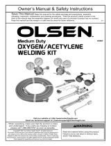
C. REPLACEMENT PARTS
The 48-inch long torch is made up from the basic 42-
inch long torch. This is accomplished by coupling the
correct length extensions to the oxygen and mixer tubes
to make up the extra length. Thus all parts shown in
the C-65 (42-inch) parts picture are common to the 48-
inch torch. The sketch in Fig. 1 shows the coupling
and extensions used on the 42 and 48-inch torches.
C-65 TORCHES
Part No. Description
27X47 42 in. Long Torch with Rod Feed Mecha-
nism
27X48 48 in. Long Torch with Rod Feed Mecha-
nism
ACCESSORIES
Part No. Description
21X48 “C” size 200 lb. Gauge Adaptor Assembly
33Y64 C-65 Compensator Valve for conversion
(Includes 85W10, 48Z41 and 83Z26)
163Z25 Lubricant 151-L, for Valve Threads
526581 Mixer for use with low pressure natural gas
7358-5064 DuPont Krytox 240 Anti-Friction Com-
pound, for “O” Rings
HARDWARE
Part No. Description
6124-4880 8-32 x 1/2 in. Long Flat Head Screw, Steel
6133-2996 6-32 x 5/16 in. Long Oval Hd. Self-Tap-
ping Screw, Parker-Kalon Type “F”
6164-1028 1/4-28 x 1-5/16 in. Long Hex. Head
Capscrew, Stainless Steel
636203 7/64” I.D. x 27/64” lg. x .047” thick Cotter
Hairpin


7
Fig. 1A – C-65 Scarfing Torch –27X47 – 42 in. long
27X48 – 48 in. long
“C”
“C”
BOLT – 34Z89
SCREW – 6164-1028
WASHER – 82Z34
(2) NUT – 186W59
“A”
(4) SCREW – 6163-2996
“A”
SEE VIEW “E”
HANDLE – 24Y28
35 -1/8” (27X47)
39 -1/4" (27X48)
BRACKET – 71Z94
SILVER SOLDER
BRACKET – 151Z06
NUT
186W58
BUSHING
92Z66
LEVER SCREW - 34Z91
BSHING
2222859
"O" RING - 85W10
PLATE - 637430
"O" RING - 86W70
GUIDE - 637431
"O" RING - 96W97
SPRING - 29Z37
STEM - 48Z67
GAS TIGHT SEAT
SCREW - 6124-4880
(2) GAS TIGHT
SEAT
ADJUSTING SCREW - 134Z06
SEAT - 52Z89
(2) STEM ASSEMBLY - 54A87
WASHER - 94Z08
HEAD – 83Z97
(INCLUDES)
SLEEVE – 92Z67
BOTTOM TUBE AT THIS END
PEEN TUBE BEFORE ASSEMBLING
SILVER SOLDER
LEVER – 25Z56
SLEEVE
27Z88
1-3/8 – 18
MIXER NOZZLE – 01Y43
(INCLUDES)
“O” RING – 84W85
OXYGEN TUBE – 27Z45
MIXER TUBE ASSEMBLY – 16Y87
(INCLUDES)
MIXER THROAT – 17Z75
SILVER SOLDER
TUBE MUST BOTTOM
BODY – 80Z10
SEE VIEW “D”
SEE ENLARGED VIEWS "F" AND "G"
VIEW "A"-"A"
VIEW "B"-"B"
3/4 - 20
NUT - 136Z18
APPLY ANTI FRICTION COMPOUND
PART NO. 163Z25
3/8"-24


F-995-H 05 / 2009 Printed in U.S.A.
SCREW -
34Z91
BUSHING -
92Z66
NUT - 186W58
BUSHING -
2222859
"B"
"B"
CLEVIS PIN - 93Z42
SNAP-RING - 202-8372
FUEL
CONNECTION
999082
OXYGEN
CONNECTION
10Z82
7/8 - 14
SILVER SOLDER
9/16 -
18 (L.H.)
"O" RING - 96W97
GAS TIGHT SEAL
PLUG
35Z91
5/8 - 25
VIEW "D"
"O" RING - 84W85
(Included In Mixer
Nozzle - 01Y43)
SPRING
28Z91
NOZZLE NUT –
37Z23
OXYGEN TUBE EXTENSION -
147Z13 (27X47)
147Z15 (27X48)
COUPLING - 150Z56
MIXER TUBE AND EXTENSION
MUST BOTTOM IN COUPLING
MIXER TUBE EXTENSION -
147Z14 (27X47)
147Z16 (27X48)
PULL ROD -
150Z40
150Z38
SLEEVE – 92Z67
(INCLUDED IN HEAD – 83Z97)
SPRING – 29Z25
PLATE – 150Z37
LEVER – 25Z52
PIN – 636203
PIN – 185W02
BODY – 100Z14
BLOCK – 51Z53
SCREW – 37Z59
SCREW – 34Z57
(2) BALL – 90A13
BLOCK – 39Z68
ROD FEED ASSEMBLY – 63Y31
VIEW "E"
3/8 - 28
"O" RING - 85W10
CLEVIS – 71Z66
SPRING – 29Z77
* NOT INCLUDED IN 63Y61, ORDER SEPARATELY
VIEW "F"
VIEW "G"
VIEW "C"
STEM - 48Z41
BODY - 83Z26
#10-32
SPRING - 28Z92
BALL - 53A61
*PULL ROD
150Z39
SPRING – 28Z47
CAP – 31Z76
SPRING – 28Z82
LINK - 150Z42
Figure 1B – C-65 Scarfing Torch
/