Miller Coolmate 3.5 Owner's manual

Category
Welding System
Type
Owner's manual

This manual is also suitable for

Miller Coolmate 3.5 is a recirculating coolant system compatible with water-cooled GTAW torches and GMAW guns rated up to 600 amperes. With a 3.5-gallon coolant tank capacity and a maximum cooling capacity of 15,000 BTU/hr, it can maintain a steady coolant flow rate of 1.25 quart per minute.

Miller Coolmate 3.5 is a recirculating coolant system compatible with water-cooled GTAW torches and GMAW guns rated up to 600 amperes. With a 3.5-gallon coolant tank capacity and a maximum cooling capacity of 15,000 BTU/hr, it can maintain a steady coolant flow rate of 1.25 quart per minute.

dec_cooler_1/07
© 2007 MILLER Electric Mfg. Co.
Declaration of Conformity for
European Community (CE) Products
. This information is provided for units with CE certification (see rating label on unit).
Manufacturer: European Contact:
Miller Electric Mg. Co. Mr. Danilo Fedolfi,
1635 W. Spencer St. Managing Director
Appleton, WI 54914 USA ITW Welding Products Italy S.r.l.
Phone: (920) 734-9821 Via Privata Iseo 6/E
20098 San Giuliano
Milanese, Italy
Phone: 39(02)98290-1
Fax: 39(02)98290203
European Contact Signature:
Declares that the product: CoolmateE 3.5
conforms to the following Directives and Standards:
Directives
Low Voltage Directive: 73/23/EEC, 2006/95/EC
Electromagnetic compatibility Directives: 89/336/EEC, 92/31/EEC, 2004/108/EC
Machinery Directives: 98/37/EEC, 91/368/EEC, 92/31/EEC, 133/04, 93/68/EEC
Marking Directive: 93/68/EEC
Standards
Arc Welding Equipment Part 2: Liquid Cooling Systems. IEC 60974-2 Ed. 1, 2202-06
Arc Welding Equipment Part 10: Electromagnetic Compatibility (EMC) Requirements. IEC 60974-10, Ed. 1.1, 2004-10
Degrees of Protection Provided By Enclosure (IP Code): IEC 60529 Ed. 2.1, 2001-02
Insulation Coordination For Equipment Within Low-Voltage Systems Part 1: Principles, Requirements, And Tests.
IEC 60664-1 Ed. 1.1
The product technical file is maintained by the responsible Business Unit(s) located at the manufacturing facility.
Additional Standards (Writer: Delete additional standards not applicable)
Arc Welding Equipment Part 2: Liquid Cooling Systems. IEC 60974-2 Ed. 1, 2002-06
3. Warning Labels
OM-231 313 Page 2
4. Warning Labels Continued
S-180 663
1 2 3 4 5
6
7 8 9
1 Warning! Watch Out! There are
possible hazards as shown by the
symbols.
2 Electric shock from wiring can kill.
3 Disconnect input plug or power before
working on machine.
4 Moving parts, such as fans, can cut
fingers and hands and cause injury.
Keep away from moving parts.
5 Wear safety glasses with side shields.
6 Read the Owner’s Manual before
working on this machine.
7 Read the labels on the welding power
source, wire feeder, or other major
equipment for welding safety
information.
8 Recycle or dispose of used coolant in
an environmentally safe way.
9 Do not remove or paint over (cover)
the label.
S-178 910
=
043 810 (HF)
043 809 (AL)
100 h. std.
21 3
6
4
7
5
1 Warning! Watch Out! There are
possible hazards as shown by the
symbols.
2 Disconnect input plug or power before
working on machine.
3 Wear safety glasses with side shields.
4 Plugged filter or hoses cause
overheating and damage.
5 Read Owner’s Manual.
6 Check and clean filter every 100
hours; also check condition of hoses.
7 Use Low Conductivity Coolant No. 043
810 for High-Frequency assisted or
Gas Tungsten Arc Welding
applications. Use Aluminum Protecting
Coolant No. 043 809 where coolant
contacts aluminum parts or for Gas
Metal Arc Welding applications or
where High Frequency is not used.
OM-231 313 Page 3
5. Rating Label
S/N: KG085472
043007
COOLMATE 3
Hz50/60
IP 23
U
1
=
I
1
=
1
NRTL/C
LR5071
231 308-B
6. Symbols And Definitions
Hz
Hertz Input Power Power On Indicator
Water (Coolant)
Output
Water (Coolant) In-
put
Line Connection
Single-Phase
Alternating
Current
U
1
Primary Voltage
I
1max
Rated Maximum
Supply Current
IP
Degree Of
Protection
P
max
Rated maximum
power
Pl/
min
Power liters per
minute
OM-231 313 Page 4
7. Coolant Chart
Low Conductivity Coolant No. 300 355**; Distilled Or Deionized Water OK Above 32° F (0° C)
GTAW Or Where
HF* Is Used
Application
*HF: High Frequency Current
**Coolant 300 355, a 50/50 solution, protects to -37° F (-38°C) and resist algae growth.
Coolant
NOTICE Use of any coolant other than that listed in the table voids the warranty on any parts that come in contact with the coolant (pump,
radiator, etc.).
Notes
OM-231 313 Page 5
8. GTAW Connections
804 846-A
Tools Needed:
5/8 in
1
2
3
4
To prevent overheating, make sure cooling
unit is positioned so airflow is not restricted.
NOTICE If welding power source has a
water valve, do not connect hoses to water
valve. Connect hoses as shown.
1 Coolant Out Hose
2 Coolant In Hose
Fittings have 5/8-18 left-hand threads.
Connect hoses with proper fittings as
shown. Some power sources may require
a TIG block.
3 Coolant Tank Cap
4 115 Volt AC Grounded Receptacle
An individual branch circuit capable of car-
rying 15 amperes and protected by fuses
or circuit breakers is recommended. Rec-
ommended fuse or circuit breaker size is
15 amperes.
Operation:
Fill tank with proper coolant. Use table in
Section 7 to select proper coolant. Maintain
coolant level at approximately 1 in (25 mm)
below top of filler neck. Connect hoses as
shown. Unit turns on when plugged in.
OM-231 313 Page 6
9. GMAW Connections
804 845-A
Tools Needed:
5/8 in
To prevent overheating, make sure cooling
unit is positioned so airflow is not restricted.
NOTICE If welding power source has a
water valve, do not connect hoses to water
valve. Connect hoses as shown.
1 Coolant Out Hose
2 Coolant In Hose
Fittings have 5/8-18 left-hand threads.
Connect hoses with proper fittings as
shown.
3 Coolant Tank Cap
4 115 Volt AC Grounded Receptacle
An individual branch circuit capable of car-
rying 15 amperes and protected by fuses
or circuit breakers is recommended. Rec-
ommended fuse or circuit breaker size is
15 amperes.
Operation:
Fill tank with proper coolant. Use table in
Section 7 to select proper coolant. Maintain
coolant level at approximately 1 in (25 mm)
below top of filler neck. Connect hoses as
shown. Unit turns on when plugged in.
1
2
4
5
6
4
5
OM-231 313 Page 7
10. Routine Maintenance
! Disconnect power
before maintaining.
n = Check Z = Change ~ = Clean Δ = Repair l = Replace
* To be done by Factory Authorized Service Agent
Every
3
Months
~Coolant Strainer,
di h i
~ Blow out heat exchanger fins.
nCheck coolant level. Top off with
~ ,
durning heavy service,
clean more frequently.
nCheck coolant level
.
Top off with
distilled or deionized water if necessary.
Every
6
Months
Oil motor (If Motor Is
E
qu
i
pped
Wi
t
h
O
il
e
r
s)
nlHoses
nl Labels
Equipped With Oilers)
Every
6
Months
ZReplace coolant.
m30 Torx
Tools Needed:
11. Coolant Maintenance And Oiling Motor
804 649-A / Ref. 801 194
! Disconnect input power be-
fore maintaining.
1 Coolant Filter
Unscrew housing to clean filter.
Changing coolant: Drain coolant by
tipping unit to rear, or use suction
pump. Fill with clean water and run
for 10 minutes. Drain and refill with
coolant (see section 7).
2 Motor (If Motor Is Equipped
With Oilers)
Remove plugs and put about 15
drops of SAE 20 motor oil into each
oil port. Replace plugs.
. If replacing hoses, use hoses
compatible with ethylene gly-
col, such as Buna-n, Neo-
prene, or Hypalon. NOTE:
Oxy-acetylene hoses are not
compatible with any product
containing ethylene glycol.
Install cover if removed.
2
1
OM-231 313 Page 8
12. Troubleshooting
Trouble Remedy
Coolant system does not work. Be sure input power cord is plugged in to energized receptacle.
Check line fuses or circuit breaker, and replace or reset if necessary.
Motor overheated. Unit starts running when motor has cooled.
Have Factory Authorized Service Agent check Power switch S1 and motor (Mot).
Decreased or no coolant flow. Add coolant.
Check for clogged hoses or coolant filter. Clean filter or clean / replace hoses if necessary.
Disconnect pump, and check for sheared coupling. Replace coupling if necessary.
13. Circuit Diagram For Cooler
228 525-A
OM-231 313 Page 10
14. Parts List
804 838-C
1
4
5
10
7
11
12
8
9
6
13
14
15
16
17
19
20
21
22
24
23
15
15
25
26
27
28
29
30
37
36
31
35
34
33
2
3
18
32
38
39
40
41
42
43
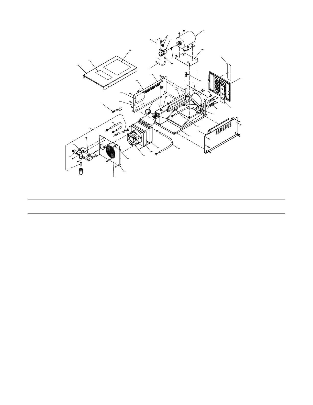
Figure 13-1. Complete Assembly
Description
Part
No.
Dia.
Mkgs.
Item
No.
Figure 13-1. Main Assembly
Quantity
1 230 156 Cover, top 1. . . . . . . . . . . . . . . . . . . . . . . . . . . . . . . . . . . . . . . . . . . . . . . . . . . . . . . . . . . . . . . . . . . . . . . .
2 +192 449 Label, warning/caution 1. . . . . . . . . . . . . . . . . . . . . . . . . . . . . . . . . . . . . . . . . . . . . . . . . . . . . . . . . . . . .
3 228 551 Plug, W/Leads Fan 1. . . . . . . . . . . . . . . . . . . . . . . . . . . . . . . . . . . . . . . . . . . . . . . . . . . . . . . . . . . . . . . . .
4 226 965 Panel, Side Rh 1. . . . . . . . . . . . . . . . . . . . . . . . . . . . . . . . . . . . . . . . . . . . . . . . . . . . . . . . . . . . . . . . . . . .
5 228 519 Hose, nprn brd no 1 X .250 ID X .455 OD X 9.000 1. . . . . . . . . . . . . . . . . . . . . . . . . . . . . . . . . . . . .
6 228 508 Pump, Coolant W/Fittings (Includes) 1. . . . . . . . . . . . . . . . . . . . . . . . . . . . . . . . . . . . . . . . . . . . . . . . . .
7 5523 Ftg, Hose Brs Barbed Elbow M 3/8 TBG X 3/8 NPT 2. . . . . . . . . . . . . . . . . . . . . . . . . . . . . . . . . . . . . . .
8 173 999 Pump, Coolant 100 Gph W/Clamps Cw Rotation 1. . . . . . . . . . . . . . . . . . . . . . . . . . . . . . . . . . . . . . .
9 134 795 Coupler, Drive Pump 1. . . . . . . . . . . . . . . . . . . . . . . . . . . . . . . . . . . . . . . . . . . . . . . . . . . . . . . . . . . . . . .
10 196 990 Ftg, Brs Barbed 1. . . . . . . . . . . . . . . . . . . . . . . . . . . . . . . . . . . . . . . . . . . . . . . . . . . . . . . . . . . . . . . . . . .
11 173 263 Motor, 1/4hp 115vac 50/60hz 1425/1725 Rpm Dual 1. . . . . . . . . . . . . . . . . . . . . . . . . . . . . . . . . . . . .
12 226 966 Bracket, Motor Mount 1. . . . . . . . . . . . . . . . . . . . . . . . . . . . . . . . . . . . . . . . . . . . . . . . . . . . . . . . . . . . . .
13 166 608 Cap, Tank Screwon W/Vent 1. . . . . . . . . . . . . . . . . . . . . . . . . . . . . . . . . . . . . . . . . . . . . . . . . . . . . . . .
14 226 932 Tank, Coolant 1. . . . . . . . . . . . . . . . . . . . . . . . . . . . . . . . . . . . . . . . . . . . . . . . . . . . . . . . . . . . . . . . . . . . .
15 228 529 Hose, .375 ID X .650 OD X 19.500 3. . . . . . . . . . . . . . . . . . . . . . . . . . . . . . . . . . . . . . . . . . . . . . . . . .
16 155 436 Label, Ground/Protective Earth 1. . . . . . . . . . . . . . . . . . . . . . . . . . . . . . . . . . . . . . . . . . . . . . . . . . . . . .
17 163 562 Light, Ind Wht Lens 125vac Snapin Neon Nonrelampa 1. . . . . . . . . . . . . . . . . . . . . . . . . . . . . . . .
18 231 308 Label, Rating Card CSA C US 300245 1. . . . . . . . . . . . . . . . . . . . . . . . . . . . . . . . . . . . . . . . . . . . . . . .
19 213 053 Panel, Louver Cover 1. . . . . . . . . . . . . . . . . . . . . . . . . . . . . . . . . . . . . . . . . . . . . . . . . . . . . . . . . . . . . . .
20 230 151 Plate, Indicator Front Cooler 1. . . . . . . . . . . . . . . . . . . . . . . . . . . . . . . . . . . . . . . . . . . . . . . . . . . . . . . . .
21 226 940 Valve, Check Bidirectional Assy 2. . . . . . . . . . . . . . . . . . . . . . . . . . . . . . . . . . . . . . . . . . . . . . . . . . . . . .
22 230 155 Backet, Valve Mounting 2. . . . . . . . . . . . . . . . . . . . . . . . . . . . . . . . . . . . . . . . . . . . . . . . . . . . . . . . . . . . .
23 226 964 Panel, Side Lh 1. . . . . . . . . . . . . . . . . . . . . . . . . . . . . . . . . . . . . . . . . . . . . . . . . . . . . . . . . . . . . . . . . . . . .
24 226 931 Base, Cooler 1. . . . . . . . . . . . . . . . . . . . . . . . . . . . . . . . . . . . . . . . . . . . . . . . . . . . . . . . . . . . . . . . . . . . . .
25 232 424 Radiator, Heat Exchanger 1. . . . . . . . . . . . . . . . . . . . . . . . . . . . . . . . . . . . . . . . . . . . . . . . . . . . . . . . . . .
26 226 922 Plenum, Air 1. . . . . . . . . . . . . . . . . . . . . . . . . . . . . . . . . . . . . . . . . . . . . . . . . . . . . . . . . . . . . . . . . . . . . . .
OM-231 313 Page 11
Description
Part
No.
Dia.
Mkgs.
Item
No.
Figure 13-1. Main Assembly (continued)
Quantity
27 213 072 Fan, Muffin 1. . . . . . . . . . . . . . . . . . . . . . . . . . . . . . . . . . . . . . . . . . . . . . . . . . . . . . . . . . . . . . . . . . . . . . . .
28 233 164 CABLE, Power 11 ft 4 in. 16 ga 3c 1. . . . . . . . . . . . . . . . . . . . . . . . . . . . . . . . . . . . . . . . . . . . . . . . . .
29 228 498 Panel, Rear 1. . . . . . . . . . . . . . . . . . . . . . . . . . . . . . . . . . . . . . . . . . . . . . . . . . . . . . . . . . . . . . . . . . . . . . .
30 196 312 Guard, Fan 1. . . . . . . . . . . . . . . . . . . . . . . . . . . . . . . . . . . . . . . . . . . . . . . . . . . . . . . . . . . . . . . . . . . . . . .
31 228 520 Filter, Assy W/Fittings (Includes) 1. . . . . . . . . . . . . . . . . . . . . . . . . . . . . . . . . . . . . . . . . . . . . . . . . . . . .
32 215 667 Filter 1. . . . . . . . . . . . . . . . . . . . . . . . . . . . . . . . . . . . . . . . . . . . . . . . . . . . . . . . . . . . . . . . . . . . . . . . . . . . .
33 228 532 Hose, .375 ID X .650 OD X 1.375 2. . . . . . . . . . . . . . . . . . . . . . . . . . . . . . . . . . . . . . . . . . . . . . . . . . .
34 231 311 Ftg, Hose Nyl Elbow Barbed 3/8 X 3/8 90 Deg 2. . . . . . . . . . . . . . . . . . . . . . . . . . . . . . . . . . . . . . . . .
35 226 967 Bracket, Mtg Filter 1. . . . . . . . . . . . . . . . . . . . . . . . . . . . . . . . . . . . . . . . . . . . . . . . . . . . . . . . . . . . . . . . . .
36 136 731 Hose, .375 ID X .650 OD X 10.500 1. . . . . . . . . . . . . . . . . . . . . . . . . . . . . . . . . . . . . . . . . . . . . . . . . .
37 228 530 Hose, .375 ID X .650 OD X 7.625 1. . . . . . . . . . . . . . . . . . . . . . . . . . . . . . . . . . . . . . . . . . . . . . . . . . .
38 231 368 Elbow/Tubing Assy, Return 1. . . . . . . . . . . . . . . . . . . . . . . . . . . . . . . . . . . . . . . . . . . . . . . . . . . . . . . . . .
39 231 367 Elbow/Tubing Assy, Pick-up 1. . . . . . . . . . . . . . . . . . . . . . . . . . . . . . . . . . . . . . . . . . . . . . . . . . . . . . . . .
40 231 284 Bushing, Tank Coolant 2. . . . . . . . . . . . . . . . . . . . . . . . . . . . . . . . . . . . . . . . . . . . . . . . . . . . . . . . . . . . . .
41 180 663 Label, Warning General Precautionary Static&wire Fe 1. . . . . . . . . . . . . . . . . . . . . . . . . . . . . . . . . .
42 178 910 Label, Caution Incorrect Coolant Wordless Intl 1. . . . . . . . . . . . . . . . . . . . . . . . . . . . . . . . . . . . . . . .
43 219 178 Label, Caution Incorrect Coolant 1. . . . . . . . . . . . . . . . . . . . . . . . . . . . . . . . . . . . . . . . . . . . . . . . . . . . .
+When ordering a component originally displaying a precautionary label, the label should also be ordered.
To maintain the factory original performance of your equipment, use only Manufacturer’s Suggested
Replacement Parts. Model and serial number required when ordering parts from your local distributor.
Notes
Work like a Pro!
Pros weld and cut
safely. Read the
safety rules at
the beginning
of this manual.
PRINTED IN USA © 2007 Miller Electric Mfg. Co.200701
Miller Electric Mfg. Co.
An Illinois Tool Works Company
1635 West Spencer Street
Appleton, WI 54914 USA
International HeadquartersUSA
USA Phone: 920-735-4505 Auto-Attended
USA & Canada FAX: 920-735-4134
International FAX: 920-735-4125
European Headquarters
United Kingdom
Phone: 44 (0) 1204-593493
FAX: 44 (0) 1204-598066
www.MillerWelds.com
Model Name Serial/Style Number
Purchase Date (Date which equipment was delivered to original customer.)
Distributor
Address
City
State Zip
Please complete and retain with your personal records.
Always provide Model Name and Serial/Style Number.
Contact a DISTRIBUTOR or SERVICE AGENCY near you.
Welding Supplies and Consumables
Options and Accessories
Personal Safety Equipment
Service and Repair
Replacement Parts
Training (Schools, Videos, Books)
Technical Manuals (Servicing Information
and Parts)
Circuit Diagrams
Welding Process Handbooks
Contact the Delivering Carrier to:
For Service
Owner’s Record
File a claim for loss or damage during
shipment.
For assistance in filing or settling claims, contact
your distributor and/or equipment manufacturer’s
Transportation Department.
Contact your Distributor for:
To locate a Distributor or Service Agency visit
www.millerwelds.com or call 1-800-4-A-Miller
1 / 1

Miller Coolmate 3.5 Owner's manual

Category
Welding System
Type
Owner's manual
This manual is also suitable for

Miller Coolmate 3.5 is a recirculating coolant system compatible with water-cooled GTAW torches and GMAW guns rated up to 600 amperes. With a 3.5-gallon coolant tank capacity and a maximum cooling capacity of 15,000 BTU/hr, it can maintain a steady coolant flow rate of 1.25 quart per minute.

Ask a question and I''ll find the answer in the document

Finding information in a document is now easier with AI

Ask the document