Page is loading ...

Product Manual
VS1-250
Copyright © 2009, Phoenix International. All rights reserved.
Publication number: VS1-250, Rev. B October 2009
Phoenix International and its logo are registered trademarks of Phoenix International, Inc. All
other trademarks or registered trademarks are the property of their respective owners. Phoenix
reserves the right change, without notice, product offerings or specifications.

Contents
1.0 Scope………………………………………………………………………....……1
2.0 Applicable standards and reference documentation…………………………..2
2.1
Standards
2.1.1 Electromagnetic compatibility
2.1.1.1 Electromagnetic susceptibility
2.1.2 European Union Restriction of Hazardous Substances (RoHS)
2.2 Reference documents
3.0 Description and specifications…………………………………………………...3
3.1 SAS / SATA connection via front panel connector
3.2 SAS / SATA connection via VME backplane
4.0 Configuration, installation and operation……………………………………..6
4.1 Handling and static-discharge precautions
4.2 Considerations for Installation
4.3 Installation
4.4 Drive Software Configuration
4.5 Operation
5.0 Drive Specification and Details………………………………………………..8
6.0 Product Support, Service and Warranty …………………………………...10
6.1 Warranty Statement
6.2 If You Have a Problem
6.3 Obtaining an RMA
6.4 Shipping the Product
6.5 Providing a Product Defect Report
6.6 Warranty Repairs
6.7 Non-warranty Repairs
6.8 Product Updates

1.0 Scope
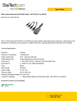
This manual describes the Phoenix International VS1-250 VME SAS/SATA storage module.
VS1-250 VME Data Storage Module with SAS HDDs
VS1-250 Product Manual Rev. B
- 1 -

2.0 Applicable Standards and Reference Documentation
The VS1-250 module has been developed to the highest standards of design and
construction. The module and storage device(s) depends on its host equipment to provide
adequate power and environment for optimum performance and compliance with applicable
industry and governmental regulations. Special attention should be given in the areas of
safety, power distribution, shielding, and temperature regulation.
2.2 Standards
The VS1-250 complies with the VME, SAS, and SATA specifications and standards as
noted in the appropriate sections of this manual.
2.1.1 Electromagnetic compatibility
The VS1-250 module with drive(s), as delivered, is designed for system integration and
installation into a suitable enclosure prior to use. The module is supplied as a subassembly
and is not subject to Subpart B of Part 15 of the FCC Rules and Regulations or the Radio
Interference Regulations of the Canadian Department of Communications.
The design characteristics of the module serve to minimize radiation when installed in an
enclosure that provides reasonable shielding. The module is capable of meeting the Class B
limits of the FCC Rules and Regulations of the Canadian Department of Communications
when properly packaged; however, it is the user’s responsibility to assure that the drive
meets the appropriate EMI requirements in their system. Shielded I/O cables may be
required if the enclosure does not provide adequate shielding. If the I/O cables are external
to the enclosure, shielded cables should be used, with the shields grounded to the
enclosure and to the host controller.
2.1.1.1 Electromagnetic susceptibility
As a component assembly, the VS1-250 is not required to meet any susceptibility
performance requirements. It is the responsibility of those integrating the module within their
systems to perform those tests required and design their system to ensure that equipment
operating in the same system as the module or external to the system does not adversely
affect the performance of the module and its disk drives.
2.1.2 European Union Restriction of Hazardous Substances (RoHS)
The European Union Restriction of Hazardous Substances (RoHS) Directive restricts the
presence of chemical substances, including Lead (Pb), in electronic products effective July
2006.
A number of parts and materials in Phoenix products are procured from external
suppliers. We rely on the representations of our suppliers regarding the presence of RoHS
substances in these parts and materials. Our supplier contracts require compliance with our
chemical substance restrictions, and our suppliers document their compliance with our
requirements by providing material content declarations for all parts and materials for the
module documented in this publication. Current supplier declarations include disclosure of
the inclusion of any RoHS-regulated substance in such parts or materials.
VS1-250 Product Manual Rev. B
- 2 -

2.2 Reference documents
ANSI/VITA1 VME64
SFF-8223 2.5” Drive Form Factor with Serial Connector
SFF-8460 HSS Backplane Design Guidelines
SFF-8470 Multi Lane Copper Connector
ANSI INCITS Serial Attached SCSI (SAS) Standard (T10/1601-D)
3.0 Description and Specifications
The VS1-250 is a rugged 6U, single slot, VMEbus mass storage plug-in module that houses
one or two 2.5” form factor Serial Attached SCSI (SAS) or Serial ATA (SATA) rotating hard
disk or solid state flash drives. It has been designed specifically to interface with VMEbus
processors with an embedded SAS or SATA Host Adapter. Together with the processor, a
complete system can be installed in only two standard VMEbus system slots. The VS1-250
can be configured for attachment to the SAS bus utilizing either the VME P2 connector or
the front panel SAS 4-lane external connector receptacle. Both attachment methods
provide contact for up to four physical links. A variety of SAS and SATA VME backplane P2
plug-in adapter cards are available from Phoenix International for host connection. There
are 2 Green light-piped LEDs visible at the front panel, one for each drive, which indicate
drive activity.
3.1 SAS / SATA Connection via Front Panel connector
For external host connection to the SAS bus via the front panel SAS receptacle use a high
quality cable assembly from your preferred cable manufacturer or contact Phoenix
International. This cable needs to have the SFF-8470 infiniband SAS external 4-lane plug
connector on the end mating to the front panel connector. The other end of the cable is
dependent upon your host adapter connection. Note that SAS can use cables up to 7.5 m
(25 ft) long while SATA is limited to 0.7 m (2.3 ft). Pin assignments for the front panel
receptacle, compliant with the ANSI INCITS SAS Standard (T10/1601-D), are as follows.
VS1-250 Product Manual Rev. B
- 3 -

Table 1 SFF-8470 SAS Front Panel Connector Pin Definitions
SIGNAL PIN
GND G1
Rx 0 + S1
Rx 0 - S2
GND G2
Rx 1 + S3
Rx 1 - S4
GND G3
Rx 2 + S5
Rx 2 - S6
GND G4
Rx 3 + S7
Rx 3 - S8
GND G5
Tx 3 - S9
Tx 3 + S10
GND G6
Tx 2 - S11
Tx 2 + S12
GND G7
Tx 1 - S13
Tx 1 + S14
GND G8
Tx 0 - S15
Tx 0 + S16
GND G9
VS1-250 Product Manual Rev. B
- 4 -

3.2 SAS / SATA Connection via VME Backplane
The VS1-250 can be configured for attachment to the SAS bus utilizing the VME P2
connector. An adapter card which plugs into the back of the VME backplane to connect to
the SAS bus and cables to the host is typically required for this configuration.
Contact Phoenix International for the type of adapter card and cable(s) required to meet
your needs. Pin assignments for the P2 VME connector are as follows.
Table 2 VME P2 Connector SAS/SATA and Adapter Card Pin Definitions
DRIVE VME P2 PIN SAS SIGNAL SATA SIGNAL SATA ADAPTER PIN
1 C1 GND GND J2-S7
1 C2 TP - Tx - J2-S5
1 C3 TP + Tx + J2-S6
1 C4 GND GND J2-S4
1 C5 RP + Rx + J2-S2
1 C6 RP - Rx - J2-S3
1 C7 GND GND J2-S1
1 C8 GND
1 C9 TS -
1 C10 TS +
1 C11 GND
1 C12 RS +
1 C13 RS -
1 C14 GND
2 C15 GND GND J1-S7
2 C16 TP - Tx - J1-S5
2 C17 TP + Tx + J1-S6
2 C18 GND GND J1-S4
2 C19 RP + Rx + J1-S2
2 C20 RP - Rx - J1-S3
2 C21 GND GND J1-S1
2 C22 GND
2 C23 TS -
2 C24 TS +
2 C25 GND
2 C26 RS +
2 C27 RS -
2 C28 GND
VS1-250 Product Manual Rev. B
- 5 -

4.0 Configuration, Installation, and Operation
4.1 Handling and static-discharge precautions
After unpacking, and before installation, the module may be exposed to potential handling
and electrostatic discharge (ESD) hazards. Observe the following standard handling and
static-discharge precautions:
Caution -
• Be sure you are properly grounded before handling the module. Put on a grounded wrist
strap, or ground yourself frequently by touching the metal chassis of a computer that is
plugged into a grounded outlet. Wear a grounded wrist strap throughout the entire
installation procedure.
• Handle the module by its edges or front panel only.
• Always rest the module on a padded, antistatic surface until you mount it in the enclosure.
• Do not touch the connector pins or any components on the printed circuit board.
4.2 Considerations For Installation
VMEbus Slot Requirements
The VS1-250 requires one slot in a standard VMEbus 6U card cage. Many drives have a
steel cover, which could potentially cause a shorting problem. If you are going to have a
VMEbus card located in the next adjacent slot, carefully check it to make sure that no leads
are likely to touch the top of the drives mounted on the VS1-250 module.
VMEbus Backplane Configuration
The VMEbus P1 connector supplies all operating power to the VS1-250 as well as ground.
No other signals are connected to the modules P1 connector. When configured for SAS to
VME backplane the SAS bus is connected via the P2 connector (see Table 2 for pin-outs).
Power Supply Requirements
Make sure that your VMEbus power supply has adequate capabilities to support the
operation of the drives mounted on the VS1-250 module while considering all other cards in
your VMEbus system. The specifications listed in Chapter 5 should be consulted for the
maximum current requirements. Your power supply must be capable of providing sufficient
current for the drive during initial operation.
4.3 Installation
VS1-250 Product Manual Rev. B
- 6 -

Assure that all power is removed from the VME backplane prior to inserting the VS1-250
module into the card cage. Align the VS1-250 module into its respective card cage slot card
guides and slide the module in until the P1 and P2 connectors initially mate. Apply pressure
to the ejector handles to fully seat the module / connectors.
Caution -
When seating the VS1-250 module into a card cage only apply pressure to the ejector
handles or, if necessary, to the base of the front panel. Applying pressure to the top of the
front panel could cause damage to the module.
Now connect the VS1-250 SAS bus to the host/processor with either (depending on
configuration) an SFF-8470 4-lane SAS cable to the front panel or via the P2 connector on
the backplane with the proper Phoenix International adapter module.
4.4 Drive Software Configuration
Initially you will need to run a device setup program in order to configure the software and
hardware to properly recognize the drives on the VS1-250. Consult the host/processor
manual and/or operating system manuals for a description of the utility required to properly
format and use your mass storage subsystem. The drive characteristics are described in
detail in Chapter 5. It operates using the SAS or SATA interface and has to be configured
by the host operating system software for proper operation.
4.5 Operation
Once the VL1-250 has been configured properly and the software has been set up,
operation is identical to that of a standard SAS / SATA storage subsystem. No specialized
software is required.
VS1-250 Product Manual Rev. B
- 7 -

5.0 Drive Specifications and Details
VS1-250 Product Manual Rev. B
- 8 -

VS1-250 Product Manual Rev. B
- 9 -

6.0 Product Support, Service and Warranty
This section describes Phoenix International’s product support program. It states our
product warranty and provides details about what to do if you have a problem with the
product.
6.1 Warranty Statement
Phoenix International VMEbus products come with a “return-to-factory” warranty which
covers defects in materials and workmanship for a period of two years from the date of
product shipment to the customer, provided the product is unmodified and has been subject
to normal and proper use. Warranty on non-Phoenix International manufactured devices
incorporated into Phoenix VMEbus products is restricted to that provided by their
manufacturer only.
6.2 If You Have a Problem
If you are having a problem with a Phoenix International product, call our main number,
(714) 283-4800, and ask for Customer Service. Please be prepared to supply as much detail
as you can concerning the nature of the problem and the conditions in which the problem
appeared.
6.3 Obtaining an RMA
In order to return the product for repair, the following steps are necessary:
1. Obtain a return materials authorization number (RMA#) from Phoenix International
Customer Service.
2. Ship the product prepaid to the designated repair point.
3. Provide a written description of the claimed defect with the product.
6.4 Shipping the Product
Any product returned to Phoenix International should be in its original shipping carton if
possible. Otherwise the product should be carefully packaged in a conductive packing
material and placed in a cushioned corrugated carton suitable for shipping.
Please mark the shipping label with the RMA number and return it to:
Phoenix International
812 W. Southern Avenue
Orange, CA., 92865
Attn: Customer Service Department
RMA #: ___________
VS1-250 Product Manual Rev. B
- 10 -

6.5 Providing a Product Defect Report
When returning a product for repair, it is very important to include a written report which
details the nature of the problem in order to expedite the repair. Please make sure that the
following information is included:
RMA # _________________
Product: _________________
Serial Number: ____________
Contact: _________________
Phone: _________________
Description of the problem/defect:
6.6 Warranty Repairs
Any product returned and found to be under warranty will be repaired or replaced at the
discretion of Phoenix International within ten working days of receipt and shipped freight
prepaid to the Customer.
6.7 Non-warranty Repairs
If a product is found not to be under warranty, we will notify you of the non-warranty situation
and provide you with a fixed cost and a schedule for the repair. Non-warranty repairs require
that a purchase order be issued to Phoenix International for the amount of the repair before
repairs are undertaken.
6.8 Product Updates
In an effort to improve product performance and reliability, Phoenix International reserves
the right to make product modifications provided they do not negatively impact either the
performance or operation of previous versions. If a product update is for the purpose of
correcting a design flaw, all customers shall be notified in writing as to the nature of the flaw
and the requirements for the update.
VS1-250 Product Manual Rev. B
- 11 -
/