Page is loading ...

Motorola LANPlanner Quick Start Guide - Page 1 of 15.
LANPlanner
LANPlannerLANPlanner
LANPlanner
11
1111
11.0
.0.0
.0
Quick Start Guide
Quick Start GuideQuick Start Guide
Quick Start Guide
Thank you purchasing LANPlanner. Please read the Quick Start Guide installation/upgrade
instructions prior
priorprior
prior to installing the software. Should you have any questions during this
installation/upgrade process, please feel free to contact us.
Motorola
Motorola Motorola
Motorola Wireless
WirelessWireless
Wireless Software
Software Software
Software Support
SupportSupport
Support
Phone:
Phone:Phone:
Phone: 1-800-653-5350
Email:
Email:Email:
Email: EMB[email protected]
Web:
Web:Web:
Web: mysymbolcare.symbol.com
Recommended Sy
Recommended SyRecommended Sy
Recommended System Requirements
stem Requirementsstem Requirements
stem Requirements
To effectively use this application, the following computer platform is recommended:
• Intel® Pentium® 4 1.5 GHz or better (or equivalent)
• Microsoft® Windows® XP (Professional, Home Edition and Tablet PC Edition) or Windows 2000
Professional
• Microsoft Word® XP (Word 2002) or later (required for generating Reports)
• 1 GB RAM
• 300 MB free disk space for installation
• 1024x768 VGA with true color
• Mouse, trackball or compatible pointing device with scroll wheel
• Microsoft Internet Explorer 6.0 or later
• CD-ROM drive
Support for Wireless Measurement via RF Monitoring Mode
Support for Wireless Measurement via RF Monitoring ModeSupport for Wireless Measurement via RF Monitoring Mode
Support for Wireless Measurement via RF Monitoring Mode
In order to enable data collection via RF Monitoring mode, you will need one of the WLAN client cards listed
below with LANPlanner’s custom driver installed. The supported cards are:
• Netgear® ProSafe Dual Band a/b/g Wireless PC Card, Model WAG511 v2
• Ubiquiti Networks SuperRange a/b/g Cardbus
• Cisco® a/b/g Cardbus Adapter, Model AIR-CB21AG-A-K9
• D-Link® RangeBooster N 650 b/g/n Notebook Adapter, Model DWA645
• CACE Technologies AirPcap N a/b/g/n Cardbus
• AirMagnet® C1060 a/b/g/n Cardbus Adapter

Motorola LANPlanner Quick Start Guide - Page 2 of 15.
Note about
Note about Note about
Note about Microsoft
MicrosoftMicrosoft
Microsoft Windows Vista
Windows Vista Windows Vista
Windows Vista®
®®
®:
::
: Currently, LANPlanner 11.0 is unsupported on Windows Vista. An
update to enable Windows Vista compatibility is being worked on for LANPlanner.
Install
InstallInstall
Installation
ation ation
ation on Win XP or Win 2000
on Win XP or Win 2000on Win XP or Win 2000
on Win XP or Win 2000
Installing LANPlanner is much like installing any other Microsoft Windows software. However, LANPlanner
uses electronic license control, so an extra activation step will be required. In order to install LANPlanner,
you will need your installation CD and some way to transfer files to your PC or receive email directly on your
PC.
Preparation
PreparationPreparation
Preparation
It is very important to perform the following preparatory steps to ensure your installation goes smoothly:
• Administrative Privileges
Administrative Privileges Administrative Privileges
Administrative Privileges Are
AreAre
Are
Required for Install:
Required for Install:Required for Install:
Required for Install: a user with local administrative privileges must
install LANPlanner. Non-administrative users may use the software once it has been installed.
• Internet Explorer
Internet Explorer Internet Explorer
Internet Explorer 6
66
6.0
.0.0
.0 or better
or betteror better
or better is required to properly run LANPlanner 11.0.
• Windows Servi
Windows ServiWindows Servi
Windows Service Packs:
ce Packs:ce Packs:
ce Packs: Your software will work best running with the most recent updates of
Windows 2000 or Windows XP. These upgrades are available through the Microsoft Windows Update
web site.
Installation procedure
Installation procedureInstallation procedure
Installation procedure
To install LANPlanner, please follow these steps in the order presented:
1. Close any programs running within Windows before starting the installation process.
2. Log on as ‘Administrator’ or as a user with administrative or power user privileges.
3. Insert the LANPlanner product CD into the CD drive.
4. If Autorun is activated on your computer, the setup program will start automatically. Otherwise, run
SETUP.EXE from the root folder on the product CD.
5. Read the warnings and the license agreement. You must accept the license agreement to continue.
6. Enter the user information, including your name, the name of your company and your serial number.
You will find the Software Serial number on either your printed manual or the face of the installation
CD (it is a 9-digit number in the form of xxx-xx-xxxx). If you downloaded the software through a
link provided by Motorola, please refer to the email containing the link for your serial number.
7. Choose the destination folder where the program files will be stored on the hard drive. We
recommend you accept the default folder name. If you choose a hard drive other than the default C:
drive, be sure to also type in a directory name; e.g. click on your D: drive and then type in \Program
Files\LANPlanner\.
8. Click Next to begin the installation process.
9. When setup is complete, you are ready to run the software by going to the Windows Start Menu and
selecting Programs > LANPlanner> LANPlanner.

Motorola LANPlanner Quick Start Guide - Page 3 of 15.
Hardware Removal
Hardware Removal Hardware Removal
Hardware Removal
IMPORTANT NOTE
IMPORTANT NOTEIMPORTANT NOTE
IMPORTANT NOTE:
: :
: You should only remove your WLAN card adapter from your computer using the
following hardware removal process. Failure to follow this process could cause your computer to crash and
loss of data.
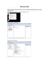
Step 1: First, close down or ensure that LANPlanner is not running
Step 2: Double click the Safe Hardware Removal icon in your system tray:
Step 3: Select your Wireless LAN Adapter from the Safely Remove Hardware dialog and choose Stop
Step 4: Again select your adapter and select Ok to confirm you wish to remove the hardware (Note, this will
not uninstall the driver. This process simply allows you to safely unplug the adapter from your computer)
Step 5: You may now remove the WLAN Adapter from your computer.
Custom
Custom Custom
Custom Driver Installation for the WLAN Client Card
Driver Installation for the WLAN Client CardDriver Installation for the WLAN Client Card
Driver Installation for the WLAN Client Card
In order to enable data collection via RF Monitoring mode, you will need one of the WLAN client cards listed
in the recommended system requirements with LANPlanner’s custom driver installed.
IMPORANT NOTE:
IMPORANT NOTE: IMPORANT NOTE:
IMPORANT NOTE: Do not install the card manufacturer’s driver. The installation of Motorola's custom
WLAN driver may not work correctly if the manufacturer’s driver has been previously installed on your
computer. If the manufacturer’s driver or other suitable driver has been previously installed on your
computer, please uninstall the client card before proceeding.
Step 1: Insert the network adapter into your computer’s PCMCIA slot.
Step 2: If the Hardware Update Wizard
Hardware Update WizardHardware Update Wizard
Hardware Update Wizard dialog window appears, choose Cancel
CancelCancel
Cancel.

Motorola LANPlanner Quick Start Guide - Page 4 of 15.
Step 3: Run the driver installer located in Help\WLAN Drivers located within your installation directory.
IMPORTANT:
IMPORTANT:IMPORTANT:
IMPORTANT:
For Cisco A/B/G Cardbus Adapter choose CiscoDriverSetup.exe.
For all other adapters choose DriverSetup.exe.
Step 4. Click Next
NextNext
Next to begin the driver installation process.
Step 5. You must accept the license agreement before installing the driver. If you accept the agreement,
check the radio button I accept this agreement
I accept this agreementI accept this agreement
I accept this agreement and click Next
NextNext
Next.

Motorola LANPlanner Quick Start Guide - Page 5 of 15.
Step 6. The wizard will begin searching for your new hardware.
If you receive a warning message saying that the software you are installing has not passed Windows Logo
testing, click Continue Anyw
Continue AnywContinue Anyw
Continue Anyway
ayay
ay

Motorola LANPlanner Quick Start Guide - Page 6 of 15.
Step 7. If the dialog indicates your hardware is ready to use, the installation was successful and the card is
now ready for use with RF Monitoring mode measurements.
If you encounter an error please contact Motorola’s wireless software support team at
EMB.support@motorola.com.
License activation
License activationLicense activation
License activation
Activation codes enforce your software license agreement. To obtain your new software license activation
software license activationsoftware license activation
software license activation,
please go to http://onepointwireless.com/rfdesign/activation.php
To obtain your license activation code, you will need to send ALL of the following pieces of:
To obtain your license activation code, you will need to send ALL of the following pieces of: To obtain your license activation code, you will need to send ALL of the following pieces of:
To obtain your license activation code, you will need to send ALL of the following pieces of:
Product Name
Product NameProduct Name
Product Name
The Product Name should be LANPlanner.
The three
The threeThe three
The three-
--
-d
dd
digit Product Version Number
igit Product Version Number igit Product Version Number
igit Product Version Number
The Product Version number can be found at the top of the About dialog box off of the main Help
menu in the software.
Serial Number
Serial NumberSerial Number
Serial Number
You will find the Software Serial number on either your printed manual or the face of the installation
CD (it is a 9-digit number in the form of xxx-xx-xxxx). If you downloaded the software through a
link provided by Motorola, please refer to the email containing the link for your serial number.
Client
Client Client
Client Lock Code
Lock Code Lock Code
Lock Code
Information for determining your product Client Lock Code is below.
When LANPlanner starts running, you will receive a message that “An activation code for your software
could not be obtained.” LANPlanner requires a valid activation code to run properly, though your install may
provide a short grace period in which partial functionality is available without registration.
When you click OK in the Activation Code Error dialog, you will reach the License Maintenance dialog.
To register the product, click the Register Product button.
The resulting Update License dialog displays a Client Lock Code field. The client lock code must be
provided to Motorola customer support, either by email or by phone. The client lock code does not change
for a particular PC, so if you Cancel out of the dialog and return later, you will have the same lock code.

Motorola LANPlanner Quick Start Guide - Page 7 of 15.
Motorola customer support will provide the necessary file containing the information LANPlanner
needs to activate (unlock) your license. The activation code file will be emailed to you. To use the file, place
it somewhere on your PC hard drive, and then use the Browse
BrowseBrowse
Browse button on the Update License
Update LicenseUpdate License
Update License dialog to
browse to the file and open it. When you have thus indicated the location of the activation code file, click
OK on the Update License dialog to activate your software. Barring any errors (e.g. the wrong file was
indicated or the file was somehow corrupted), you will now be able to use your software normally until the
expiration of your license.
In rare cases, you will be provided, either over the phone, via online chat or in email, a long
alphanumeric activation code that is not in a separate file on disk. To use such a code, simply type or copy
and paste it in the Enter Activation Code Manually
Enter Activation Code ManuallyEnter Activation Code Manually
Enter Activation Code Manually field. Your customer support agent will specify when the
Enter Activation Code Manually
Enter Activation Code ManuallyEnter Activation Code Manually
Enter Activation Code Manually field should be used. Ordinarily this field will not be used.
Please keep in mind that the electronic license control mechanism is merely an enforcement method
for the terms of the end user license. Regardless of the functions of the electronic license control, you are
bound by the terms of the software end user license agreement.
Multiple PC installation
Multiple PC installationMultiple PC installation
Multiple PC installation
According to the license agreement, your software can only be installed on one PC. License unlock codes
will not be provided for multiple PCs.

Motorola LANPlanner Quick Start Guide - Page 8 of 15.
What’s new in LAN
What’s new in LANWhat’s new in LAN
What’s new in LANPlanner
Planner Planner
Planner 11
1111
11.
..
.0
00
0?
??
?
• 802.11n Predictions and Measurements
802.11n Predictions and Measurements802.11n Predictions and Measurements
802.11n Predictions and Measurements:
: :
:
LANPlanner now has the ability to predict
and measure 802.11n performance for
new 802.11n hardware including the
Motorola AP-7131 Wireless Access Point.
• Multi
MultiMulti
Multi-
--
-Standard Predictions
Standard PredictionsStandard Predictions
Standard Predictions:
: :
: LANPlanner
can simultaneously visualize 802.11n and
legacy equipment performance within a
given environment.
• Enhanced Client Modeling and Predictions
Enhanced Client Modeling and PredictionsEnhanced Client Modeling and Predictions
Enhanced Client Modeling and Predictions:
::
:
Easily simulate multiple client
configurations and predict client to AP
performance.
• New Prediction and Measurement
New Prediction and Measurement New Prediction and Measurement
New Prediction and Measurement
Visualizations
VisualizationsVisualizations
Visualizations:
::
: Data rate delta is a new
prediction visualization which allows users
to easily see data rate improvements due
to infrastructure upgrades. New
measurement visualizations include
Hybrid Network Overlap, Data Rate
Performance, and Channel Width
Performance.
• Network Migration Wizard:
Network Migration Wizard:Network Migration Wizard:
Network Migration Wizard:
Easily view
results of upgrading current network
infrastructure using three common
upgrade scenarios: rip and replace -
convert all legacy equipment to new
802.11n equipment, mixed migration –
select areas requiring 802.11n coverage
while maintaining some legacy coverage,
and clean slate – create a new design
ignoring currently deployed equipment.
• Integration with Motorola’s RF
Integration with Motorola’s RF Integration with Motorola’s RF
Integration with Motorola’s RF
Management Suite:
Management Suite: Management Suite:
Management Suite: LANPlanner v11
includes the added functionality of
seamless integration with RF Management
Suite. Designs from LANPlanner can be
exported to RFMS for network
management. LANPlanner can also import
the live network status from RFMS,
enabling network engineers to adjust the
design of the modeled network based
upon the realities of the deployed
network. RFMS also includes the same RSSI
prediction capabilities found in
LANPlanner.
What’s new in LANPlanner 11.0.2?
What’s new in LANPlanner 11.0.2?What’s new in LANPlanner 11.0.2?
What’s new in LANPlanner 11.0.2?
• Enhancements
EnhancementsEnhancements
Enhancements
o Added AirDefense Sensors to install
o Added Sensors for AP5131 and AP7131
o Significantly improved response time
after recording a large group of markers
when using Track Run
Track RunTrack Run
Track Run mode
• Bug Fixes
Bug FixesBug Fixes
Bug Fixes
o Fixed crash where
RenamedEquipment.txt logfile
exponentially grew in size during
continued use.
o Fixed bug with RenamedEquipment.txt
logfile where names were not being
tracked properly between device types.
o Fixed errors with importing from RFMS
when the site name had multiple '.'
characters.

Motorola LANPlanner Quick Start Guide - Page 9 of 15.
What’s new in LANPlanner 11.0.3?
What’s new in LANPlanner 11.0.3?What’s new in LANPlanner 11.0.3?
What’s new in LANPlanner 11.0.3?
• Critical Fixes
Critical Fixes Critical Fixes
Critical Fixes
o Fixed issue where the software
could hang when generating a
report for predictions that included
only one contour for a given
visualization
o Fixed issue where the software
could crash when displaying
measurement heat-map
visualizations that included data
for channel 165
o Fixed issue where the software
could hang for a very specific
workflow which required running a
particular type of prediction
visualization after previously
viewing measurement heat-maps
during the same running instance
of the software
o Fixed issue where the software
could crash when exporting certain
component kits
• General Bug Fixes
General Bug Fixes General Bug Fixes
General Bug Fixes
o Fixed a backwards compatibility
issue where version 11.0.2 could
not previously open drawings
created in LANPlanner version
10.2.2. LANPlanner version 11.0.3
is now capable of reading drawings
produced in version 10.2.2
o Fixed an issue where the Motorola
WLAN cardbus driver would not
install onto non-English PCs
o Removed incorrect error messages
that appeared when deleting
access points that were previously
included in a utilization
visualization
o Fixed an issue where component
labels sometimes appeared on the
incorrect floor
o Fixed an issue where, for a small
subset of APs, transmit powers for
various air standards were getting
mixed up upon import from RFMS
3.x
What’s new in LANPlanner 11.0.4?
What’s new in LANPlanner 11.0.4?What’s new in LANPlanner 11.0.4?
What’s new in LANPlanner 11.0.4?
• General Bug Fixes
General Bug Fixes General Bug Fixes
General Bug Fixes
o Fixed an issue in the DAS editor
where the item selected in the air
standard combo box did not match
the data shown in the summary

Motorola LANPlanner Quick Start Guide - Page 10 of 15.
What’s new in
What’s new in What’s new in
What’s new in LAN
LANLAN
LANPlanner 11.0.5?
Planner 11.0.5?Planner 11.0.5?
Planner 11.0.5?
• General Bug Fixes
General Bug FixesGeneral Bug Fixes
General Bug Fixes
o Fixed a bug in leaky feeder cables
in which the cable loss remained
constant with respect to cable
length when the coupling loss was
too high

Motorola LANPlanner Quick Start Guide - Page 11 of 15.
Introduction to using
Introduction to using Introduction to using
Introduction to using LAN
LANLAN
LANPlanner
PlannerPlanner
Planner
Now that you have installed the software, you can
begin designing your wireless network. This
Quick Start Guide provides a summary of the
basic steps in formatting a building, so that you
can more easily complete your first project. You
can refer to the full LANPlanner User’s Guide for
detailed information about each step in the
process. The basic steps in executing a
LANPlanner project are:
• Create a 3D virtual model of your building
or campus: the “RF Intelligent Map”.
• Create a 3D virtual model of your wireless
network: the “RF Intelligent Model”.
• Simulate the behavior of your network, and
modify its design, until your performance
criteria are met.
• Document the design with a bill of materials
and full design report.
Modeling your building or campus
Modeling your building or campusModeling your building or campus
Modeling your building or campus
LANPlanner makes it easy to create a 3D virtual
model of your building environment. The 3D
model you will create consists of radio signal
propagation obstacles (e.g. walls) and includes
height, width, location and how much they
attenuate radio signals.
Your building model starts with a diagram
of the building floor plan. You can use a digital
scan of a paper floor plan (e.g. a fire escape plan
scanned into a digital picture format such as JPG,
BMP or GIF) or a CAD file created by an architect
or contractor. You can even draw a floor plan
freehand based on a verbal description of the
building. LANPlanner helps you convert a floor
plan into an RF Intelligent Map that contains
embedded radio propagation properties.
To create your 3D building model, use the
Building Wizard
Building WizardBuilding Wizard
Building Wizard (located in the Format Building
Format BuildingFormat Building
Format Building
menu). The Building Wizard will prompt you
through the creation of your building model.
Step-by-step instructions for using the Building
Wizard can be found in the User’s Guide. In
short, you will specify the number of floors in
your building, import a scanned image or CAD
floor plan for each floor, then use the tools in the
Building Wizard to trace or convert walls and
other radio signal obstacles. Each wall you trace
or convert will be classified into one of the
LANPlanner partition types, which has associated
radio signal attenuation properties. As you trace
or convert each wall from a CAD drawing, its
height is also assigned, creating a 3D model. You
will need to specify the scale of each floor of the
building (or of some part of it) and indicate a
point of alignment for stacking the floors. When
you are finished using the Building Wizard, click
Assemble Building
Assemble BuildingAssemble Building
Assemble Building to validate your selections and
finalize your building model.
Designing your network
Designing your networkDesigning your network
Designing your network
Now that you have a 3D virtual model of your
building (the RF Intelligent Map), you are ready to
create a 3D virtual model (The RF Intelligent
Model) of a wireless network. For wireless LAN
applications this could be something as simple as
a co-located antenna directly attached to an
Access Point or more sophisticated detached
antennas connected to the Access Points.
LANPlanner supports the modeling of these and
many other wireless network equipment types
that you may wish to deploy, including the 3D
routing of cables through your virtual building
model.
To install an Access Point in your building,
use the Network Design
Network DesignNetwork Design
Network Design > Pla
> Pla > Pla
> Place
ce ce
ce Access Point
Access PointAccess Point
Access Point
menu command. Double-click on the Access
Point in the ‘Place Access Point’
‘Place Access Point’ ‘Place Access Point’
‘Place Access Point’ dialog window

Motorola LANPlanner Quick Start Guide - Page 12 of 15.
that supports your desired standards. Click in the
drawing to indicate the location of your Access
Point. You can continue clicking in the drawing if
you wish to add more than one Access point.
Once you have placed the desired number of
Access points, simply right click or press the Esc
button. Click Done
DoneDone
Done to exit the ‘Place Access
‘Place Access ‘Place Access
‘Place Access
Point’
Point’Point’
Point’
dialog box. To edit properties of your
Access Points, you can go to Network Design >
Network Design > Network Design >
Network Design >
Edit/Remove Access Point
Edit/Remove Access PointEdit/Remove Access Point
Edit/Remove Access Point, highlight an Access
point and click E
EE
Edit
ditdit
dit. The ‘Edit Access Point’
‘Edit Access Point’‘Edit Access Point’
‘Edit Access Point’
dialog provides fields for specifying the transmit
power, air interface standard, channel, frequency
and other characteristics. You can click the
Distribution System Editor
Distribution System EditorDistribution System Editor
Distribution System Editor button in the Edit
Edit Edit
Edit
Virtual Source
Virtual Source Virtual Source
Virtual Source dialog to add cabling, antennas,
and other components to your network. In the
resulting Distributed Antenna System
Distributed Antenna System Distributed Antenna System
Distributed Antenna System dialog, click
the Add
Add Add
Add button to add parts to your network. If
you add a cable, you will need to route the cable
by clicking in the drawing to indicate its path
through the building (right click or hit the Escape
key to stop routing cable). If you choose to add
an antenna, you’ll be able to view the radiation
pattern for each antenna in the list of
specifications provided with LANPlanner. You can
also install connectors, splitters, amplifiers, and
other components.
When you click OK
OKOK
OK to exit the Distributed
Distributed Distributed
Distributed
Antenna System
Antenna SystemAntenna System
Antenna System editor dialog, and OK
OKOK
OK again to
exit the Edit
Edit Edit
Edit Access Poi
Access PoiAccess Poi
Access Point
ntnt
nt dialog, you’ll complete
the process of installing a virtual Access Point and
its associated distribution system in your building
model.
Visualizing network performance
Visualizing network performanceVisualizing network performance
Visualizing network performance
Now that you have equipment placed in your RF
Intelligent Model, you can simulate and visualize
its expected performance. Select the Network
Network Network
Network
Design
DesignDesign
Design >
> >
> Quick Predict
Quick PredictQuick Predict
Quick Predict menu command to access
the Quick Predict
Quick PredictQuick Predict
Quick Predict Dialog Box
Dialog Box Dialog Box
Dialog Box. Select Grid
Grid Grid
Grid
Predictions
PredictionsPredictions
Predictions
and click Configure
ConfigureConfigure
Configure to adjust the grid
parameters. Select the Air Interface Standards
Air Interface Standards Air Interface Standards
Air Interface Standards
you wish to model and choose between Forward
Forward Forward
Forward
and Reverse Links.
Reverse Links.Reverse Links.
Reverse Links. Press Next.
Next.Next.
Next. Highlight the
Access Point(s) you wish to predict for and then
click OK. Wait for the software to calculate the
simulation results – it shouldn’t be a long wait.
The result will be a sheet or grid of colored
squares draped over your building walls. The
color and height of the squares indicates the
received signal power at that point in the
building. You can hover your mouse pointer over
the grid edges to get a tooltip reading of the
signal strength.
To improve the appearance of the
simulation results, choose the View > Shade >
View > Shade > View > Shade >
View > Shade >
Flat Shaded, Edges On
Flat Shaded, Edges OnFlat Shaded, Edges On
Flat Shaded, Edges On menu command, or the
View > 3D Views > SW Isometric
View > 3D Views > SW IsometricView > 3D Views > SW Isometric
View > 3D Views > SW Isometric menu command.
Now you can visualize how RF will travel in your
deployment environment.
For a detailed list of the equipment, cabling
and antennas used in your network design plan,
use the Utilities > Display Bill of Materials
Utilities > Display Bill of MaterialsUtilities > Display Bill of Materials
Utilities > Display Bill of Materials menu
command to list the equipment you used.
To use the Reporting feature, go to Utilities
UtilitiesUtilities
Utilities
> Reports
> Reports> Reports
> Reports. In the Report Configuration
Report ConfigurationReport Configuration
Report Configuration dialog
window, you see several tabs. Under the Project
Project Project
Project
Overview
OverviewOverview
Overview tab, you can add information about the
design project. Next, the Design Summary
Design SummaryDesign Summary
Design Summary tab
allows you to choose what types of information
you wish to include regarding the Access
Points. Select the options you wish to have
displayed in your report. Finally, under the
Predictions
PredictionsPredictions
Predictions tab, you can choose the Air Interface
Air Interface Air Interface
Air Interface
Standard
StandardStandard
Standard and the type of simulations you wish to
have included. Choose at least one of the
standards under the Air interface
standards. Under Contour Simulations, select
‘Include contour simulations’
‘Include contour simulations’‘Include contour simulations’
‘Include contour simulations’ and ‘Power
Power Power
Power
(RSSI)
(RSSI)(RSSI)
(RSSI).’ Under Grid Simulations, select ‘Include
Include Include
Include
Grid Simulations
Grid SimulationsGrid Simulations
Grid Simulations’ and Power (non
Power (nonPower (non
Power (non-
--
-composite
composite composite
composite
RSSI)
RSSI)RSSI)
RSSI). Click the Generate Report
Generate ReportGenerate Report
Generate Report button. A Save
As window will pop up. Choose an appropriate
location for saving the report and make sure to
enter a file name. Click Save
SaveSave
Save and wait as the

Motorola LANPlanner Quick Start Guide - Page 13 of 15.
reports are generated. When the Report has been
generated, a prompt will notify you. You can then
open up the Report using Microsoft Word from
the location where you saved it.

Motorola LANPlanner Quick Start Guide - Page 14 of 15.
Known
Known Known
Known Issues
IssuesIssues
Issues
Related to
Related to Related to
Related to LAN
LANLAN
LANPlanner
Planner Planner
Planner 11
1111
11.
..
.0
00
0
• Compatibility with previous
Compatibility with previous Compatibility with previous
Compatibility with previous Motorola
MotorolaMotorola
Motorola PC
PC PC
PC-
--
-based
based based
based
software versions:
software versions: software versions:
software versions: LANPlanner 11.0 is
backwards compatible with drawings created in
LANPlanner 10.x. However, grid predictions
created in LANPlanner 10.x will not be correctly
colored in LANPlanner 11.0. All grid predictions
previously calculated using LANPlanner 10.x
must be recalculated and redisplayed in
LANPlanner 11.0. Note that LANPlanner 10.x
cannot open drawings created with version
11.0 or higher.
• LANPlanner 11.0 comes with new default color
schemes that increase the maximum data rate
visible in performance visualizations to values
that coincide with the 802.11n standard. To
visualize the new data rates of 802.11n without
additional modification, these new color
schemes will need to be loaded manually for
existing drawings created before version 11.0
(or EnterprisePlanner 11.0/ SiteScanner
2.0). To load the new color schemes:
1. Open your drawing
2. Select Uti
UtiUti
Utilities
litieslities
lities-
--
->Edit Color Schemes...
>Edit Color Schemes...>Edit Color Schemes...
>Edit Color Schemes...
from the menu
3. Click the Load From File
Load From FileLoad From File
Load From File button at the
bottom of the Edit Colors
Edit ColorsEdit Colors
Edit Colors dialog
4. Open the C:
C:C:
C:\
\\
\Program
Program Program
Program
Files
FilesFiles
Files\
\\
\LAN
LANLAN
LANPlanner
PlannerPlanner
Planner\
\\
\BOM
BOMBOM
BOM\
\\
\colors.xml
colors.xmlcolors.xml
colors.xml file
to load the new default color schemes
into your drawing
• When visualizing 802.11n performance for
40MHz channels it may be necessary to
configure the color scheme for your
visualization to include higher data rates than
the default 130Mbps. A suggested scheme has
already been provided for this. To assign the
Peak Data Rate (up to 300
Peak Data Rate (up to 300Peak Data Rate (up to 300
Peak Data Rate (up to 300Mbps)
Mbps)Mbps)
Mbps) scheme:
1. Open your drawing
2. Select Utilities
UtilitiesUtilities
Utilities-
--
->Edit Color Schemes...
>Edit Color Schemes...>Edit Color Schemes...
>Edit Color Schemes...
from the menu
3. Select the data rate display type you
would like to change from the Color
Color Color
Color
Scheme Assignment
Scheme AssignmentScheme Assignment
Scheme Assignment list (Contour Data
Rate, Grid Data Rate, etc.)
4. Click the Edit
EditEdit
Edit button in the Color
Color Color
Color
Scheme Assignment
Scheme AssignmentScheme Assignment
Scheme Assignment section of the
dialog
5. Select the Peak Data Rate (up to
Peak Data Rate (up to Peak Data Rate (up to
Peak Data Rate (up to
300Mbps)
300Mbps)300Mbps)
300Mbps) color scheme
• Some Optimatic features may on occasion
become disabled after visualizing
measurement heat-maps. Work-a-round:
Select another menu item prior to selecting an
optimization menu item (e.g. Record
Measurements). The software will then
function as intended.
• Conflict with TrendMicro firewall:
Conflict with TrendMicro firewall:Conflict with TrendMicro firewall:
Conflict with TrendMicro firewall: TrendMicro
firewall must be disabled before taking
measurements in RF Monitoring mode with the
custom driver to avoid possible system
crashes. The following steps can be taken to
disable the firewall:
1. Go to Start -> Run -> services.msc
2. Double click the service named
OfficeScanNT Personal firewall
OfficeScanNT Personal firewallOfficeScanNT Personal firewall
OfficeScanNT Personal firewall
3. In the dialog that appears change the
Startup type
Startup typeStartup type
Startup type to Disabled
DisabledDisabled
Disabled, press Stop
StopStop
Stop and
click Ok
OkOk
Ok
4. Go to Start -> Control Panel -> Network
Connections
5. Right click the Motorola measurements
adapter and select Properties
PropertiesProperties
Properties
6. In the dialog that appears uncheck the
Trend Micro Common Firewall Driver
Trend Micro Common Firewall DriverTrend Micro Common Firewall Driver
Trend Micro Common Firewall Driver in the
list of available network components and
press OK
OKOK
OK

Motorola LANPlanner Quick Start Guide - Page 15 of 15.
Motorola
Motorola Motorola
Motorola Wireless Software
Wireless Software Wireless Software
Wireless Software Support
SupportSupport
Support
Phone:
Phone:Phone:
Phone: 1-800-653-5350
Email:
Email:Email:
Email: EMB[email protected]
Web:
Web:Web:
Web: mysymbolcare.symbol.com
/