Page is loading ...

^
AF
Installation
GRAA-IOM-1
Operation
Maintenance
Library
Service
Literature
P
roduct
Sec
t
ion
Air
Handling
Product
Make
-
Up
Air
Model
GRAA
,
GRBA
,
GRCA
,
GRDA
Literature
T
ype
I
nstallation
,
Operation
,
Maintenance
Sequence
^
Date
January
1995
File
No.
SV
-
AH
-
MUA
-
GRAA
-
IOM
-
1
-
1
95
Supersedes
Ne
w
Rooftop
Gas
Heating
,
Cooling
and
Ventilating
Unit
Sizes
100
MBh
-
1200
MBh
"
A
"
Design
Sequence
Since
the
Trans
Company
has
a
policy
of
continuous
product
improvement,
it
reserves
the
right
to
change
specifications
and
design
without
notice.
The
installation
and
servicing
of
the
equipment
referred
to
in
this
booklet
should
be
done
by
qualified,
experienced
technicians.
OAmerican
Standard
Company
1995

General
Information
Literature
Chang
e
History
GRAA
-
IOM
-
1
(January
1995
)
Original
issue
of
manual
describes
installation
of
GRAA,
GRBA,
GRCA,
GRDA
Rooftop
Gas
Heating,
Cooling
and
Ventilating
Units,
for
A
Design.
Warnings
and
Cautions
Notice
that
WARNINGS
and
CAUTIONS
appear
at
appropriate
intervals
throughout
this
manual.
Warnings
alert
installer,
owner,
operator
or
service
personnel
to
potential
hazards
that
could
result
in
personal
injury
or
death.
Cautions
are
provided
to
alert
personnel
to
conditions
which
could
result
in
damage
to
the
equipment
or
cause
property
damage.
Receiving
Instructions
Inspect
shipment
immediately
when
received
to
determine
if
any
damage
has
occurred
to
the
unit
during
shipment.
After
the
unit
has
been
uncrated,
check
for
any
visible
damage
to
the
unit.
If
any
damage
is
found,
the
consignee
should
sign
the
bill
of
lading
indicating
such
damage
and
immediately
file
claim
for
damage
with
the
transportation
company.
FOR
YOUR
SAFETY
:
If
you
smell
gas
:
1
.
Open
windows
.
2
.
Don
'
t
touch
electrical
switches
.
3
.
Extinguish
any
open
flame
.
4
.
Immediately
call
your
gas
supplier
.
FOR
YOUR
SAFETY:
The
use
and
storage
of
gasoline
or
other
flammable
vapors
and
liquids
in
open
containers
in
the
'
vicinity
of
this
appliance
is
hazardous.
WARNING:
Improper
installation,
adjustment,
alteration,
service
or
maintenance
can
cause
property
damage,
injury
or
death.
Read
the
installation,
operating
and
maintenance
instructions
thoroughly
before
installing
or
servicing
this
equipment.
Warnings
Approved
for
use
in
California
when
equipped
with
spark
ignition
.
Installer
Please
Note:
This
equipment
has
been
test
fired
and
inspected
.
It
has
been
shipped
free
from
defects
from
our
factory
.
However
,
during
shipment
and
instal
l
ation
,
problems
such
as
loose
wires,
leaks
or
loose
fasteners
may
occur.
It
is
the
installer
'
s
responsibility
to
inspect
and
correct
any
problems
th
a
t
may
be
found
.
Install,
operate
and
maintain
unit
in
accordance
with
manufacturer's
instructions
to
avoid
exposure
to
.,
fiP
P
R
OYED
fuel
substances
or
substances
from
incomplete
combustion
which
can
cause
death
or
serious
illness.
The
state
of
California
has
determined
that
these
substances
may
cause
cancer,
birth
defects,
or
other
reproductive
harm.

Model
Number
Description
(All
furnaces)
DIGIT
1
-
Gas
Heating
Equipment
G
=
G
as
DIGIT
2
-
Unit
Type
F =
Rooftop
D
uct
Furnace
R
=
R
oofto
p
H
eating
U
ni
t
S
=
Special
U
ni
t
T
y
p
e
DIGIT
3
-
Furnace
Type
A
=
S
t
a
ndard
T
e
m
p
R
ise
(
20
-6
0
D
eg.
F
)
LH
B
=
S
tandard
Te
m
p
R
ise
(
2
0-
60
Deg
.
F
)
RH
C
=
High
Temp
Rise
(60-90
Deg.
F)
LH
D
=
High
Tem
p
R
is
e
(60-90
De
g.
F
)
RH
E
=
B
lank
F
urnac e
S
l
ee
v
e
LH
G
= Blank
Furnace
Sleeve
RH
S
=
Special
Furnace
Type
DIGIT
4
-
Development
Sequence
A
=
F
irs
t
G
eneratio
n
DIGIT
5,6
-
Input
Capacity
Single
Furnace
10
=
100
MBh
Input
30
=
300
MBh
Input
15
=
150
MBh
Input
35
=
350
MBh
Input
20
=
200
MBh
Input
40
=
400
MBh
Input
25
=
250
MBh
x
Double Furnace
50
=
500
MBh
Input
70
=
700
MBh
Input
60
=
600
MBh
Input
80
=
800
MBh
Input
Triple
Furnace
12
=
1200
MBh
Input
SS
=Special
unit
DIGIT
7
-
Venting
Type
G
=
G
ravi
t
y
V
e
n
ting
P
=
P
ower
Ventin g
S
=
S
pecial
V
enting
DIGIT
9
-
Gas
Control
Option
(Intermittent
Pilot
Ignition)
A
=
Single-Stage
B
=
Two-Stage
C
=
Hydraulic
Modulating
(60-100)
D
=
Hydraulic
Modulating
(75-200)
E
=
Hydraulic
Modulating
W/Bypass
and
limit
(60-100)
F
=
Hydraulic
Modulating
W/Bypass
(75-200)
G
=
Electronic
Modulating
W/Room
T-Stat
H
=
Electronic
Modulating
W/Duct
T-Stat
J
=
Electronic
Modulating
W/Duct
T-Stat
and
Override
Room
Thermostat
K=
Electronic
Modulating
W/External
4-20
mA
Input
(Furnace
1)
L =
Electronic
Modulating
W/External
4-20
mA
Input
M=
Electronic
Modulating
W/External
0-10
VDC
Input
(Furnace
1)
N
=
Electronic
modulating
W/External
0-10
VDC
Input
P
=
VAV
Control
Two-Stage
R=
VAV
Control
Three-Stage
T
=
VAV
Control
Four-Stage
U
=
S-350
2
Stage
Modular
Electronic
Control
System
W
=
S-350
3
Stage Modular
Electronic
Control
System
X
=
S-350
4
Stage
Modular
Electronic
Control
System
Y
=
S-350
6
Stage
Modular
Electronic
Control
System
S
=Special
Gas
Control
DIGIT
13
-
Heat
Exchanger
Material
1
= Aluminized
S
teel
2
=
#
409
St
ainless
S
teel
(
F
i
r
s
t
Furn
a
ce
Only)
3
=
#409
Stainless
Steel
(All
Furnace
Sections)
4
=
#
3
21
S
t
a
inless
S
t
e
el
(
F
irst
F
ur
n
ac
e
O
nly)
5
=
#3
21 St
ainless
S
teel
(
A
ll
F
ur
na
ce
Sections)
6
=
#
4
09
S
tainless
S
teel
P
ackag
e
(
F
ir
s
t
Furnace
Only)
7
=
#409
S
tainless
St
eel
P
acka
ge
(
A
ll
F
urnace
S
ections)
8
=
#32
1
S
tainless
S
teel
P
acka
g
e(
F
irs
t
Furnace
Only)
9
=
#321
Stainless
Steel
P
acka
g
e(
A
ll
F
urnace
S
ec
t
ions)
S
=
Special
Heat
Exchanger
P
ackage
DIGIT
14
-
Rooftop
Arrangements
(Des
i
gnator
A
-
L
Assumes
Furnace
S
ecti
on
)
A
=
D
uct
Furnace
B
=
B
lower
(
S
tandard)
C
=
Blower
(Standard)
Plenum
D
=
B
lower
(Standard)
E
vaporative
C
oole
r
E
=
Blower
(Standard)
E
vaporativ
e
C
ooler/Plenum
G
=Blower
(High
CFM)
J
=
B
lower
(
H
igh
C
F
M
)/Plenum
K
=
B
lower
(
H
igh
C
F
M
)/
C
oolin
g
L
=
B
lower
(
H
igh
C
F
M
)/
C
o
o
lin
g
/
P
le
n
u
m
S
=
S
pecial
R
oofto
p
A
rr
a
ng
m
ent
DIGIT
8
-
Main
Power
Supply
A
=
115/60/1
E
=
230/60/3
B
=
208/60/1
F
=
460/60/3
C
=
230/60/1
G
=
575/60/3
D
=
208/60/3
S
=
Special
Main
Power
Supply
DIGIT
10
-
Design
Sequence
A
=
F
irst
D
esi
gn
DIGIT
11
-Design
Sequence
0
=
F
irst
D
esign
DIGIT
12
-
Fuel
Type
N
=
N
atural
Ga
s
P
=
LP
G
as
(
P
ropane)
L
=
N
a
t
ural
G
as
with
1
00%
L
ockout
S
=
S
pecial
F
uel
type
DIGIT
15
=
Roo
fto
p
H
eati
ng
Un
i
t
Motor
Selection
0
=
N
one
(Rooftop duct
furnace)
A
=
1/2
HP
w/contactor
B
=
3/4
HP
w/contactor
C
=
1
HP
w/contactor
D
=
1
1/2
HP
w/contactor
E
=
2
HP
w/contactor
F
=
3
HP
w/contactor
G
=
5
HP
w/contactor
H
=
1/2
HP
w/magnetic
starter
J
=
3/4
HP
w/magnetic
starter
K
=
1
HP
w/magnetic
starter
L
=
1
1/2
HP
w/magnetic
starter
N
=
2
HP
w/magnetic
starter
P
=
3
HP
w/magnetic
starter
Q
=
5
HP
w/magnetic
starter
R
=
7
1/2
HP
w/magnetic
starter
T
=
10
HP
w/magnetic
starter
U
=
15
HP
w/magnetic
starter
S
=
Special
Motor
1a

DIGIT
16
=
Motor
Speed
0
=
N
o
Selection
1
=
Single
Speed
ODP
1
800
RPM
2
=
Single
Speed
T
EF
C
180
0
R
PM
3
=Single
S
peed
H
igh
E
fficiency
ODP
1800
RPM
4
=
S
ingle
S
p
eed
H
igh
E
fficie
n
c
y
TEFC
1800
RPM
5
=
2S1
W
ODP
1800/900
RPM
6
=
2S2W
ODP
1800/1200
RPM
7
=
Special
M
o
t
o
r
Spee
d
&
S
tarter
DIGIT
17
=
Coil
Options
0
=
N
o
cooling
coil
selection
A
=
DX
coil,
4
R
ow,
Single
C
ircuit
B
=
DX
coil,
4
R
ow,
D
ual
C
ircui
t
C
=
DX
coil,
6
R
ow,
S
ingle
Circuit
D
=
DX
coil,
6
R
ow,
D
ual
C
ircuit
E
=
Chilled
W
ater
C
oil,
4
R
ow,
G
=
Chilled
Wa
t
er
Co
il,
6
R
ow,
S
=
Special
coil
DIGIT
18
=
Air
Inlet
Configuration
0
=
N
one
(
R
ooftop
duct
furnace)
1
=
Outside
Air(
OA
)
2
=
Outside
A
ir
W
/
A
ir
H
ood
3
=
R
etur
n
Air(
R
A)
4
=
Outside
An
d
R
eturn
A
ir
(
OA
/
RA
)
5
=
Outside
and
R
e
t
urn
Air
W
/
A
ir
H
ood
S
=
Special
A
ir
inlet
configu
r
a
t
io
n
DIGIT
19
=
Air
Control
& Damper
Arrangement
0
=
N
one
(
R
ooftop
duct
f
urnace)
A
=
O
u
t
side
Air
2
pos.
M
otor/
SR
B
=
R
eturn
Air
2
pos.
Mo
tor/
SR
C
=
OA
/
RA
2
p
os
S
R
D
=
OA
/
RA
M
o
d
M
i
r
.
W
/
M
ixe
d
A
ir
C
on
t
rol/
M
in.
P
o
t
E
=
O
A/
R
A
M
od
M
tr
W
/
M
ixe
d
A
ir
Control/Min
Pot/SR
G
=
OA
/
RA
M
od
Mi
r
W
/
M
ixed
A
ir
Co
ntr
o
l
H
=
O
A
/
RA
Mod
Mtr
W/Mixed
Air
Control/
SR
J
=
O
A/
RA
M
od
M
tr
W
/
M
i
n
P
o
t
K
=
OA/RA
Mod
Mtr
W/Min
P
ot/SR
L =
O
A
/
RA
M
od
Mtr
w
/
D
ry
B
ulb/
M
ixe
d
A
ir
C
o
n
trol/
M
in
P
ot
M
=
O
A/
RA
M
od
M
tr
w/
D
ry
B
ulb/
M
ixe
d
A
ir
C
ontrol/
M
in
P
ot/S
R
N
=
OA
/
R
A
M
od
Mi
r
w/
E
nthalpy
Co
n
trolled
E
conomizer/
SR
P
=
OA
/
RA
M
o d
M
tr
W
/
S
p
ac e
P
re
ss
ur
e
Controller
R
=
OA
/
RA
M
od
M
tr
W
/
S
-35
0
P
Proportional
Mixed
Air
Control/SR
T
=
OA
/
RA
M
tr.
W
/External
0-
10
VDC
a
nd
4
-
20
m
AAn
alog
Inpu
t
/(
Ex
tern
a
l
In
pu
t)
U
=
OA
/
RA
M
tr.
W
/Exter
na
l
0
-
10
VDC
a
n
d
4
-
2
0
m
A
A
nalog
I
npu
t
/
SR
(
Exte
rnal
I
npu
t )
W
=
A
shrae
C
ycle
I
(
OA
/
RA
2
p
os,
w/warm-u
p
stat/
SR
X
=
Ashrae
C
ycle
I
I
(
OA
/
RA
M
o
d
W
/
W
arm-up
S
ta
t
/
M
ixe
d
A
ir/min
pot/S
R
Y
=
Ashrae
C
ycle
111(
O
A/RA
M
o
d
.
W/Warm-up
St
at/
M
ixed
Air/
SR
Z
=
M
anual
D
ampe
r
s
S
=
S
pecial
air
control
a
n
d
dam
p
er
a
r
r
ange
m
e
n
t
DIGIT
20
0
=
N
o
n
-
C
ali
fo
rnia
S
hi
pm
ent
1
=
California
Shipment
DIGIT
21
=
Miscellaneous
Options
A
=
O
rifice
s
For
E
lev
at
io
n
A
bov
e 2
000
F
e
et
(
S
pe
c
i
f
y
E
l
e
v a
ti
o
n)
B
=
1
2"
E
va
p
or
a
tive
M
e
d
i
a
C
=
M
ois
t
ure
E
limin at
ors
D
=
H
ori
zonta
l
R
eturn
E
=
I
nterlock
R
elay
-2
4V
C
oil
DPD
T
1
0
A
F
=
Fr
e
e
ze
s
t
at
G
=
Fa
n
T
i
m
e
D
elay
C
on
tr
ol
(
D
uc
t
F
urnac
e
Only)
H
=
R
etu
r
n
A
ir
Fir
e
sta
t
J= Supply
Air
Firestat
K
=
M
anual
B
lower
S
wi
t
ch
L
= 4
09
S
tainle
ss
S
teel
Furnace
D
rip
Pa
n
N
=
F
oil
F
ace
I
nsulation
P
=
Lo
w
Le
ak
Da
mpers
Q
=
C
logg
ed
Filter
S
witch
R
=
H
ig
h /L
ow
G
a
s
P
ress
u
re
L
i
m
i
t
S
wi
t
c
h
e
s
T
=
St
a
t
us
Indicat
o
r
La
m
ps
(
E
lec
cab
ine
t
)
V
=
Manu
al
Res
et
H
i
g
h
L
imi
t
Sw
i
tc
h
W
=Interl
o
ck
Re
lay
-
2
4/
1
15
V
Co
il
SPDT
10A
X
=
I
nt
e
rloc
k
R
elay
-
24
/1
1
5-
2
3
0V
Co
il
DPDT
1
0A
lb
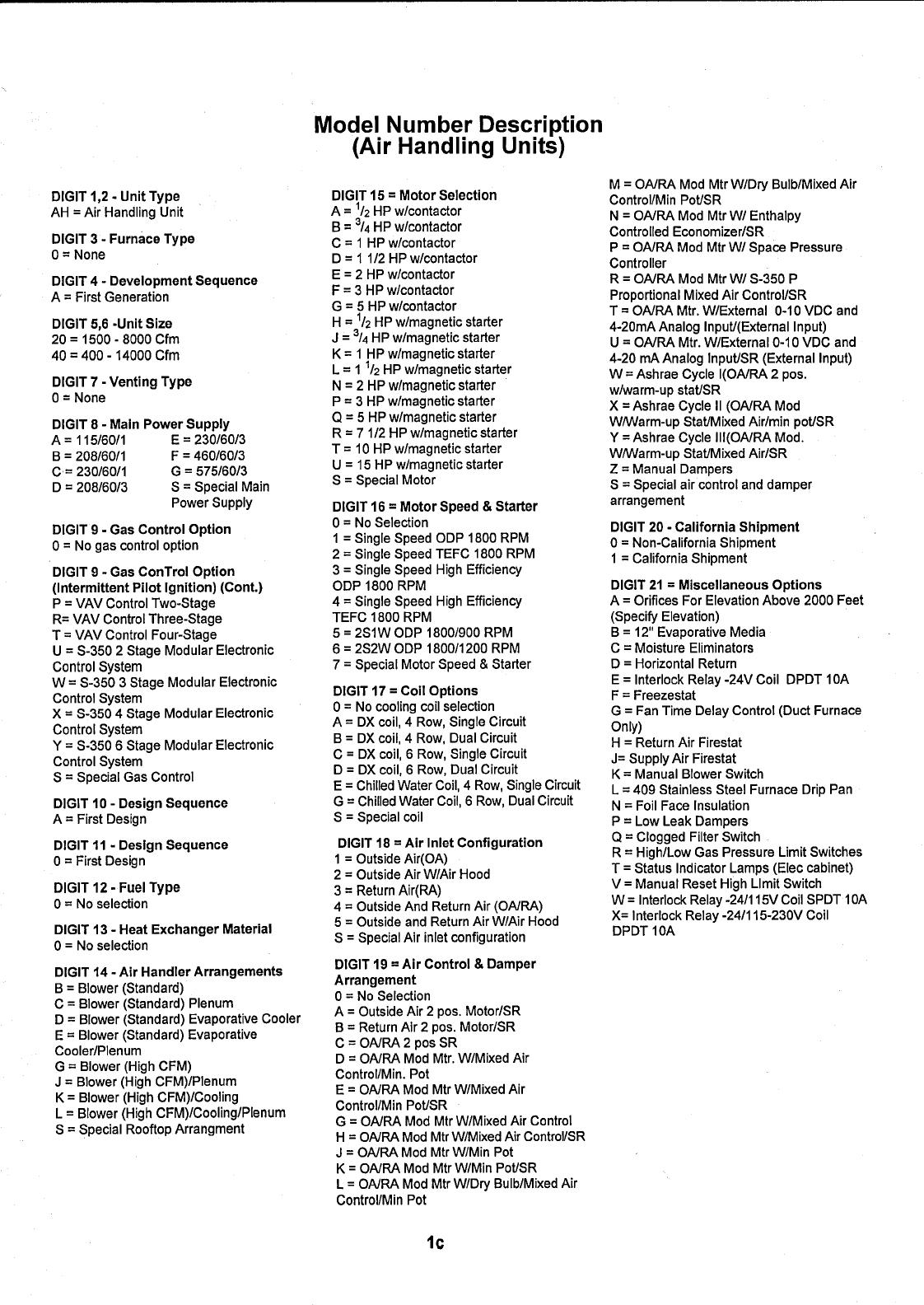
Model
Number
Description
(Air
Handling
Units)
D
I
GIT
1
,
2
-
U
nit
T
y
p
e
A
H
=
Air
Handling
U
nit
DIGIT
3
-
Furnace
Type
0
=
N
one
DIGIT
4
-
De
v
elopment
Sequence
A
=
F
irst
G
eneration
DIGIT
5
,
6
-
Unit
Size
20
=
1500
-
8000
C
fm
4
0
=
400
-
14000
Cf
m
DIGIT
7
-
Vent
i
ng
Type
0 =
N
one
DIGIT
8
-
Main
Power
Supply
A
=
115/60/1
E
=
230/60/3
B
=
208/60/1
F
=
460/60/3
C
=
230/60/1
G
=
575/60/3
D
= 208/60/3
S
=
Special
Main
Power
Supply
D
I
GIT
9
-
Gas
Control
Option
0 =
N
o
gas
con
t
rol
optio n
DIGIT
9
-
Gas
ConTrol
Option
(Intermittent
Pilot
Ign
i
tion)
(Cont
.
)
P
=
VAV
C
ontrol
Two-
St
age
R
=
VA
V
Con
t
rol
T
hree-Stage
T
=
VAV
Control
F
our-Stage
U
=
S
-350
2
S
t
age
Modular
E
lectronic
Control
System
W
=
S
-350
3
Stage
M
odular
E
lectronic
C
ontrol
System
X
=
S-350
4
Stage
M
o
d
ular
E
lectronic
Control
System
Y
=
S-350
6
Stage
M
odular
E
lectronic
Control
System
S
=
Special
Gas
C
ontrol
D
I
GIT
10
-
Design
Sequence
A
=
Firs
t
D
esign
DIGIT
11
-
Design
Sequence
0
=
First
Design
DIGIT
12
-
Fuel
Type
0
=
No
selection
DIGIT
13
-
Heat
Exchanger
M
aterial
0
=
No
selection
DIGIT
14
-
Air
Handler
Arrangements
B
=
Blower
(Standard)
C
=
Blower
(Standard)
Plenum
D
=
Blower
(Standard)
Evaporative
Cooler
E
=
Blower
(Standard)
Evaporative
Cooler/Plenum
G
=Blower
(High
CFM)
J
=Blower
(High
CFM)/Plenum
K
=Blower
(High
CFM)/Cooling
L
=Blower
(High
CFM)/Cooling/Plenum
S
=Special
Rooftop
Arrangment
DIGIT
15
=
Motor
Selection
A
=
1/2
HP
w/contactor
B
=
3/4
HP
w/contactor
C
=
1
HP
w/contactor
D
=
1
1/2
HP
w/contactor
E
=
2
HP
w/contactor
F
=
3
HP
w/contactor
G
=
5
HP
w/contactor
H
=
1/2
HP
w/magnetic
starter
J
=
3/4
HP
w/magnetic
starter
K
=
1
HP
w/magnetic
starter
L
=
1
1/2
HP
w/magnetic
starter
N
=
2
HP
w/magnetic
starter
P
=
3
HP
w/magnetic
starter
Q
=
5
HP
w/magnetic
starter
R
=
7
1/2
HP
w/magnetic
starter
T
=
10
HP
w/magnetic
starter
U
=
15
HP
w/magnetic
starter
S
=
Special
Motor
DIGIT
16
=
Motor
Speed
&
Starter
0
=
N
o
Selection
1
=
S
ingle
S
peed
O
D
P
1800
RP
M
2
=
Single
Speed
T
EF
C
1
800
RPM
3
=
Single
Speed
High
Efficiency
O
DP
1800
RP
M
4
=
S
ingle
S
peed
High
E
fficiency
TEF
C
1800
R
P
M
5
=
2
S1
W
O
D
P
1
800/900
R
P
M
6 =
2S2W
ODP
1800/1200
RP
M
7
=
Special
Motor
Speed
&
Starter
DIGIT
17
=
Co
l
l
Options
0
=
N
o
co
o
ling
coil
selection
A
=
DX
coil,
4
R
ow,
Single
C
ircuit
B
=
DX
coil,
4
R
ow,
D
ual
C
ircuit
C
=
DX
coil,
6
R
ow,
Single
C
ircuit
D
=
DX
coil,
6
R
ow,
D
ual
Circui
t
E
=
C
hilled
Water
Coil,
4
R
ow,
S
ingle
C
ircuit
G
=
C
hilled
Water
C
oil,
6
R
ow,
D
ual
C
ircuit
S
=
Special
coil
D
IGIT
18
=
Air
Inlet
Configuration
1
=
Outside
Air(OA)
2 =
Outside
Air
W/Air
Hood
3
=
Return
Air(RA)
4 =
Outside
And
Return
Air
(OA/RA)
5
=
Outside
and
Return
Air
W/Air
Hood
S
=
Special
Air
inlet
configuration
DIGIT
19
=
Air
Control
&
Damper
Arrangement
0
=
N
o
S
election
A
=
Outside
Air
2
pos.
Mo
t
or/S
R
B
=
R
eturn
Air
2
p
os.
M
otor/S
R
C
=
OA/
RA
2
pos
S
R
D
=
OA/
RA
M
o
d
Mtr.
W/
M
ixed
Air
C
ontrol/
M
in.
P
ot
E
=
OA/
RA
Mod
M
t
r
W/Mixed
A
ir
C
ontrol/Min
P
ot/
SR
G
=
O
A/
RA
M
od
M
ir
W/Mixed
Air
C
ontrol
H
=
OA/R
A
M
od
M
tr
W/Mixe
d
Air
C
ontroVS
R
J
=
O
A/
R
A
M
od
M
tr
W/
M
in
P
o
t
K
=
OA/
R
A
M
od
M
tr
W/
M
in
P
ot/
SR
L =
O
A/R
A
M
o d
Mtr
W/D
ry
B
ulb/
M
ixed
Air
Co
n
tr
ol/
M
in
P
ot
M
=
OA/
R
A
M
od
M
tr
W/
D
ry
B
ulb/
M
ixed
A
ir
C
ontrol/
M
in
P
ot/
SR
N
=
O
A/
R
A
M
od
Mtr
W/
E
nthalpy
C
ontrolled
E
conomi
z
er/
SR
P
=
O
A/
R
A
M
od
M
t
r
W
/
S
pace
P
ressure
Controller
R
=
OA/
R
A
M
od
M
tr
W/
S-350
P
P
roportional
M
ixed
A
ir
C
ontrol/
SR
T
=
OA/R
A
M
tr.
W/External
0
-10
VDC
and
4-20mAAnalog
I
n
p
ut/(External
Inpu
t
)
U
=
O
A/
RA
M
t r
.
W/
E
xternal
0-10
VDC
an
d
4
-
2 0
m
A
Analog
Inpu
t
/
SR
(
E
xternal
I
npu
t
)
W
=
Ashrae
C
ycle
I(
O
A/
RA
2
pos.
w/warm-up
stat/
SR
X
=
Ashrae
C
ycle
I
I
(OA/
RA
M
o d
W/Warm-u
p
Stat/
M
ixed
Air/min
p
ot/
SR
Y
=
Ashrae
Cycle
III(OA/
R
A
Mod.
W/Warm-up
Stat/
M
ixed
Air/S
R
Z
=
M
anual
D
ampers
S
=
Special
air
control
and
damper
arrangement
DIGIT
20
-
California
Sh
i
pment
0
=
N
on-
C
alifornia
Shipment
1
=
C
alifornia
Shipmen
t
DIGIT
21
=
Miscellaneous
Options
A
=
O
rifices
F
or
E
levation
A
bove
2000
(Specify
E
levation)
B
=
12"
Evaporative
M
edia
C
=
Mois
t
ure
E
liminators
D
=
Horizontal
R
eturn
E
=
Interlock
R
elay
-2
4
V
C
oil
DPDT
1
F
=
Freezestat
G
=
Fan
T
ime
D
elay
C
ontrol
(
D
uc
t
F
ur
Only)
H
= Return
Air
Firestat
J=
Supply
Air Firestat
K
=
Manual
Blower
Switch
Feet
OA
ace
L
=
409
Stainless
Steel
Furnace
Drip
Pan
N
=Foil
Face
Insulation
P
=Low
Leak
Dampers
Q
=Clogged
Filter
Switch
R
=High/Low
Gas
Pressure
Limit
Switches
T
=Status
Indicator
Lamps
(Elec
cabinet)
V
=
Manual
Reset
High
Limit
Switch
W
=Interlock
Relay
-24/115V
Coil
SPDT
10A
X=
Interlock
Relay
-24/115-230V
Coil
DPDT
10A
1c

TABLE
OF
CONTENTS
1 .
RECEIVING &
PRE
-
INSTALLATION
INSTRUCTIONS
Access
Panel
Removal
...:................
3
Rigging
........
....
................3
Combustion
Air
Considerations
..............
3
Location
.....................
.......3
Mounting
/
Locations
.....................
3
II
.
GENERAL
REQUIREMENTS
.............
3
III
.
INSTALLATION
Installation
Clearances
....................
5
Mounting
on
Field
Furnished
Supports
........
5
Mounting
on
Roof
Curb
...................
6
Venting
...............:................6
Duct
Connections.......
...........
...
6
Gas
Piping
...........................6
Modulating
Gas
Control
..
..............
.
8
'Electrical
Connections
...
...............
9
DX
Coil
Equipped
Units
..................
10
Chilled
Water
Coil
Equipped
Units
..........
11
Evaporative
Cooling
Equipped
Units
.........
11
IV
.
OPERATION
General
Information
.....................
11
Gas
Control
System
.....
........
.
.....
11
Optional
Gas
Controls
...
'
..............
12
Air
Handling
Requirements
and
A
djustments
.
.
12
Lighting
........... ...........
13
Gas
Input
Adjustment....
..............
14
Pilot
Adjustment
........................
14
Primary
Air
Shutter
Adjustment
.............
14
Controls
..............................14
V
.
START
UP
...........
...............
15
VI
.
MAINTENANCE
......!
...............
16
VII
.
TROUBLESHOOTING
................
19
VII
I.
REP
L
ACEMENT
PARTS
..............
24
IX
.
SERVICE
NOTE
.....
.............
24
X
.
START
UP
SHEET
....................
25
The
following
terms
are
used
throughout
this
manual
to
bring
attention
to
the
presence
of
potential
hazards
or
to
important
information
concerning
the
product:
CAUTION:
Indicates
an
imminently
hazardous
situa-
tion
which,
if
not
avoided,
may
result
in
minor
injury
or
property
damage.
NOTE:
Used
to
notify
of
special
instructions
on
instal-
lation,
operation
or
maintenance
which
are
important
to
equipment
but
not
related
to
personal
injury
haz-
ards.
1 .
RECEIVING
INSTRUCTIONS
Inspect
shipment
immediately
when
received
to deter-
mine
if
any
damage
has
occurred
to
the
crate
during
ship-
ment.
After
the
unit
has
been
uncrated,
check
for
any
visible
damage
to
the
unit.
Check
motor
position
and
turn
blower
wheel
to
determine
if
damage
has
occurred
to
these
criti-
cal parts.
If
any
damage
is
found,
the
cosignee
should
sign
the
bill
of
lading
indicating
such
damage
and
immediately
file
claim
for
damage
with
transportation
company.
PRE
-
INSTALLATION
INSTRUCTIONS
W
he
n
the
u
nit
i
s
received
and
uncrated,
check
the
exter-
nal
data
plate
and
all
labels
on
the
unit
for
type
of gas,
electrica
l ,
and
operational
specifications
to confir
m
tha
t
t
hese
agree
with
those
at
point
o
f
installation.
If
the
unit
is
equipped
with
an
Outdoor
Duct
Furnace,
also
check
the
d
ata
plate
and
all
labels
located
inside
each
furnace.
Every
rooftop
unit
will
include
an
informational
packet
which
will
include
the
following:
The
blower
manual,
out-
door
duct
furnace
and
evaporative
cooler/cooling
coil
manuals
(if
applicable
to
the
unit
order),
wiring
diagram(s),
and
special
controls/data
sheets.
ACCESS
PANEL
REMOVAL
Each
access
panel
is
held
in
place
with
two
"grip"
latches.
To
remove
an
access
panel:
use
a
slotted
head
screw
dri-
ver
to turn
the
latch
screwhead
counter
clockwise.
Using
the
handle
provided,
push
the
panel
upwards.
Pull
the
bot-
tom
of
the
panel
out
and
lower
the
panel
to
disengage
it
from
the
top
lip.
To
replace
an
access
door
panel,
guide
-2-

the
panel
door
upwards
on
the
tracks,
and
push
up
into
the
top
lip,
swing
and
lower
the
panel
in
place
until
it
engages
with
the
bottom
panel.
Turn
the
screwhead
on
each
latch
clockwise.
The
screw
must
turn
freely
one
quarter
turn
before
resistance
is
felt
in
order
for
the
lock
to
engage.
If
latch
does
not
hold,
turn
screw
counter-clock-
wise
several
turns
and
repeat
the
above
procedure.
RIGGING
Rig
unit
using
either
belt
or
cable
slings.
Use
spreader
bars
to
protect
the
top
of
the
unit
when
it
is
lifted.
See
fig-
ure
1.
On
units
with
a
total
length of
less
than
104"
(2642
mm),
excluding
evaporative
cooler,
two
holes are
provided
in
the
base
rail
on
each
side
of
the
unit.
Slide
pipes
beneath
the
unit
through
these
holes
and
attach
rigging
to
pipes
for
lifting
the
unit.
On
units
with
a
total
length
of
a
104"
(2642
mm)
or
greater,
excluding
evaporative
cooler,
lifting
lugs
attached
to
the
base
rail
are
provided.
Attach
rigging to
lugs
for
lifting
the
unit.
For
distance
between
lifting
lugs
and
total
unit
lengths,
refer
to
original
Submittal
Sheets
supplied
specified
for
the
unit.
Also
see
Center
of
Gravity
and
Weights
Sections
in
this
manual.
COMBUSTION
AIR
CONSIDERATIONS
The
presence
of
chlorine
vapors
or
other
corrosive
vapors
in
the
combustion
air
supply
for
gas-fired
heating
equip-
ment
presents
a
potential
corrosive
hazard.
Chlorine
will,
when
exposed
to
flame,
precipitate
from
the
compound
(usually
freon
or
degreaser
vapors)
and
go
into
solution
with
any
condensation
that
is
present
in
the
heat
exchang-
er or
associated
parts.
The
result
is
hydrochloric
acid
which
will
readily
attack
all
metals,
including
300
grade
stainless
steel.
Care
should
be
taken
to
separate
these
vapors
from
the
combustion
process.
This
may
be
done
by
wise
location
of
the
unit
with
regard
to
exhausters
or
prevailing
wind
direction.
LOCATION
Before
placing
roofto
p
unit
in
its
permanent
location,
make
certain
that
the
roof
is
capable
of
carrying
the
additional
load
of
this
equipment.
Check
the
unit
weight
given
at
the
end
of
this
manual.
Refer
to
Figure
2
for
required
clearances
to
combustible
material.
Figure
1
USE
SPRE
A
D
T
O
PREVE
N
TI
T
O
U
N
I
USE SPRE
A
DE R
BAR
T
O
PRE V
E
N
T
DAMAGE
T
O
UN
IT
MOUNTING/
LOCATIONS
These
units
are
suitable
for
installation
on
combustible
flooring.
Single,
double
and
triple
duct
furnace
only
models
have
base
rails
which
can
be
mounted
either
on
solid
planking
or
steel
channels.
All
other
units
installed
on
field
furnished
supports
must
use
the
recommended
method
shown
in
Mounting
on
Field
Furnished
Supports
or
equivalent.
Roof
curb
kits
for
rooftop
units
are
shipped
unassembled.
Included
with
the
roof
curb
kit
are
insulated
or
uninsulated
curb
rails,
bolts
and
screws
needed
for
assembly,
sealant,
a
roll
of
self-adhering
rubber
gasketing,
and
installation
instructions.
Roof
insulation,
cant
stripping,
flashing,
roof
felts,
caulking,
and
nails
must
be
furnished
by
the
installer.
See
separate
roof
curb
specifications.
II
.
GENERAL
REQUIREMENTS
-3-

The
venting
is
an
integral
part
of
the
unit
and
must
not
be
altered
in
the
field.
The
Natural
Vented
units
are
equipped
with
a
ventcap
which
is
designed
for
natural
draft
venting.
Air
for
combustion
enters
the
base
of
the
vent
cap
through
a
protective
grill
and
products
of
com-
bustion
are
discharged
at
the
upper
section
of
the vent
cap.
CAUTION
:
Insure
that
all
power
sources
conform
to
th
e
un
i
t
requirements
or
damage
to
the
unit
may
result
Installation
must
be
made
in
accordance
with
local
codes,
or
in
the
absence
of
local
codes,
with
the
latest
edition
of
ANSI
Standard
Z223.1
(N.F.P.A.
No.
54)
National
Fuel
Gas
Code.
All
of
the
AN
SI
and
N
FPA
Standards
referred
to
in
these
installation
instructions
are
those
that
were
applicable
at
the time
the
design
was
certified.
The
ANSI
Standards
are
available
from
the
American
Gas
Association,
1515
Wilson
Blvd.,
Arlington,
Virginia
22209.
The
NFPA
Standards
are
available
from
the
N
ational
Fire
Protection
Association,
Batterymarch
Park,
Quincy,
MA
02269.
If
installed
in
Canada,
the
installation
must
conform
with
local
building
codes,
or
in
the
absence
of
local
building
codes,
with
the
current
CAN/CGA-B149.1
or
B149.2
"Installation
Codes
for
Gas
Burning
Appliances
and
Equipment'.
T
hese
outdoor
duct
furnaces
have
been
designed
for
and
certified
to
comply
with
CAN/CGA
2.8.
These
units
have
been
designed
cert
i
f
i
ed
for
outdoor
u
se
only
,
and
may
be
located
on
the
roof of
the
building
or
at
any
convenient
location
external
to
the
building
to
be
heated.
This
vent
cap
is
shipped
in
a
separate
carton
and
should
be
installed
per
the
Venting
section
of
the
Outdoor
Rooftop
Gas-Fired Duct
Furnace
Installation
and
Service
Manual.
The
Power
Vented
unit
has
a
induced
draft
venting
system.
The
combustion
air
inlet
and
prod-
ucts
of
combustion
discharge
grills
are
located
in
the
upper
section
of
the
Duct
Furnace
side
access
panel.
A
pilot
burner
plate
is
provided
in
the
Duct
Furnace
for
access
to
the
pilot
burner
and
ignition
system
without
removing
the
burner
drawer.
Clearance
between
the
external
unit
and
any
obstruction
must be
sufficient
for
proper
servicing
of
pull
out
burner
drawer.
See
Figure
2
for
this
clearance.
These
units
are
certified
for
operation
on
either
natural
or
propane
gases.
If
a
unit
is
to
be
installed
at
an
altitude
exceeding
2000
feet
(610
m)
above
sea
level,
Berate
the
unit
input
of
each
duct
furnace
by
4%
for
each
1000
feet
(305
m)
above
sea
level.
Special
main
burner
gas
orifices
are
required
for
installations
above
2000
feet
(610
m).
In
Canada,
if
unit
is
to
be
installed
at altitudes
of
2000
feet
(610
m)
to
4500
feet
(1372
m),
each
duct
furnace
must
have
the
main
burners
re-orificed to
give
90%
of
the
normal
altitude
input
rating.
If
the
unit
was
ordered
from
the
factory
for
high
altitude
operation
,
confirm
input
rating
.
See
Gas
Input
Adjustment
.
re
2A
,a
.
ow•
.
3
125
(
8
)
3
g
<.x)
-4-

Figure
2B
18"
(457
mm)
A
I
R
FLOW
(45
7
mm)
Blower
c
0
U
0
U
U
W
Duct
Furnace
I
Duct
F
urnace
D3
8
6 5
F*
"`
Refer
to
Outdoor
Duct
Furnace
Manual
for
spec
i
fic
clearances
.
Supply
Plenum
16"--
.
(457
mm)
If
a
single,
double
or
triple
duct
furnace
only
unit
is
III
.
INSTALLATION
connected
to
a
return
air
duct
or
any
other
inlet air
restriction,
the
appliance
shall
be
installed
on
the
positive
pressure
side
of
the
air
circulating
blower.
Installation
must
conform
with
local
building
codes
or
in
the
absence
of
local
codes
with
the
National
Fuel
Gas
Code
ANSI
Z223
.
1
latest
edi
-
t
i
on
.
A
heat
loss
study
and
a
complete
layout
of
the
sys-
tem
should
be
made
first.
When
locating
the
unit
in
its
permanent
location,
make
certain
that
the
roof
is
capable
of
carrying
the
additional
load
of
the
equipment.
Check
the
unit
net
weights
section
of
this
manual
.
Make
certain
that
clearances
are
provided
for
ser-
vice,
minimum
clearance
to
combustible
material
and
to
venting
cap.
See
figure
2
for
this
information.
Ducts
connected
to
units
which
do
not
have
either
a
blower
section
or
a supply
plenum
must
have
a
removable
access
panel
in
the
duct,
which
is
con-
nected
to
a
duct
furnace.
The
duct
openings
shall
be
accessible
when
the
unit
is
installed
in
service
and
shall
be
of
such
size that
smoke
or
reflected
light
may
be
observed
inside
the
casing
to
indicate
the
presence
of
leaks
in
the
heating
element.
The
covers
for
the
panels
shall
be
attached
in
such
manner
as
to
prevent
leaks.
Ducts
exposed
to
the
outdoors
must
be
insulated
and
sealed
to
prevent
water
from
enter-
ing
either
the
unit
or
building
through
the
duct.
CAUTION:
Remove
wooden
shipping
support
from
beneath
blower
housing
of
Blower
Section
to
prevent
possible
unit
damage
or
improper
unit
operation
(if
applicable).
INSTALLATION
CLEARANCES
Minimum
clearances
to
combustible
material
are
shown
on
the
unit
data
plate.
It
is
important
that
clearances
be
maintained
for
servicing
the
unit
(refer
to
Submittal
Insert
for
service clearances),
and
that
minimum
clearances
are
provided
from
the
unit
(including
vent
cap,
if
Natural
Vent
model)
to
com-
bustible
material.
Clearances
around
the
outside
air
hood
(if
unit
is
so
equipped)
must
be
unobstructed.
See
Figure
2.
MOUNTING
ON
FIELD
FURNISHED
SUPPORTS
Single,
double,
triple
duct
furnace
only
models
have
base
rails
which
are
suitable
for
mounting
either
directly
on
solid
planking
or
steel
channels.
N
ever
install
the
unit
on
a
soft
roof
where
the
rails
could
sink,
reducing
clearance
between
the
bottom
panel
and
the
roof,
or
cause
damage
to
the
roofing surface.
All
other
models
must
use
the
following
method
or
an
equivalent
when
unit
supports
are
field
furnished:
Each
section
of
the
Rooftop
unit
must
be
supported,
which
includes
supports
located
at
both ends.
If
the
unit
consists
of
a
High
CFM
Blower
section,
a
DX
Coil,
a
Duct
Furnace
and
a
Supply Plenum,
five
sup-
ports
are
required.
See
Figure
3.
-5-

3
Suppo
rt
m
us
t
clear
return
a
i
r
o
penin
g
a
n
d
f
i
t
Ins
i
de
b
ase
rai
l
f
la
n
g e
.
See
Figures
4
&
13
for
this
dimension.
Support
must
fit
inside
base
rail
f
lang
e
s.
MOUNTING
ON
ROOF
CURB
Assemble
and
install
roof
curb
per
Roof
Curb
Installation
Instructions.
See
Figures
4
&
13
for
roof
opening
sizes,
distance
between
openings
and
unit
relationship
to
roof
curb.
VENTINGt
All
venting
installations
shall
be
in
accordance
with
the
latest
edition
of
Part
7
,
"Venting
of
Equipment",
of
the
National
Fuel
Gas
Code,
ANSI
Z223.1-1992
(or
the
latest
edition),
or
applicable
provisions
of
local
building
codes.
The
Natural
Vente
d
u
nits'...
are
equipped
with
a
vent
cap
which
is
designed
for
n
atural
draft
venting.
Air
for
combustion
enters the
base
of
the
vent
cap
through
a
protective
grill
and
produc
t
s
of
combustion
are
dis-
charged
at
the
upper
section
of
the
vent
cap.
t
Th
i
s
ve
nt
c
a
p
i
s
sh
i
pped
in
a
separate
carton
and
s
hould
be
installed
per
the
Venting
section
of
the
Outdo
or
Rooftop
Gas
-
F
i
red
Duct
Fu
r
na
c
e
In
s
t
a
lla
ti
on and
Service
Manual
.
The
Power
Vented
unit
has
a
induced
draft
venting
system.
The
combustion
air
inlet
and
products
of
combustion
discharge
louvers
are
located
in
the
upper
section
of
the
Duct
Furnace
side
access
panel.
Never
locate
these
units
in
an
area
where
the
flue
products
discharge
outlet
may
be
directed
at
any
fresh
air
vents.
See
the
Outdoor
Rooftop
Gas-Fired
Duct
Furnace
Installation
and
Service
M
anual
for
installation
and
servicing
requirements.
DUCT
CONNECTIONS
All
ductwork
must
be
properly
supported
so
that
no
strain
is
put
on
the
unit.
Do
not
alter
or
bend
the
dis-
charge
duct
flanges
supplied
on
your
furnace/air
handler.
Ducts
connected
to
units
which
do
not
have
either
a
blower
section
or
a
supply
plenum
must
have
a
removable
access
panel
in
the
duct
which
is
con-
nected
to
a
duct
furnace.
The
duct
openings
shall
be
accessible
when
the
unit
is
installed
in
service,
and
shall
be
of
such
size
that
smoke
or
reflected
light
may
be
observed
inside
the
casing
to
indicate
the
presence
of
leaks
in
the
heating
element.
The
covers
for
the
panels
shall
be
attached
in
such
a
manner
as
to
prevent
leaks.
Ducts
exposed
to
the
outdoors
must
be
insulated
and
sealed
to
prevent
water
from
either
the
unit
or
building
through
the
duct.
If
a
single,
double
or
triple
duct
furnace
only
unit
is
connected
to
a
return
air
duct,
or
any
other
inlet
air
restriction,
the
appliance
shall
be
installed
on
the
positive
pressure
side
of
the
air
circulating
blower.
When
connecting
return
air
duct
to
Standard
or
High
CFM
cabinets,
attach
duct
to
return
air
opening
flange
when
no
dampers
are
used.
Otherwise,
if
dampers
are
used,
attach
return
air
duct
around
col-
lar
at
bottom
of
damper
assembly. Also
refer
to
the
Submittal
Data
Sheets
specified
for
your
unit.
When
connecting
supply
air
duct
to
Supply
Plenum,
attach
duct
to
supply
air
opening
flange
when
no
dampers
are used.
Otherwise,
if
dampers
are used,
attach
supply
air
duct
around
collar
at
bottom
of
damper
assembly.
Refer
to
the
Figure
13.
GAS
PIPING
tt
All
gas
piping
must
be
installed
in
accordance
with
local
codes.
It
is
required
that
a
ground
union
be
installed
adjacent
to
the
gas
valve
of
each
duct
fur-
nace,
and
a
ground
union
be
installed
just
external
of
each
duct
furnace
for
unit
servicing.
On
vertical
runs,
a
drip
leg
should
be
provided
upstream
of
any
con-
trol
manifold.
A
gas
shutoff
valve
should
be,
or
may
be
required
by
local
codes,
installed
upstream
of
the
external
ground
union
for
each
duct
furnace.
A
1/8
inch
N.P.T.
plugged
tapping,
accessible
for
test
gauge
connection,
must
be
installed
immediately
upstream
of
the
unit
gas
supply
connection.
tt
For
complete
Gas
Piping
installation,
see
Outdoor
Rooftop
Gas-Fired
Duct
Furnace
Installation
and
Service
Manual.
It
is
recommended
that
the
gas
piping
not
be
installed
through
the
bottom
of
the
duct
furnace
bot-
tom
panel.
If
piping
must
penetrate
the
duct
furnace
bottom
panel,
it
must
be
sealed
to
prevent
water
leakage.
Gas
piping
must
be
installed
to
allow
for
removal
of
burner
drawer
for
unit
maintenance.
Refer
to
Figure
2.
-6-

Figure
4
CURB
SPECIFICATIONS
*
ROOF
OPENINGS
UNIT
TYPE
UTJ
"RT,
PVOrAH
"
CAPAC
I
TY
DIMENSION
[
CA]
'
R
E
TURN
SUPPLY
26
00
AIR
B*
AIR
10/
1
5
(660)
OP
E
NING
OPENING
37
.
00
20/25/50
(940)
30
/
35
/
60170
48
.
^
(1219)
40
/
80/12
53
.
50
(1359)
20
.
875
A*
20
.
875
ALL
DIMENSIONS
SHOWN
HAVE
BEEN
(530) (530)
CALCULATED
TO
INCLUDE
A
ONE
(1)
INCH
CLEARANCE
AROUND
RETURN
AND
SUPPLY
DUCTS
.
**
U
ROOFTOP
z
ARRANGEMENT
1
[RA]
LL
C,
E
J
J
^
z
L
UNIT
TYPE[
UTJ
"AT
orPV"
UNIT
SPECIFICATIONS
(REFERENCES)
CAPACITY
BLOWER
COIL
SUPPLY
DIMENSION
[CA]
STD.
HIGH
CFM
PLENUM
A"
10
-
40
^
.
J
50.85
(1292)
20
-
40
87.04
(2211)
10
-
40
113.
0
2
(2871)
UMT
TYPE!
LIT)
AH
"
BLOWER
[
R
A
I
[CA]
ST
'
D
.
HI
COI
L
SUPPLY
A
20 24
.
859
N,R
or
40
(631)
20
^
.
J
61
.
047
T
or
40
(1551)
W
20
.
J
^
.
J
87
.
035
or
40
(2211)
C
,
E
50
-80
76.
84
(
1
952)
113.02
J
M
5
0
-
80
(
2
871
)
139.01
L
50
-
80
(353
1
)
J
^
12
^
.^
1
39.01
(35
31
)
• '
ROO
FT
OP
ARR
A
NG
E
ME
NTS
[
RA
]
B,
D
,
G,
K,
M
,
P
,
S
& U
ARE
WITHOUT
A
S
UPP
L
Y
P
L
EN
U
M
;
U
SE
THE
SA
M
E
RE
TUR
N
A
IR
D
IME
N
SIO
N
S
F
O
R
THES
E
UNITS
R
OOFTO
P
O
PE N
I
N
GS.
REFE
R
TO
U
N
I
T
SUB
M
I
TTA
LS
FO
R
M
OR
E
D
E
TA
IL.
UNIT
4
.
00
(102)
RUBBER
GASK
ET
1
2
.
00
(3
0
5)
ROOF
U
NI
T
BASE
R
A
IL
F
L
AN
GE
WI
T
H
C
URB
CAP
1
.
00
NAI
L
NAILER
(WOOD
STRIP)
CANT
FELT
DIMENSIONS
ARE
IN
INCHES
D
I
MENSIONS
IN
()
ARE
IN
MM
.
.
375
(10)
CLEARANCE
SHOULD
BE
MAINTAINED
ON
EACH
SIDE
TO
INSURE
PROPER
INSTALLATION
.
-7-

CAUTION
:
Do
not
over
-
tighten
the
inlet
gas
pip-
ing
at
unit
gas
valve
or
stresses
that
could
crack
the
valve
may
result
.
The
gas
line
should
be
supported
so
that
no
strain
is
placed
on
the
unit.
Pipe
compounds
which
are
not
soluble
to
liquid
petroleum
gases
must
be used
on
threaded
joints.
The
appliance
and
its
individual
shutoff
valve
must
be
disconnected from
the
gas
supply
piping
system
during
any
pressure
testing
of that
system
at
test
pressures
in
excess
of
1/2
psig
(3.5
kPa).
The
appliance
must
be
isolated
from
the
gas
supply
piping
system
by
closing
the
individual
manual
shut-
off
valve
during
any
pressure
testing
of
the
gas
sup-
ply
piping
system
at
test
pressures
equal
to
or
less
than
1/2
psig
(3.5
kPa).
;
For
additional
gas
piping information,
including
pipe
sizing
and
drip
leg
installation,
refer
to
Outdoor
Rooftop
Gas-Fired
Duct
Furnace
Installation
and
Service
Manual.
For
additional
piping
information,
refer
to
the
National
Fuel
Gas
Code
Z233.1
(latest edition).
NOTE
:
If
the
gas
duct
furnace
is
to
be
fired
with
LP
gas
,
consult
local
LP
gas
dealer
for
pip
i
ng
size
information
.
NOTE
:
UNIT
INSTALLATION
FOR
USE
WITH
PROPANE
(BOTTLED)
GAS
MUST
BE
MADE
BY
A
QUALIFIED
LP
GAS
DEALER
OR
INSTALLER
.
HE
WILL
INSURE
PROPER
JOINT
COMPOUNDS
ARE USED FOR
MAKING
PIPE
CONNECTIONS
;
THAT
AIR
IS
PURGED
FROM
LINES
;
THAT
A
THOROUGH
TEST
IS
MADE
FOR
LEAKS
BEFORE
OPERATING
THE
UNIT
;
AND
THAT
IT
IS
PROPERLY
CONNECTED
TO
PROPANE
GAS
SUPPLY
SYSTEM
.
Before
any
connection
is
made
to
an
existing
line
supplying
other
gas
appliances,
contact
the
local
gas
company
to
make
certain
that
the
existing
line
is
of
adequate
size
to
handle
the
combined
load.
Check
all
connections
for
leaks
with
soap
solution.
MODULATING
GAS
CONTROL
(OPT
I
ONAL)
*
Mechanic
a
l :
On
units
equipped
with
mechanical
modulating
gas
control,
the
temperature
sensing
bulb
for
the
gas
valve
must
be
field
installed
in
the
supply
plenum.
Carefully
uncoil
the
capillary
tubing
to
prevent
kinking
or
sharp
bends.
CAUTION:
Do
not
bend
the
capillary
tubing
with-
in
1/2"
(12.7
mm)
of
the
connection
to
the
bulb
or
the
valve.
Repeated
bending
may
cause
the
tub-
ing
to
leak
or
break.
Center
and
fasten
the
temperature sensing
bulb
in
the
supply
duct
at
least
2
inches
below
the
last
duct
furnace
section.
See
Figure
5.
Figure
5
Electronic
:
On
units
(natural
gas
only)
equipped
with electronic
modulating
control,
follow control
manufacturer's
installation
instructions
for
sensing
of
outlet
air
temperature.
*
Also
refer
to
the
Outdoor
Duct
Furnace
Installation
Manual
supplied
with
your
unit.
-8-
Caution:
Do
not
rely
on
a
gas
shutoff
valve
to
iso-
late
the
unit
while
conducting
gas
pressure/leak
tests.
These
valves
may
not
be
completely
shut-
off,
exposing
the
unit
gas
valve
to
excessive
pressure,
resulting
in
damage.

ELECTRICAL
CONNECTIONS
All
electrical
connections
must
conform
to:
ANSI/NFPA
No.
70-1993
(or
latest
edition)
National
Electrical
Code
and
applicable
local
codes.
In
Canada,
to
the
Canadian
Electrical
Code,
Part
I
CSA
Standard
C22.1.
The
rooftop
packaged
unit
is
wired
at
the
factory
and
ready
to
be
connected.
Actual
unit
wiring
will
differ
according
to
the
options
chosen.
Each
furnace
is
shipped
with
its
own
wiring
diagram;
refer
to
this
wiring
diagram
for
all
electrical
connections
to
the
unit.
All
electrical
connections,
line
voltage
and
thermo-
stat,
are
made
in
the
Electrical
Cabinet
(See
Figure
6).
Line
voltage
connections
are
made
at
the
High
Voltage
Terminal
Block.
Thermostat
connections
are
made
at
the
Main
Connection
Board
(See
figure
7).
CAUTION
:
Do
not
use
any
tools
(i
.
e
.
screwdriver
,
pliers
,
etc
.
)
across
terminals
to
check
for
power
.
Use
of
a
voltmeter
is
recommended
.
Outdoor
line
voltage
conduits
leading
into
the
unit
should
be
installed
to
prevent
rain
from
wetting
any
high
voltage
wire.
Locate
the
thermostat
in
accor-
dance
the
instructions
supplied
with
the
thermostat.
All
field
wiring
must
have
a
minimum
temperature
rating of
85°
C
(185°
F).
Thermostat
wiring
shall
be
a
minimum
of
18
gauge
wire
size.
See
the
following
charts
for
line
voltage
wire
sizes.
Figure
6
.
-
Standard
Blower
Cabinet
,
Single
Duct
Furnace
with
Supply
Plenum
&
Various
Options
Shown
1
.
Mixed
Air
Controll
e
r
2
.
Return
Firestat
3
.
Econom
i
zer
4
.
Filters
5.
Bl
o
w
er
M
otor
6
.
R
e
verse
Air
Flow
Sw
i
tch
7
.
Clog
g
ed
F
ilter
S
w
itch
8
.
Hi
gh
V
oltag
e
B
arrier
and
L
am
p
and
C
i
rcuit
Breaker
Mount
9
.
Main
Connect
i
on
Board
with
Fan
Time
Delay
and
Function
Relays
10
.
Powe
r
V
e
nt
o
r
R
ela
y
11
.
Freezestat
12
.
Supply
Fir
es
t
a
t
13
.
Duct
T
h
e
r
m
o
s
t
a
t
14.
Primary
Safety
Limit
15.
Power
Ventor
Motor
16.
Gas
Piping
Limit
17.
Gas
Valve
18.
High
Limit
Safety
Switch
19.
Transformer
20.
Electrical
Wiring
Inlet
21.
High
Voltage
Terminal
Block
22.
Door
Safety
Switch
23.
Contactor
24.
Centrifugal
Blower
25.
Damper
Motor
26.
Outside
and
Return
Dampers
27.
Enthalpy
Controlled
Economizer
-9-
Intake
Hood
Dampers/Filters
Electrical
Duc
t
Supp
l
y
Blower
Cabinet
Cabinet
F
urnace
Plenum

7
-
Electrical
Cabinet
Low
Voltage
Sect
High
Voltag
e
Sec
I
L
Locate
line
voltage
disconnect
box
per
local
codes.
If
mounting
the
disconnect
box
to
the
unit,
never
mount
it
to
an
unit
access
panel.
Possible
locations
include
the
front
of
the
blower
or
filter
section,
the
outdoor
air
hood
or
the
rear
of
the
supply
plenum
(See
Figure
8).
Electrical
conduit
must
be
routed
so
as
not
to
inter-
fere
with
removal
of
any
access
panel.
NOTE
:
Should
any
or
i
g
i
nal
wire
suppl
i
ed
with
the
unit
hav
e
to
be
replaced
,
it
must
b
e
replaced
w
i
th
w
iri
ng
h
a
v
i
ng
a
temp
e
rature
r
a
t
i
ng
of
at
least
105
°
C
(221
°
F)
.
DX
COIL
EQU
I
PPED
UNITS (OPTIONAL)
See
Coil
Installation/Maintenance
Manual
for
Refrigerant
Piping,
Liquid
and
Suction
Line
Components,
Refrigerant
Charging
and
Thermal
Expansion
Valve
Adjustment.
Remove
piping
plate
located
in
lower
corner
next
to
filter
section
and
cut
holes
in
plate
to
allow
suction
and
liquid line
pas-
sage.
Provide
weatherproof
seal
around'suction
and
liquid
lines
at
piping
plate
when
installed.
The
DX
Coil
has
a
300
ft/min.
(1.524
m/s)
minimum
and
a
600
ft/min.
(3.048'
m/s)
maximum
velocity
through
the
coil
requirement.
This
is
due
to
preven-
tion
of
coil
icing
or
condensate
blow-off.
To
calculate
the
velocity
through
the
coil,
apply
the
following
for-
mula:
Velocity
Cooling
Air
Flow
in
CFM
(m3/s)
through
the
coil
^
Coil
Surface
Area
in
ft2
(m2)
opt
i
o
n
al
C
o
nt
rol
s
Jo
u
n
ci
ng
Locat
io
n
1Q
Back
Panel
OZ
main
connection
Board
Q
High
Voltage
Barrier
Assy
O4
24V
Transformer
Q5
High
Voltage
Terminal
Block
O8
Ground
Lug
O7
Din
Mounting
Rail
Contactor
or
Starter
1
D3
88
3
S
-
uisconnect
tJox
vocations
Di
s
conn
e
ct
9
D
i
scon
n
e
c
t
B
o
x
Located
On
Int
ake
E
n d
Pane
l
(Ret
ur
n
A
i
r
O
nl
y)
D
(acann
e
et
B
ox
Locat
ed
On
Out
s id
e
A
ir
Hood
iii
S
U
PP
L
Y
AIR
Disconnect
Bo
x
Locat
e
d
On
Supply
Pl
e
num
End
Pan
e
l
D3-9-6-6
Condensate
Drain
piping
must
have
a
P-trap
in
line
immediately
downstream
of
drain
pan
connection,
external
to
the
unit,
to
prevent
possible
outside
air
-10-

6
8
44
-101H
-/
leakage
into
unit.
The
P-trap
shall
be
of
sufficient
dif-
ferential
to
overcome
negative
pressure
of
the
indoor
air
blower.
A
minimum
height
difference
of
2"
is
required
(See
Figure
9).
Before
unit
operation
begins,
the
P-trap
must
be
primed
with
either
water
(summer)
or
glycol
(winter).
CHILLED
WATER
CO
I
L
EQU
I
PP
E
D
UN
I
TS
(
OP
TI
ONAL
)
See
Coil
Installation/Maintenance
Manual
for
General
Coil
Piping
Recommendations.
Remove
pip-
ing
plate
located
in
the
near
center
of
the
coil
cabinet
and
cut
holes
in
plate
to
allow
chilled
water
piping
passage.
Provide
weatherproof
seal
around
chilled
water
pipes
at
piping
plate
when
installed.
Figure
9
-
Drain
Pan
Connection
DRAIN
PAN
CONNECTION
UNIT
2
"
MIN
.
D3Bb7
The
Chilled
Water
Coil
has
a
600
ft/min
(3.048 m/s)
maximum
velocity
through
the
coil
requirement.
This
is
due
to
prevention
of
condensate
blow-off.
To
cal-
culate
the
velocity
through
the
coil
apply
the
follow-
ing
formula:
Velocity
Cooling
Air
Flow
in
CFM
(m3/s)
through
the
coil
Coil
Surface
Area
in
ft2
(m2)
Condensate
Drain
piping
must
have
a
P-trap
in
line
immediately
downstream
of
drain
pan
connection,
external
to
the
unit,
to
prevent
possible
outside
air
leakage
into
unit.
The
P-trap
shall
be
of
sufficient
dif-
ferential
to
overcome
negative
pressure
of
the
indoor
air
blower.
A
minimum
height
difference
of
2"
is
required
(See
Figure
9).
Before
unit
operation
begins,
prime
P-trap
with
either
water
(summer)
or
glycol
(winter).
EVAPORATIVE
COOLER
EQUIPPED
UNITS
(OPTIONAL)
Refer
to
Evaporative
Cooler
Installation
and
Service
Manual
for
water
and
electrical
connections.
IV
.
OPERATION
GENERAL
INFORMATION
Refer
to
Outdoor
Rooftop
Gas-Fired
Duct
Furnace
Installation
and
Service
Manual
for
specific
informa-
tion
regarding
the
heating
operation
of
this
unit.
All
units
are
equipped
with
a
intermittent
ignition
pilot
system.
The
pilot
is
lit
and
extinguished
each
cycle
of
unit
heating
operation.
Outlet
mu
s
t
be
b
e
low
u
ni
t
co
nne
c
t
ion
The
lockout
function
shuts
off
the
main
and
pilot
gas
valves
if
the
pilot
gas
fails
to
ignite
within
90
seconds
of
the
onset
of
trial
for ignition.
In
order
to
initiate
a
re-
ignition
trial,
the
power
supply
must
be
interrupted
for
30
seconds.
The
gas
control
system
operates
at
24
VAC
and
is
supplied
by
a
stepdown
transformer
found
in
the
electrical
cabinet
that
will
match
the
unit
line
voltage
specified.
See
Figure
6
for
unit
controls
location.
Do
not
use
a
thermostatic
fan
control
switch
when
either
two-stage
firing
or
modulated
gas
controls
are
used.
NOTE
:
Electronic
modulating
gas
controls
are
available
on
natural
gas
units
only
.
These
con-
trols
are
not
ava
i
lable
with
propane
units
.
GAS
CONTROL
SYST
E
M
The
standard
unit
comes
equipped
for
single
stage
operation.
Unit
heating
operation
is
accomplished
at
full
input.
Each
duct
furnace
is
equipped
with
an
individual
igni-
tion
control
system
which
consists
of
the
following
components:
ignition
control
module,
gas
valve
and
pilot
burner.
The
ignition
control
module
is
the
heart
of
the
igni-
tion
control
system.
This
control
initiates
all
gas
flow,
provides
means
to
light
the
pilot
burner,
proves
and
monitors
the
pilot
burner
operation.
The
gas
valve
consists
of
two
operators
which
pro-
vide
gas
to
the
pilot
and
main
burners.
Both
opera-
tors
are
energized
and
de-energized
by
the
ignition
control
module
each
heating
cycle.
On
natural
gas
units,
the
ignitor
will
continue
to
spark
and
pilot
gas
will
continue
to
flow
until
the
pilot
flame
The
pilot
burner
includes
an
ignitor
and
flame
sense
is
proven.
probe.
The
ignitor
provides
the
spark,
originating
at
the
ignition
control
module,
to
light
the
pilot.
The
igni-
LP
(propane)
units
are
equipped
with
100%
lockout.
tion
control
module
proves
and
monitors
the
pilot
flame
through
the
flame
sensing
probe.
-
11
-

All
units
follow
the
same
basic
sequence
of
operation
and
is
as
follows:
1.
Thermostat
calls
for
heat.
Power
vented
units
only
:
D
raftor
relay
ener-
gizes
draftor
with
call
for
heat.
2.
Ignition
control
module
energizes
pilot
operator
of
gas
valve
and
initiates
spark
at
ignitor
of
the
pilot
burner.
3.
Pilot
burner
ignition
is
proven
to
the
ignition
con-
trol
by
the
flame
sense
probe
and
sparking
of
the
ignitor
is
discontinued.
4.
Once
pilot
burner
operation
is
proven,
the
ignition
control
module
energizes
the
main
burner
opera-
tor
of
the
gas
valve,
allowing
gas
flow
to
the
main
burners.
Po
we
r
v
e
nt
e
d
un
i
ts
only
:
In
addition,
draftor
operation
must
be
proven
by
draftor
end
switch
before
ignition
control
module
energizes
main
burner
operator
of
gas
valve.
5.
Approximately
60
seconds
after
the
main
burners
light
the
fan
time
delay
initiates
fan
operation.
6.
Thermostat
is
satisfied
and
call
for
heat
is
removed.
Pow
er
v
e
nted
units
only
:
Draftor
relay
de-ener-
gizes
draftor
with
removal
of
call
for
heat.
7.
Ignition
control
module
de-energizes
pilot
and
main
burner
operators
of
the
gas
valve,
ceasing
all
gas
flow.
8.
Approximately
two
minutes
after
satisfying
the
thermostat,
fan
operation
ceases.
OPTIONAL
GAS
CONTROLS
These
units
are
available
with
optional
gas
controls
which
will
give
either
multi-stage
or
modulating
oper-
ation.
The
sequence
of
operation
of
those
units
equipped
with
these
optional
gas
controls
differs
only
at
what
rate
each
duct
furnace's
main
burners
ignite
and
operate
at
or
the
order
of
duct
furnace
firing
for
those
units
equipped
with
two
or
three
duct
furnaces.
Two
Stage
Units
:
Two
stages
of
heating;
first
stage
is
40%
of
full
rate,
second
stage
is
100%
of
full
rate.
Main
burner
ignition
is
at
first
stage
only.
Th
ree
St
a
g
e
Units
:
Triple
duct
furnace
models
only.
Each
duct
furnace
is
equipped
with
single
stage
heating
but
fired
independently,
giving
three
stages.
Each
stage
is
33%
of
the
unit's
full
input
rate.
Duct
furnace
one
will
always
light
first
and
disengage
last.
Four
St
a
ge
Un
i
ts
:
Dual
duct
furnace
models
only.
Each
duct
furnace
is
equipped
with
two
stage
heat-
ing
but
fired
independently,
giving
four
stages.
Each
stage
is
25%
of
the
units
full
input
rate.
Duct
furnace
one
will
always
light
first
and
disengage
last.
Six
Stage
Un
i
ts
:
Triple
duct
furnace
models
only.
Each
duct
furnace
is
equipped
with
two
stage
heat-
ing
but
fired
independently
giving
six
stages.
E
ach
stage
is
16.5%
of
the
units
full
input
rate.
Duct
fur-
nace
one
will
always
light
first
and
disengage
last.
Mechanical
Modulation
Units
:
These
units
are
equipped
with
a
hydraulic
modulating
control
which
provides
unit
firing
capabilities
of
40
to
100%
of
the
units
full
input
rate.
This
control
is
found
in
the
gas
train
downstream
of
the
gas
valve
and
allows
main
burner
ignition
only
at
the
minimum
rate.
A
tempera-
ture
sensing
bulb,
located
in
the
discharge
airstream,
controls
the
level
of
modulation.
These
units
are
available
with
a
modulation
bypass
which
will
give
single
stage
or
full
input
operation.
Electronic
Modulation
Units
:
(Not
available
with
propane
units)
These
units
are
equipped
with
a
elec-
tronic
modulating
control
which
provides
unit
firing
capabilities
of
40
to
100%
of
the
units
full
input
rate.
This
control
is
found
in
the
gas
train
downstream
of
the
gas
valve
and
allows
main
burner
ignition
only
at
the
maximum
rate.
A
thermostat
with
remote
setpoint
adjustment
modulates
the
gas
input.
Multi
-
Stage
w
/
Electronic
Modulation
Units
:(
N
ot
available with
propane
units)
T
hese
dual
and
triple
duct
furnace
models
are
equipped
with
an
electronic
modulating
control
on
duct
f
urnace
one and
single
or
two
stage
heating
on
each
successive
duct
furnace.
Furnace
one
(modulated)
will
fire
first
and
disengage
last.
Additional
stages
of
heat
will
engage
after
fur-
nace
one
has
fired
at
maximum
modulation
capabili-
ty
for
the
duration
of
the
delay
setting.
The
amount
of
modulation
and
each
stage
size
depends
upon
unit
size
and
the
number
of
stages.
See
following
chart.
Modulation
Stage
Number
Capabilities
Size
of
Stages
(%
of
full
Input)
(%
of
full
Input)
2
25
-
50
50
3
16.5
-
33
33
4
25
-50
25
6
16
.
5
-
33
16.5
AIR
HANDLING
REQUIREMENTS
AND
ADJUSTMENTS
CAUTION
:
Remove
wooden
shipping
support
from
beneath
blower
housing
of
Blower
Section
to
prevent
possible
unit
damage
or
improper
unit
operation
(if
applicable)
.
-12-

Static
Pressure
through
the
unit
should
never
exceed
2.0"
W.C.
(0.50
kPa).
The
standard
unit
is
operated
at
a
temperature
rise
range
of
20
to
60
F°
(11
to
33
CO).
The
high
temperature
rise
model
is
operated
at
a
temperature
rise
range
of
60
to
90
F°
(33
to
50
CO).
NOTE
:
It
is
important
that
the
final
temperature
leaving
the
unit
does
not
exceed
160
0
F
(71
°
C)
.
When
final
air
throughput adjustments
are
being
made
,
a
check
of
the
discharge
air
temperature
should
be
made
after
unit
has
operated
for
15
to
20
minutes
.
CAUTION
:
A
unit
should
never
be
allowed
to
cycle
on
the
primary
limit
for
a
prolonged
period
of
time
.
It
is
a
safety
control
to
prevent
a
fire
.
If
cycling
on
the
primary
limit
is
noted
,
corrective
measures
should
be
taken
immediately
.
Failure
to
do
so
could
result
in
unit
damage
or
a
fire
.
NOTE
:
At
initial
unit
installation
,
unit
should
be
started
momentarily
to
confirm
proper
blower
wheel
rotation
as
the
unit
will
deliver
some
air
with
the
blower
wheel
running
backwards
.
Two
basic
air
control
systems
can
be
used
to
deliver
conditioned
air
to
the
occupied
space:
intermittent
or
constant
fan
operation.
Intermittent
Fan
Operation
:
The
unit
employs
an
air
control
system
which
utilizes
a
fan
time
delay
relay
to
operate
the
fan
while heating
and
the
thermostat
while
cooling.
Refer
to
unit
wiring
diagram.
Constant Fan
Operation:
The
unit
can
be
wired
to
give
an
air
control
system
which
constantly
circulates
air
through
the
unit
and
occupied
space
with
con-
stant
fan
operation.
Refer
to
unit
wiring
diagram.
NOTE:
Check
blower
belt
tension.
Proper
belt
tension
is
important
to
the
long
life
of
the
belt
and
motor.
Proper
belt
tension
will
allow the
belt
to
be
depressed
1/2"
to
3/4".
It
is
important
that
the
blower
motor
and
the
blower
wheel
pulleys
be
in
good
alignment,
with
the
motor
and
blower
shafts
parallel.
Belt
tension
must
be
adjusted
to
give
approximately
3/4"
deflection
of
the
belt
when
finger
pressure
is
applied
to
the
middle
of
the
belt
(See
Figure
10).
Small
changes
in
this
tension
may
be
necessary
for
optimum
operation.
Belts
will
stretch
over
a
period
of
time,
requiring
an
adjustment
to
this
tension.
See
MAINTENANCE
section
for
belt
and
pulley adjust=
ments.
These
units
are
set
at
the
factory
for
the
RPM
required
to
meet
the
air
volume
(CFM)
and
external
static
pressure
ordered.
If
the
estimated
external
sta-
tic
is
incorrect,
or
changes were
made
to
the
duct
system,
the
blower
RPM
may
need
to
be
changed.
Both
the
Standard
and
High
CFM
Blowers
use
motors
which
are
equipped
with
adjustable
pitch
pul-
leys.
After
removing
belt(s),
loosen
the
pulley
set
screw
and
remove
the
key,
turn
adjustable
half
of
a
pulley
clockwise
to
increase
RPM,
or
counter-clock-
wise
to
decrease
RPM.
Insert
key,
tighten
set
screw
and
replace
belt(s).
Adjust
belt
tension
to
give
1/2"
to
3/4"
belt
play
when
depressed.
CAUTION
:
Blower
motor
fu
l l
load
amps
should
never
b
e
exc
ee
d
e
d
.
Improper
un
i
t
op
e
r
a
t
i
on
or
motor
failure
could
result
.
After
changing
blower
RPM,
confirm
blower
motor
full
load
amps
have
not
been
exceeded
.
See
motor
data
plate
for
max
i
mum
full
load
amps
.
L
I
GHT
I
NG
(Refer
to
Outdoor
Duct
Furnace
Manual
for
all
heat-
ing
functions
-
general
comments
are
as
follows.)
Purge
the
gas
line to
the
unit of
air
before
attempting
to
light
the
pilot.
Check
for
gas
leaks.
This
unit
is
equipped
with
an
intermittent
ignition
sys-
tem.
A
lighting
instruction
is
attached
to
the
unit.
To
set
the
intermittent
ignition
system
into
operation
proceed
as
follows:
1.
Turn
on
the
gas
valve(s)
main
manual
valve.
2.
Turn
on
electrical
power.
The
unit
is
now
under
thermostat
control.
-13-

3.
Set
thermostat
to
highest
level.
This
will
initiate
the
sequence
of
operation
detailed
in
the
Gas
Control
System
section.
Check
main
burners
for
operation.
4.
Set
thermostat
to
lowest
level.
This
will
Interrupt
power
to
the
ignition
control
and
shut
off
gas.
Confirm
pilot
and
main
burners
have
been
extin-
guished.
5.
Set
the
thermostat
to
the
desired
setting.
For
complete
unit
shutdown,
proceed
as
follows:
1.
Turn
off
the
gas
valve(s)
main
manual
valve.
2.
Set
thermostat
to
lowest
setting.
3
.
Shut
off
all
electr
i
c
power
.
GAS
INPUT
ADJUSTMENT
When
shipped from
the
factory,
all
equipped
for
the
average
heat
content
which
is
stamped
on
the
unit
rating
plate.
units
are
of
the
,
gas
CAUTION
:
Since
the
heat
'
cont
e
nt
of
gas
varies
by
locality
,
the
input
must
be checked
after
instal
-
l
ati
on
of
t
he
un
i
t
.
If
th
e
un
i
t
i
s
ov
e
rfired
i
t
wi
l
l
shorten
the
life
of
the
heat
exchanger
.
Never
exceed
the
input
on
the
rating
plat
e.
For.
an
accurate
input
rate
measurement
the
follow-
ing
meter
method
should
be
used
to
determine
unit
input
rate.
If
the
meter
method
is
not
possible,
a
manifold
pressure
check
should
be
made.
Meter
Method
of
Checking
Input
Rate
1.
Obtain
the
heating
value
of
the
gas
from
the
local
utility
or
gas
dealer.
This
should
be
in
units
of
Btu/ft3
(MJ/m3).
2.
Determine
the
gas
flow
rate
as
shown
in
the
fol-
lowing
example.
EXAM
PL
E
:
Assume
this unit
has
a
input
rate of
250,000
B
tu/hr
(73.2
kW)
and
the
heating
value
of
the
gas
is
1
000
Btu/ft3
(37.3
MJ/m3).
Gas
250,000
Btu/hr
(73.2
kW)
Flow
=
1000
Rate
Btu/ft3
(37.3
MJ/m3)
x
60
min/hr
=
4.17
ft3/min
(1.974
Us)
Before determining
the
gas
flow
rate
to
the
unit,
all
other
gas
appliances
connected
to
the
same
meter
must
be
turned
off.
Fire
unit
according
to
instructions.
After
approximately
15
minutes
of
unit
operation,
determine
volume
of
gas
used
in
five
minutes
of
3
.
4
.
5
.
unit
operation.
For
the
Example
above
the
unit
should
use
4.17
ft3/min
x
5
minor
20.8
ft3
(1.97
Us
x
5
min
x
60
s/min
=
591
L)
of
gas.
Minor
input
adjustments
can be
made
by
removing
pressure
regulator
cap
and
turning
regulator
clockwise
to
increase
input
or
counter
clockwise
to
decrease
input.
Any
appreciable
adjustment
in
input
rate
should
be
made
by
reorificing.
Method
to
Check
Manifold
Pressure
1.
Close
the
manual
valve
of
unit
gas
valve.
2.
Install
a'1/8"
pipe
connection
in
the
tapped
hole
provided
in
the
gas
valve
body
near
outlet of
the
valve.
3.
Attach
manometer
to'1/8"
pipe
connection
by
means
of
a
rubber
hose.
4.
Fire
unit
according
to
instructions
and
observe
the
pressure
and
confirm
it
matches
the
unit
manifold
pressure
from
the
unit
rating
plate.
5.
Small
variations
in
the
manifold
pressure
can
be
made
by
means
of
the
gas
valve
pressure
regu-
lator.
Remove
pressure
regulator
cap
and
turn
regulator
clockwise
to
increase
pressure
or
counter-clockwise
to
decrease
pressure.
P
I
LOT
ADJUSTMENT
1.
Disconnect
wire
from
terminal
marked
MV
at
gas
valve.
2.
Provide
call
for
heat.
3.
Pilot
adjustment
is
found
on
the
gas
valve.
Remove
pilot
adjustment
cap.
4.
Adjust
the
pilot
screw
to
provide
properly
sized
flame.
5.
A
proper
pilot
burner
flame
is
a
soft
steady
flame
that
envelopes
3/8
to
1/2
inch
(9.5
to
12.7
mm)
of
the
flame
sense
probe
tip.
6.
Replace
the
pilot
adjustment
cap.
PR
I
MARY
AIR
SHUTTER
ADJUSTMENT
After
the
unit
has
been
in
operation
for
at
least
15
minutes,
adjust
the
primary
air
flow
to
the
burners.
Turn
the
friction-locked
manually
rotated
air
shutters
clockwise
to
close,
counter
clockwise
to
open.
For
correct
air
adjustment,
close
the
air
shutter
until
yel-
low
tips
in
the
flame
appear.
Then
open
the
air
shut-
ter
to
the
point
just
beyond
the
position
where
yellow
tipping
disappears.
CONTROLS
Primary
L
i
mit
Control
:
The
primary
limit
control
is
a
factory
installed
component
surface
mounted
in
the
14-

inlet
airstream
at
the
end
of
the
heat
exchanger.
When
the
temperature
reaches
the
limit
setpoint,
normally
caused
by
insufficient
air
throughput,
all
gas
is
shutoff
.
The
limit
control
has an
automatic
reset
and
once
the
unit
has
cooled,
it
will
reset
itself
.
This
is
a
safety
control
and
if
cycling
on
the
primary
limit
is
noted,
corrective action
must
be
taken.
See
unit
wiring
diagram
for
electrical
location.
This
control
must
never
be
bypassed.
Upon
completion
of
unit
installation,
the
primary
limit
must be
checked
for
proper
operation.
This
can be
accomplished
by
\
removing
power
to
the
indoor
air
blower
and
a
call
for
heat.
Draftor
End
Switch
:
This
switch
is
located
at
the
end
of
the
draftor
motor
and
is
integral
to
the motor.
The
switch,
whic
h
is
normally
open,
will
close
when
draftor
motor
attains
the
minimum
speed
for
proper
combustion
allowing
main
burner
operation.
The
pilot
burner
will
light
without
a
proven
draftor
end
switch.
See
unit
wiring
diagram
for
electrical
location.
Clogged
Filter
Switch:
(Optional)
The
clogged
filter
switch
monitors
the
pressure
differential
across
the
air
filters.
If
this
pressure
differential
becomes
too
great,
the
switch
will
alert
of
this
condition.
At
this
point
the
air
filters
must
either
be
cleaned
or
replaced.
The
switch
will
reset
itself.
Firestat:
(Optional)
Located
in
either
the
return
airstream,
the
supply
airstream,
or
both,
this
control
monitors
temperatures
with
setpoints
which
are
field
adjustable.
If
the
temperature
exceeds
the
setpoint,
the
control
will
cease
unit
operation.
To
resume
unit
operation,
a
manual
reset
of
this
control
is
required.
Freezestat:
(Optional)
Located
in
either
the
return
airstream,
the
supply
airstream,
or
both,
this
control
monitors
temperatures
with
setpoints
which
are
field
adjustable.
If
the
temperature
does
not
exceed
the
setpoint,
the
control
will
cease
unit
operation.
V.
START
UP
Before
starting
the
unit,
use
the
"Installation
Check
Sheet"
(located
at
the
end
of
this
manual)
and
read
the
Outdoor
Duct
Furnace
Manual
entirely
in
con-
junction
with
the
procedures
outlined
below
to
ensure
that
the
unit
is
completely
and
properly
installed
and
ready
for
start
up.
1.
Inspect
all
wiring
connections;
connections
should
be
clean
and
tight.
Trace
circuits
to
insure
that
actual
wiring
agrees
with
the
"as
wired"
diagrams
provided
with
the
unit.
Information
in
the
wiring
diagram
title
block
should
match
the
data
appearing
on
the
unit
nameplate.
2.
Lubricate
all
electrical
motors
according
to
the
manufacturer
'
s
recommendations
.
3.
Verify that
the
system
switch
is
in
the
OFF
position.
4.
Check
unit
supply
voltage
to
ensure
that
it
is
within
the
utilization
range.
5.
Inspect
the
interior
of
the
unit;
remove
any
debris
or tools
which
may
be
present.
Starting
Unit
in
Heating
Mode
1
.
Close
the
un
i
t
disconnect
switch
which
provides
p
owe
r t
o
th
e
u
nit
.
3.
Place
the
system
switch
in
the
ON
position.
With
the
thermostat
calling
for
heat,
unit
operation
is
automatic.
Starting
Unit
in
Cooling
Mode
1.
Close
the
unit
disconnect
switch
which
provides
power
to
the
unit.
3.
Place
the
system
switch
in
the
ON
position.
With
the
thermostat
calling
for
cooling,
unit
operation
is
automatic.
-15-
2.
Set
the
thermostat/switching
subbase
as
indicat-
ed
below:
a.
position
the
heating
system
switch
at
either
HEAT
'
or
AUTO;
b
:
set the fan
switch
to
AUTO.
2.
Set
the
thermostat/switching
subbase
as
indicat-
ed
below:
a.
position
the cooling
system
switch
at
either
COOL
or
AUTO;
b.
set
the
fan
switch
to
AUTO.

Final
Checkout
Run
the
unit
sequentially
through
its
stages
of
heat-
ing
and
cooling.
Once
proper
unit
operation
is
veri-
fied,
perform
these
final
steps:
1.
Inspect
unit
for
debris
and/or
misplaced
t
ools
and
hardware.
2.
Be
sure
all
gas
valves
and
controls
are
in
the
operating
position
if
the
unit
will
be
operating
immediately.
3.
Cycle
unit
on
all
safety
controls
to
verify
proper
unit
operation.
4.
Confirm
proper
operating
control
(thermostat
or
ductstat)
operation
by
cycling
unit.
5.
Secure
all
exterior
panels
in
place.
VI
.
MAINTENANCE
nace;
swing
downward
the
piping
to
clear
drawer.
3.
Disconnect
duct furnace
gas
valve
wiring
taking
note
of
all
wire
locations.
Disconnect
ignitor
and
flame
sensing
probe
wires
at
ignition
control
module
and
any
other
wires.
4.
Remove
the
locking
screws
holding
the
burner-
drawer
assembly
in
position.
5.
Slide
the
burner
drawer
out
of
the
duct
furnace.
6.
Removal
of
burners
is
accomplished
by
sliding
burner
towards
manifold,
compressing
locating
spring,
until
the
rear
of
the
burner
clears
slot
in
back
of
burner
drawer.
7.
With
burner
drawer
removed
from
duct
furnace,
inspect
the
inside
surfaces
of
the
heat
exchang-
er.
Wire
brush
if
necessary.
8.
Remove
any
dirt,
dust
or
other
foreign
matter
from
the
burners
using
a
wire
brush
and/or
com-
pressed
air.
Insure
all
parts
of
the
burner
are
unobstructed.
Inspect
and
clean
pilot
burner
if
necessary.
9.
Reassemble
the
duct
furnace
by
replacing
all
parts
in
order.
10.
Light
unit
per
the
unit
lighting
instructions.
These
units
have
been
developed
for
outdoor
instal-
lation.
Maintenance
is
required
and
it
is
suggested
that
the
following
unit
servicing
and
inspections
be
performed
routinely.
Also read
in
entirety
and
refer
to
the
Outdoor
Duct
Furnace
Manual
for
maintenance
requirements.
Inspect
area
near
unit
to
be
sure
that
there
is
no
combustible
material
located
within
the
minimum
clearance
requirements
(See
Figure
2).
Service
pan-
els
provide
easy
access
to
the
gas
controls
(located
in
duct
furnace
section),
the
blower
compartment,
the
electrical
cabinet
and
the
supply
plenum.
To
remove
the
service
door
from
any
of
these
compart-
ments,
refer
to
access
panel
removal
section
in
beginning
of this
manual.
The
pilot
burner
can
be
serviced
by
removing
the
pilot
plate
from
the
main
burner
drawer
assembly.
To
remove
the
main
burner
drawer
assembly
(also
refer
to
Outdoor
Rooftop
Duct
Furnace
Installation
and
Service
Manual)
for
servicing
the
burners,
pro-
ceed
as
follows:
1.
Shut
off
the
gas
supply
at
the
gas
shutoff
valve
and
electrical
power
to
the
unit.
2.
Break
the
union
upstream
of
duct
furnace
gas
valve
and
loosen
the
union
external
to
the
fur-
11.
Check
the
burner
adjustment.
See
the
"Primary
Air
Adjustment'
section
of
this
manual.
12.
Check
all
gas
control
valves
and
pipe
connec-
tions
for
leaks.
13.Check
the
operation
of
the
duct
furnace
gas
valve
by
lowering
the
setting
of
the
thermostat,
stopping
the
operation
of
the
duct
furnace.
The
duct
furnace
gas
valve
should
close,
extinguish-
ing
the
pilot
and
main
burner
flames.
14.
Inspect
and
service
the
blower
section
of
the
system.
The
unit
should
be
thoroughly
checked
before
the
start
and
at
the
end
of
each
heating
and
cooling
season.
1.
Motors
and
belts
should
be
inspected.
2.
Tighten
belts
if
loose.
-16-
/