Page is loading ...

CCBR3-G176-803
CCBR3
CCBR3
CHAR
BROILER
(RADIANT HEATING)
Texas Restaurant Equipment
12922 Hempstead Hwy
Houston, TX 77040
P: (713) 690-1231

notes

General Installation
FOR YOUR SAFETY
DO NOT STORE OR USE GASOLINE OR OTHER FLAMMABLE VAPOURS OR
LIQUIDS IN THE VICINITY OF THIS OR OTHER APPLIANCE. KEEP THE
APPLIANCE AREA CLEAR AND FREE FROM COMBUSTIBLES
IT IS VITAL THAT INSTRUCTION BE POSTED IN
A PROMINENT LOCATION TO BE FOLLOWED IN
THE EVENT OF THE USER SMELLING GAS!
CAUTION
This equipment is designed and sold for commercial use only by personel trained
and experienced in this operation and is not sold for consumer use in and around
the home nor for use directly by the general public in food service locations.
This equipment is adjusted to be used with the type of gas indicated on the
nameplate on the rear of the unit.
WARNING: Improper installation, adjustment,
alteration, service or maintenance can cause
property damage, injury or death. Read the
installation, operating and maintenance
instructions thoroughly before installing or
servicing the equipment.
1
!
!
Item Code Description
CHAR BROILER
(CCBR3)
Obs.: To use the cast iron flat plate remove grates and the radiant.
The flat plate works directly over the burner and horizontally.
1
2
3
4
5
6
7
8
9
10
11
12
13
14
15
16
17
18
19
20
21
22
23
24
25
26
27
28
29
30
31
32
33
Grates
Radiant Element
Burner
Inlet Pipe
Shut Off Valve
Pilot Pipe
Gas Colector Pipe
Pilot Valve
Heat Chamber
Grease Pan
Body
Tray
Foot
Front Panel
Air Regulator
Gas Tap
Gas Injection Device
Flame Control Indication
Knob
Grates’ Holder
Pressure Regulator
Screw
Screw (3/16”)
Screw (3/16”)
Flat Plate
Screw
Nut
Washer (3/16”)
O Ring
Pilot Burner
Tap Plug
Nut
Screw (3,5)
42.510-3
2.509-3
16.025-3
2.633-3
2.585-3
18.743-3
16.013-3
2.598-3
18.732-3
2.669-3
18.750-3
18.754-3
1.918-3
2.674-3
16.076-3
2.584-3
18.761-3
1.342-3
1.965-3
18.751-3
2.679-3
563
328
384
46.017-3
556
604
643
510
16.002-3
16.195-3
16.015-3
552
Power (BTU/h)
Consumption (g/h)
Weigth (kg/lbs)
Dimensions WxHxD (cm/in)
3 x 11.000
3 x 275 (LPG)
45.0/99.0
75/29.5 x 41/16.2 x 74/29.1
CCBR3-G176-803
Technical Data

Safety Precautions
For your safety, the following safety precautions should be followed and enforced:
1) Instructions must be posted in a prominent location and all safety precautions
takes in the event the user smells gas. Obtain this information from your local gas
supplier.
IF YOU SMELL GAS !!!
A) OPEN WINDOWS
B) DO NOT TOUCH ELECTRICAL SWITCHES OR PLUGS
C) EXTINGUISH ANY OPEN FLAMES
D) IMMEDIATELY CALL YOUR GAS SUPPLIER
2) Install this appliance in non-combustible locations only.
3) Do not place combustible or non-combustible material in the vicinity of the
equipment as this cloud cause fires or obstruct airflow to the burners.
4) The installation must conform with local codes; or in the absence of local
codes, with the National Fuel Gas Code ANSI Z223.1 (latest edition) or the
Natural Gas Installation Code CAN/CGA - B149.1 or the propane Installation
Code CAN/CGA - B149.2 as applicable.
5) The appliances must be isolated from the gas supply piping systen by closing
its individual manual shut off valve during any pressure testing of the gas
supply piping system at test pressures equal to or less than ½” PSI.
6) For the protection, we recommend a competent installation agency install this
appliance.
7) Retain this manual for future reference
2
CHAR BROILER
(CCBR3)
16
17
18
19
1
20
9
26
14
13
10
3
11
25
12
23
26
7
28
27
24
5
4
8
32
6
30
29
2
33
15
31
21
22

Installation Instructions
1) Unpacking and checking
Unpack the product and check for any damage occurred during transit.
This should be reported to the responsible carrier, railway or postal authority and a
request for damage report must be made.
2) Rating Plate
It is essential that when communicating with the factory, the model and serial
numbers be quoted. Other information on this plate is the operating gas pressure
in inches WC, BTU/h input of the burners, and whether the unit is orificed for
natural or propane gas.
PLEASE NOTE THAT THE APPLIANCE MUST ONLY BE CONNECTED TO THE
TYPE OF GAS IDENTIFIED ON THE RATING PLATE.
3) Leveling Unit
The Griddle is provided with feet that can be adjustable to level the unit.
4)Clearances and positioning
Check clearances in the rating plate. Keep the original feet in place to allow air to
enter the combustion chambers and do not obstruct the front of the equipment.
5) Air Supply and Ventilation
The area in front of the equipment and must be kept clear to avoid any obstruction
of the flow of combustion and ventilation air.
DO NOT REMOVE THE LEGS FROM UNDER THE UNIT!!
6) Pressure Regulator
All commercial cooking equipment must have a pressure regulator on the incoming
service line for safe efficient operation, since service pressure may fluctuate with
local demand.
a) Depending on whether natural gas or propane is required, a pressure regulator
must be installed with the unit.
b) Failure to install a pressure regulator will void the equipment warranty!
c) Care must be taken to ensure that the regulator is not installed in a high heat
area.
d) Prior to connect the regulator, check the incoming line pressure, as these
regulators can only with stand a maximum pressure of ½”PSI (14”WC). If the
line pressure is beyond this limit, a step down regulator will be required.
3
Cleaning
1) This appliance should NOT be cleaned with a water jet or immersed in water. Use only
a damp cloth or sponge dipped in soapy water.
2) Wipe off appliance with a dry cloth.
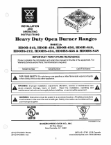
Outline sketch of CGR3G/CCBR3/CCBP3
(All dimension in mm)
6
680
3040
580
½”BSP MALE
715
750
100
205
105

Operating Instructions
1) Ensure that the gas supply is connected and the manual shut off valve is open.
2) Fire a flame in a long stick, depress the knob of the burner control and turn to “HI”
position.
3) Approximate the flame to the burner through the guide tube and the burner will start. At
this time the respective pilot burner will fire too.
4) Do item 2~3 for all burners to have pilot burners lighted.
5) When burners are lighted, adjust the knob to until the desired flame setting is achieved.
6) Before cooking on the appliance for the first time, clean the surface and turn the control
to maximum heat and allow it to BURN IN for approximately 20 minutes. You will notice
smoke appearing due to the protective coating residues burning off. THIS IS NORMAL.
7) After burn-in time has elapsed, turn the control knob down to the required operating
temperature and grease plate/grate generously with butter or oil. Never allow excess
fat or oil to build up as this will result in excess deposits of carbon on the plate.
8) It may be necessary to adjust the burner air shutter and the Low flame setting. This
needs to be undertaken only after initial installation and should only be required once.
To adjust the above, the following procedure needs to be followed:
a) Remove cooking top (grates or plate).
b) Remove radiant element and its grates (for Charbroiler version only).
c) Ignite all burners
d) Set each burner to “Low” position.
If the flame is too small or inconsistent an adjustment can be done by removing the
control knob and setting the gas flow using the screw in the center of the axle of the
gas valve.
e) Burner adjustment (must be done without the front panel - #14):
1) Turn burner knob to “HI” position.
2) Slowly turn the air regulator (drawing num.15) towards the burner tube to give a
soft blue flame having luminous tips, then slowly turn the air regulator back to a point
where the yellow tips disappear and a hard blue flame is obtained.
f) Shut down instructions
1) Any of the burners can be shutdown individually by turning the relevant knobs to
the “OFF” position.
2) Should a complete shutdown be required, turn the manual shut off valve in the
appliance and in the gas line.
3) Allow a 5 minute complete shut off period before re-lighting the appliance.
5
e) Any adjustment to the regulator may only be made by qualified service
personnel.
7) Gas Conversion
Conversion from Propane to Natural Gas or vice versa may only be performed by
the factory or its authorized service agent.
In case of troubleshooting, ensure that the correct orifice sizes of the spuds have
been provided.
PLEASE NOTE!
ORIFICE FOR NATURAL GAS IS: 1.6mm DIAMETER
ORIFICE FOR L.P. GAS IS: 0.9mm DIAMETER
8) Gas Connection
(For the installation code, see note 4 in the Safety Precaution)
9) Gas Piping
Gas piping shall be of such size and so installed as to provide a supply of gas sufficient
to meet the full gas input of the appliance. If the appliance is to be connected to
existing piping, it shall be checked to determine if it has adequate capacity. Joint
compound (pipe dope) shall be used sparingly and only on the male threads of the
pipe joints. Such compounds shall be resistant to the action of L.P. gases.
WARNING: Any loose dirt or metal particles, which are allowed to enter the gas lines
on this appliance, will damage the valve and affect its operation. When installing this
appliance, all pipe and fittings must be free from all internal loose dirt.
10) Manual Shut Off Valve
A manual shut off valve should be installed upstream from the manifold and within six
feet of the appliance and in a position where it can be reached in event of an
emergency, however the appliance is equipped with a manual shut off valve located
under the body in the right side that can be actuated in case of necessity.
!
4
/