Page is loading ...

OPERATOR’S MANUAL 612041-X
2” AIR MOTOR
1:1 RATIO
0 - 150 P.S.I. RANGE
INCLUDE MANUAL: S-632 GENERAL INFORMATION (PN 97999-624)
INCLUDING: SPECIFICATIONS, SERVICE KITS, GENERAL INFORMATION, PARTS, TROUBLESHOOTING
2” DIFFERENTIAL
TRANSFER PUMP
READ THIS MANUAL CAREFULLY BEFORE INSTALLING,
OPERATING OR SERVICING THIS EQUIPMENT.
It is the responsibility of the employer to place this information in the hands of the operator. Keep for future reference.
612042-X
SERVICE KITS
SPECIFICATIONS
Model Series 61204X-X. . . . . . . . . . . . . . . . .
Type Air Operated, transfer pump. . . . . . . . . . . . . . . . . . . . . . .
Ratio 1:1. . . . . . . . . . . . . . . . . . . . . . .
Air Motor Diameter 2’’ (5.08 cm). . . . . . . . . . . .
Stroke 6’’ (15.24 cm). . . . . . . . . . . . . . . . . . . .
Air Inlet (female) 1/4 - 18 N.P.T.F. - 1. . . . . . . . . . . . .
Material Inlet immersed. . . . . . . . . . . . . . .
Material Outlet (female) 3/4 - 14 N.P.T.F. - 1. . . . . . .
Pump Construction Carbon Steel. . . . . . . . . .
Dimensional Data See Chart. . . . . . . . . . . . .
Weight See Chart. . . . . . . . . . . . . . . . . . . . . .
PERFORMANCE
Air Inlet Pressure Range 0 - 150 p.s.i. (0 - 10.3 bar). . . . . . . .
Fluid Pressure Range 0 - 150 p.s.i. (0 - 10.3 bar). . . . . . . . . .
Maximum Rec’d Cycles / Minute 75. .
Displacement In
3
Per Cycle 18.8. . . . . .
Volume / Cycle 10.4 oz. (307.7 ml). . . . . . . . . . . . . . . .
Cycles Per Gallon 12.3. . . . . . . . . . . . .
Maximum Working Flow Rate 6 g.p.m. (22.7 l.p.m.). . . .
Maximum Flow Rate 18 g.p.m. (68.1 l.p.m.). . . . . . . . . . .
Noise Level @ 60 p.s.i., 40 c.p.m. 77.8 db(A)*. .
* Thepumpsoundpressure levelhasbeenupdatedtoanEquivalentContinuousSound
Level(L
Aeq
) tomeettheintentofANSI S1.13-1971, CAGI-PNEUROP S5.1 usingfour
microphone locations.
GENERAL DESCRIPTION
The Aro 2’’ differential 1:1 ratio transfer pumpsare intended to be used
primarily for oiltransfer and delivery systems. It is bestto use this pump
withlow - medium viscosity fluids. Ituses carbonsteeland other materi-
als which make it compatible with most petroleum based lubrication
products.
OPERATING AND SAFETY PRECAUTIONS
WARNING
Read the General Information Manual for operat-
ing and safety precautions and important information.
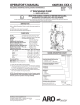
PUMP DATA
Figure 1
Material Inlet
Immersed
Air Inlet (female)
1/4 - 18 N.P.T.F. - 1
MODEL 61204X-X
Material Outlet (female)
3/4 - 14 N.P.T.F. - 1
NOTE: Dimensions are shown in inches and (mm), supplied for reference only and are typically
rounded up to the nearest 1/16 inch.
MODEL “A” (mm) “B” (mm) WEIGHT (kg)
612041-X 54”(1371.6) 34-5/8”(879.5) 13 lb (5.9)
612042-X 64-1/4”(1631.9) 44-7/8”(1139.8) 14 lb (6.4)
“A”
‘‘B’’
48
INGERSOLL RAND COMPANY LTD
209 NORTH MAIN STREET – BRYAN, OHIO 43506
(800) 495-0276 FAX(800) 892-6276
© 2017
CCN 99444598
arozone.com
IMPORTANT
This is one of two documents which support the pump. Replace-
ment copies of these forms are available upon request.
= 612041-X MODEL OPERATOR’S MANUAL
- S-63
2
GENERAL INFORMATION LUBRICATION PISTON PUMPS
x Use only genuine AROR replacement parts to assure compatible
pressure rating and longest service life.
x 637084 for air motor repair (see page 2).
x 637081 for lower pump end (Nitrile) repair (see page 3).
x 637083 for lower pump end (PTFE) repair (see page 3).
RELEASED: 10-23-86
REVISED: 4-21-17
(REV: M)

Page 2 of 4 612041-X
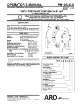
PARTS LIST / AIR MOTOR SECTION
Item Description (size in inches) Qty Part No. [Mtl]
1 Cap (1) 76073-2 [A]
2 Washer (1) 77290 [C]
“O” Ring (3/32” x 2-5/16” o.d.) (1) Y325-138 [B]
4 Spring (1) 77208 [C]
5 Button (1) 90638 [C]
6 Cylinder (1) 76074-2 [A]
Spacer and Piston Assembly (1) 61088
8 Screw (#4 - 40 x 3/8”) (3) Y222-54-C [C]
9 Valve Plate (1) 76090 [C]
10 Piston Assembly (1) 60656 [B/C]
11 Valve Spacer (1) 76856 [D]
Gasket (1) F21-53
[Co]
13 Plunger Tip (1) 77794 [C]
“O” Ring (1/8” x 1-1/4” o.d.) (1) Y325-214 [B]
15 Plunger (1) 76215 [C]
“O” Ring (3/32” x 2-1/16” o.d.) (1) Y325-134 [B]
17 Spring (1) 76070 [C]
18 Pump Body (1) 77807 [A]
“O” Ring (.275” x 1.837” o.d.) (1) 77803 [B]
20 Ground Screw (#10 - 32 x 1/4”)(page 3) (1) 93005 [C]
21 Dowel Pin (3/16” dia. x 1-1/8”) (1) Y148-29 [C]
Parts in Repair Kit 637084
MATERIAL CODE
[A] = Aluminum [CI] = Cast Iron [SS] = Stainless Steel
[B] = Nitrile [Co] = Copper [T] = PTFE
[Br] = Brass [D] = Acetal [U] = Urethane
[C] = Carbon Steel [NY] = Nylon [V] = Viton
1
3
2
4
5
6
8
9
10
11
7
12
13
14
15
17
16
18
19
21
Figure 2
1/4 N.P.T.F. - 1
PUMP DISASSEMBLY
NOTE: All threads are right hand.
1. Place the 2”differential pump in a vise. Rotate the pump so the ma-
terial outlet is resting against the vise jaw. CAUTION:Do notclamp
the pump too tightly.
Figure 3
2. Place a strapwrench aroundthe (1) cap and remove the cap. If the
(6) cylinder comes off with the (1) cap, place the cap in a vise and
use a strap wrench around the (6) cylinder to unscrew it from the
cap. NOTE: Do not squeeze or use a pipe wrench on (6) cylinder.
3. Remove (3) “O”ring.
4. Usinga strapwrench,asshowninfigure 3, unthreadandremove the
(6) cylinder from the (18) pump body.
5. Remove (16) “O”ring from the (18) pump body.
6. Unthread and remove (7) spacerandpiston assembly from the (13)
plunger tip.
7. Remove (12) gasket from (13) plunger tip.
9
Figure 4
10
11
8
35
37
38
22
39
(continued on page 4)
n 3
n 7
n 12
n 14
n 16
n 19
n

Page 3 of 4612041-X
PARTS LIST / LOWER PUMP SECTION
Item Description (size in inches) Qty Part No. [Mtl]
22 Piston Rod (1) 77804 [C]
23 “O” Ring (1/16” x 5/8” o.d.) (1) Y325-14 [B]
24 Plug (1) 79057 [NY]
“O” Ring (3/32” x 2-1/16” o.d.)
models 61204X-1 (1) Y325-134 [B]
models 612041-3 (1) Y327-134 [V]
“O” Ring (3/32” x 1-7/16” o.d.)
models 61204X-1 (1) Y325-124 [B]
models 612041-3 (1) Y327-124 [V]
27 Groove Pin (1/8” dia. x 3/4”) (1) Y122-85 [C]
28 Collar (1) 76900 [C]
29 Washer (models 612041-3 only) (1) 77910 [C]
Packing (models 61204X-1 only) (2) 75649 [U]
“O” Ring (1/16” x 1/2” o.d.)
models 61204X-1 (1) Y325-12 [B]
models 612041-3 (1) Y327-12 [V]
32 Retaining Ring (1) 77801
[C]
Piston models 61204X-1 (1) 75648 [D]
models 612041-3 (1) 77827 [T]
34 Suction Tube models 612041-X (1) 77798 [C]
models 612042-1 (1) 77814 [C]
35 Washer (1) 77797 [C]
36 Tube (1) 77806 [C]
Cup models 61204X-1 (1) 77796 [B]
models 612041-3 (1) 77826 [T]
38 Washer (1) 77800 [C]
39 Nut (3/8” - 24) (1) Y115-14 [SS]
40 Stem (1) 76093 [C]
41 Plate (1) F58-3 [C]
42 Valve Body (1) F259-1 [CI]
43 Foot Valve Asm (includes items 40 - 42) (1) 60657
44 Bung Adapter (includes item 45) (1) 60870 [C]
45 Screw (1/4” - 20 x 1-1/2”) (1) Y197-158-C [C]
48 Needle Valve (see figure 1) (1) 92818 [Br]
20
23
24
22
25
26
34
35
41
42
40
32
31
30
33
28
27
43
37
38
39
36
29 33
612041-3
3/4 N.P.T.F. - 1
Figure 5
- 25
- 26
- 30
- 31
- 33
- 37
- Parts included in 637081 service kit (models 61204X-1).
Parts included in 637083 service kit (models 612041-3).

PN 97999-93
Page 4 of 4 612041-X
PUMP DISASSEMBLY (continued)
NOTE: Perform steps 8 thru 10 only if (7) spacer and piston assembly
needs servicing.
8. Remove the three (8)screwsfromthe (11)valve spacer(see figure 4).
9. Remove the (9) valve plate.
10. Remove the (11) valve spacer from the (10) piston assembly.
11. Unthread(13)plungertipfromthe (15) plungerbyusinga wrenchon
the flatsof the (13) plunger tipand a strap wrench onthe (15) plung-
er. CAUTION:Place the strap wrench on the veryuppermostpartof
the (15) plunger.
12. Remove (14) “O”ring.
13. Remove (21) dowel pin.
14. Remove (13) plunger tip.
15. Remove (15) plunger.
16. Remove (17) spring from the (18) pump body.
17. Remove (19) “O”ring from the (18) pump body.
18. Using a pipe wrench, unthread and remove the (34) suction tube
from the (18) pump body. CAUTION: Place the pipe wrench on the
very uppermost or very lower most part ofthe (34) suction tube. Do
not damage or dent this tube.
19. Remove (25) “O”ring from the (18) pump body.
20. Grasp the (22) piston rod and remove by pulling straight out.
21. Using a strap wrench on (36) tube, unthread and remove from (18)
pump body. CAUTION: Do not damage or dent this tube.
22. Remove (26) “O”ring from (18) pump body.
23. Remove (24) plug and (23) “O”ring.
24. Clampthe(43)intake valve assemblyina vise. Usinga strapwrench
on (34) suction tube, unthread and remove from valve assembly.
CAUTION: Do not damage or dent this tube.
25. Usinga wrenchonflatsof(22)pistonrod, unthreadandremove (39)
nut (see figure 4).
26. Remove (38) washer, (37) cupand(35)washerfrom(22) pistonrod.
27. Remove (32) retaining ring from the (22) pistonrod, using retaining
ring pliers.
28. Remove (33) piston from (22) piston rod.
29. Remove two (30) packings (where applicable).
30. Remove (31) “O”ring from (22) piston rod.
NOTE: Do not remove (27) groove pin and (28) collar from (22) piston
rod unless damage is evident. Remove (27) groove pin, releasing (28)
collar.
PUMP REASSEMBLY
1. Insertthe (11) valve spacerthruthe bottomofthe(10) pistonassem-
bly (see figure 4).
2. Place the (9) valve plate on topofthe (10) piston assembly, aligning
the three holes with the posts of (11) valve spacer.
3. Fasten the (9) valve plate down usingthe three (8) screws. Lay this
assembly aside for the moment.
4. Place the (28) collar on the (22) piston rod and secure with (27)
groove pin.
5. Assemble (29) washer next to (28) collar on (22) piston rod.
6. Grease and assemble (31) “O”ring to (22) piston rod.
7. Assemble two (30) packings to (33) piston (where applicable).
8. Assemble (33) piston to (22) pistonrod, securing with (32) retaining
ring.
9. Assemble (35) washer, (37) cup (lips up) and (38) washer onto (22)
piston rod, securing with (39) nut (see figure 4).
10. Grease and assemble (23) “O” ring into (24) plug and screw (24)
plug into (18) pump body.
11. Place the (18) pumpbodyina viseandrotateitsothe materialoutlet
is resting against the vise jaw. CAUTION: Do not clamp the pump
body too tightly.
12. Grease and assemble (26) “O”ring to (18) pump body.
13. Thread (36) tube onto (18) pump body and tighten, using a strap
wrench.
14. Assemble the (22) piston rod up thru the (18) pump body.
15. Grease and assemble (25) “O”ring to (18) pump body.
16. Threadthe (34) suction tube to the (18) pumpbodyandtighten, us-
ing a strap wrench.
17. Thread the (43) intake valve assembly to the (34) suction tube and
tighten.
18. Grease and assemble (19) “O”ring into (18) pump body.
19. Place (17) spring into (18) pump body.
20. Assemble (15) plunger over (22) piston rod.
21. Assemble (13) plungertipto(22)pistonrodandinsert(21) dowelpin
to secure plunger tip.
22. Grease and assemble (14) “O”ring to (13) plunger tip.
23. Pull(15) plungerup and thread(13) plunger tip to plungerandtight-
en by using a wrench onflats of (13) plungertip and a strap wrench
on (15) plunger.
24. Place the (12) gasket over the end of (13) plunger tip.
25. Threadthe (7) spacer andpistonassembly ontothe (13) plungertip
and tighten.
26. Grease and assemble (16) “O”ring to (18) pump body.
27. Thoroughly grease the inside of the (6) cylinder and assemble over
the (7) spacer and piston assembly, threading onto the (18) pump
body.
28. Assemble (2) washer, (3) “O”ring, (4) spring and (5) button into (1)
capandassemble capto(6) cylinder, tighteningusinga strapwrench.
TROUBLE SHOOTING
Pump continually cycles.
x Check for empty material supply. Disconnect the air (from the pump)
replenish material supply.
x Check for worn or damaged (30) packing or (33) piston.
Material on one stroke only (fast downstroke).
x The intake valve assembly may not be checking or sealing properly.
Remove the intake valve assembly and inspect. If the valve assem-
bly is damaged, replace with new parts. If the valve assembly is not
damaged, thoroughly clean and reassemble to the pump (see pump
instructions).
Material on one stroke only (fast upstroke).
x Check for worn or damaged (37) cup. Replace cup (see pump
instructions and figure 4).
Material leakage out the top of the pump body.
x Check for worn or damaged (30) packing or (33) piston.
Air leakage out of the exhaust holes. (See Air Motor Instructions)
x Check to see if the (9) valve plate is loose or has become disas-
sembled from the (11) valve spacer.
x Check for worn or damaged (10) piston assembly.
x Check for worn or warped (9) valve plate.
x Worn or damaged (14) “O” ring. Replace (14) “O’’ ring.
/