Retracta Retracta GR100 User manual

Type
User manual
RP32ML Issue 13 © 2014 Page 1 of 20
INSTRUCTION MANUAL FOR ALL MODELS
(Excluding OXY-ACETYLENE and OXY-LPG)
Introduction
Thank you for purchasing a Macnaught Retracta Hose
Reel. This product is manufactured from the highest quality
materials and will provide many years of reliable service
when maintained and operated correctly. Your Retracta
Hose Reel has a guaranteed Spare Parts Availability for 10
years.
1 x Retracta Hose Reel.
1 x BU100 Mounting Bracket.
1 x Accessory Bag containing:
(Instruction Manual, Locking Bracket, Handle,
2 x 15mm screws, 1 x Metal Screw)
Other accessories may be included depending on model
IMPORTANT!
Please read this safety information carefully
and refer to the Parts Diagram before use.
Read and retain this instruction manual to assist you in
the correct installation, operation and maintenance of this
product.
Follow all safety instructions. Where CAUTION! is
shown this signifies the risk of personal injury or damage
to property that may be caused by incorrect use of this
product.
Ensure that all operators are aware of the correct
operating and maintenance procedures for this product.
DO NOT attempt to open the drum assembly (item 5) for
any reason. If the spring is damaged a new drum assem-
bly must be installed.
DO NOT exceed the maximum working pressure shown on
the product label.
DO NOT use this product for any other purpose than as
shown on the product label or modify this product in any
way.
ALWAYS use genuine Retracta spare parts when
maintaining this product.
A) Using 2 x 15mm screws (supplied) attach the carrying
handle to the top of the reel.
B) The BU100 mounting bracket (supplied) is suitable for
installing the reel up to 1.8mtrs high on a wall or up to
4.5mtrs overhead (see Figures 1 and 2). This bracket al-
lows the reel to swivel in the direction of use. To prevent
the reel from swiveling in the overhead position (figure 2)
only install the locking bracket RB9 (supplied).
C) Use the optional BB100 bracket to install the reel be-
tween 1.8mtrs and 4.5mtrs on a wall or on a bench/floor
(see figures 3 and 4).
D) Fix the mounting bracket in the desired location using
appropriate fixings (not supplied).
E) BU100 remove the pin from the bracket, mount the
reel onto the bracket and insert the pin to secure the reel.
F) BB100 – Remove the upper collar by loosening the
screw, mount the reel onto the bracket, refit the collar and
secure with the screw.
H) The connecting hose should allow the reel to swivel
freely on the bracket.
G) Use the 8mm screw provided to secure the pin on the
BU100 bracket and prevent accidental removal. A padlock
(not supplied) can be fitted for additional security on both
brackets.
Installation Procedure
Fig.1 BU100 - Wall Fig.2 BU100 - Overhead
Fig.3 BB100 - Floor/Bench Fig.4 BB100 - High Wall
Auto-Rewind Hose Reels
Carton Contents
Includes models
AB100 (AB2101), AR100 (AR2101)
AR200 (AR2121), AW100 (AW2101)
AW150 (AW2150), AW200 (AW2121)
CW100 (CW2121), DR100 (DR2121)
FG100 (FG2106), GR100 (GR2061)
HW100 (HW2121), HWP100 (HWP2101)
OLP100 (OLP2121), OMP100 (OMP2101)
WP100 (WP2101)
RP32ML Issue 13 © 2014 Page 2 of 20
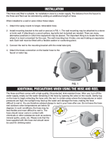
Use a suitable flexible hose and fittings (not supplied) to
connect the reel to the supply
DO NOT use a rigid pipe. Inlet connections: GR models
¼”BSPF. DR models supplied with connecting hose
¾”BSPF. All other models 3/8"BSPF.
I) An isolating valve should be installed on the supply to
allow the reel to be serviced.
Slowly open the supply valve and inspect the reel for
leaks.
A) Pull the hose out to the required length.
B) A series of clicks will be heard every half revolution of
the drum.
C) To lock the hose, release it slowly on the 1st, 2nd or 3rd
click.
To prevent injury or damage do not release
the hose during rewinding.
D) To rewind the hose pull the hose slowly until the clicking
stops, release the hose and allow it to rewind under control
until the hose stopper (part 14) rests against the reel
mouth.
Always isolate the reel from the supply before commencing
maintenance.
Always test the reel for leaks and correct
operation after maintenance.
Procedure 1: Removal / Replacement of Inlet Side
Plate, Swivel and Swivel Seals (parts 1, 2, 3 & 4)
A) Pull the hose out until it is fully extended and latch the
hose.
B) Place reel on a bench with the inlet side plate (part 1)
facing up.
C) Remove the screw located at the edge of the inlet side
plate
.
D) Rotate plate clockwise to remove the swivel assembly
and hose are attached.
E) Remove circlip from the end of the shaft (part 4) and
slide the swivel body (part 3) from the shaft (part 2).
F) If necessary release the shaft (part 2) by removing the
two screws securing it to the inlet side plate (part 1).
G) Remove the O-Rings from the shaft (part 2).
Do not damage the shaft or swivel body when removing or
installing O-Rings.
H) Check that the shaft and swivel are clean before fitting
new O-Rings.
I) Slide swivel body onto shaft and replace circlip.
J) If necessary refit the shaft onto the inlet side plate by
replacing the two screws.
K) To replace the inlet side plate, brace the reel between
your body and the edge of a bench, reposition the side
plate ensuring that the swivel shaft (part 2) is located in
the drum (part 5) and turn counter clockwise to lock.
Replace the side screw.
Procedure 2: Hose Replacement (item 13)
A) Follow the instructions given in Procedure 1 for
Removing the Inlet Side Plate.
B) Remove the hose from the swivel (part 3) and remove
the hose stoppers (part 14) from both ends of the hose.
C) Pull the hose out from the mouth of the reel.
D) Feed the hose through the mouth of the reel and into
the drum.
E) Fit the hose stopper 12cm from the end of the hose.
F) Connect the hose to the swivel (item 3).
H) Fit the hose stopper (part 14) to the end of the hose.
I) Rewind the hose onto the reel.
J) If required adjust the spring tension (see Procedure 3).
Procedure 3: Spring Tension Adjustment, Latching
Plate, Tension Plate and Ratchet Plate Removal / Re-
placement (items 8, 9 & 10).
Ensure that the hose is fully rewound and that the hose
stopper is resting against the reel.
A) Place the reel on a bench with the latching plate (part 9)
facing up.
B) Open the centre of the tension plate (part 8) and place
the handles of a pair of pliers in the slots.
C) Holding the pliers firmly release the two screws secur-
ing the tension plate and carefully allow the tension plate
to slowly unwind counter-clockwise until no further pres-
sure is felt.
D) Remove the screw in the centre of the tension plate and
remove the tension plate.
E) Remove the screw on the edge of the latching plate and
turn clockwise to remove.
Latching and Rewinding Operation
Maintenance Procedures
CAUTION
CAUTION
CAUTION
CAUTION
CAUTION
CAUTION
CAUTION
RP32ML Issue 13 © 2014 Page 3 of 20
Procedure 4: Drum Assembly and Outer Case
Replacement (parts 5, 6 & 7)
A) Follow the instructions given in Procedures 1, 2 & 3 to
remove the inlet side plate, hose, latching plate and
tension plate.
B) Undo the nut and bolt sets that secure the two parts of
the outer case (parts 6 & 7) and pull apart.
C) Remove drum assembly (part 5) and replace if
necessary.
D) With the drum assembly in place push the two parts of
the outer case together and secure using the nut and bolt
sets. Ensure that the steel mouth guard is at the top of the
reel.
E) Follow the instructions given in Procedures 1, 2 & 3 to
refit the inlet side plate, hose, latching plate and tension
plate.
Troubleshooting Guide
F) To remove the ratchet plates (part 10) remove the se-
curing screws. Fit new ratchet plates in the same positions.
G) To replace the latching plate, hold the reel between
your body and the edge of a bench. Reposition the latching
plate and turn counter-clockwise to lock. Replace the side
screw.
H) Replace the tension plate and secure with the central
screw.
I) Insert the handles of a pair of pliers into the slots on the
tension plate and turn clockwise until the hose stopper
rests against the reel.
J) Turn the tension plate for 6 complete revolutions keep-
ing a firm grip on the pliers.
K) Line up the screw holes on the tension plate with the
marks on the latching plate and secure the two screws.
Close the centre of the tension plate.
Symptom Remedy
Hose jams in reel Pull hose out and guide hose on rewind.
Hose will not rewind Refer to instructions for correct rewinding operation.
Adjust spring tension.
Hose too heavy Incorrect hose fitted
Fit correct Macnaught hose assembly.
Reel will not latch Refer to instructions for correct latching operation.
Replace latching side plate and/or ratchet plates.
Reel leaks Check all connections and fittings.
RP32ML Issue 13 © 2014 Page 15 of 20
Notes
RP32ML Issue 13 © 2014 Page 16 of 20
Spare Part Diagram
Diagram of Hose Reel AR100 (AR2101).
Layout varies depending on model.
Use this diagram as a guide.
Swivel / Hose Assembly
Latching Plate Assembly Details
GR100
AB100
HW100
HWP100
OLP100
OMP100
PLASTIC SLEEVE
SPRING
LATCH PAWL
LATCHING PLATE
7
1
9
4
11
13
2
5
6
3
8
10
14
2
12
13
12
2
15
16 17
14
3
13
4
13
3
4
2
RP32ML Issue 13 © 2014 Page 17 of 20
Spare Part List
Item
Description
AB100
AR100
AR200
AW150
AW100
1 Inlet side plate order RP34s order RP34s order RP34s order RP34s order RP34s
2 Swivel Shaft RS27s (NPT) RS48s (NPT) RS27s (NPT) RS27s (NPT)
3 Swivel body RS100s (BSP) RS26s (BSP) RS46s (BSP) RS26s (BSP) RS26s (BSP)
4 Circlip
5 Drum assembly RP35-Black RP35-Black RP35-Black RP35-Black RP35-Black
6 Outer case assembly RP36Cs* RP36Cs* RP36Cs* RP36Cs* RP36Cs*
7 Outer case - plain
8 Tension plate assembly RP114A-Blacks RP114A-Blacks RP114A-Blacks RP114A-Blacks RP114A-Blacks
9 Latching plate assembly Order - RP34s Order - RP34s Order - RP34s Order - RP34s Order - RP34s
10 Latching plate (for comp set) (for comp set) (for comp set) (for comp set) (for comp set)
11 Carry handle order RP36Cs* order RP36Cs* order RP36Cs* order RP36Cs* order RP36Cs*
12 Seal set BS115VS BS115VS BS115VS BS115VS BS115VS
13 Hose assembly kit RH99s (BSP) RH35s (BSP) RH22s (BSP) RH61s (BSP) RH86s (BSP)
(Inc hose stopper) RH101s (NPT) RH36s (NPT) RH17S (NPT) RH15s (NPT) RH74s (NPT)
14 Hose stopper Z10s Z10s Z40s Z10s Z10s
15 Inlet swivel assembly N/A N/A N/A N/A N/A
16 inlet adapter N/A N/A N/A N/A N/A
17 Bearing set (incl screws) N/A N/A N/A N/A N/A
18 Nozzle set N/A N/A N/A N/A N/A
Locking baracket order BU100 order BU100 order BU100 order BU100 order BU100
Std wall bracket BU100 incl RB9s BU100 incl RB9s BU100 incl RB9s BU100 incl RB9s BU100 incl RB9s
Feeder hose assy N/A N/A N/A N/A N/A
Item
Description
AW200
CW100
DR100
FG100
GR100
1 Inlet side plate order RP34s order RP34s order RP34s order RP34s order RP34s
2 Swivel Shaft RS48s (NPT) RS48s (NPT) RS27s (NPT) RS44s (NPT)
3 Swivel body RS46s (BSP) RS46s (BSP) RS1s RS26s (BSP) RS43s (BSP)
4 Circlip
5 Drum assembly RP35-Black RP35-Black RP35-Black RP35-Black RP35-Black
6 Outer case assembly RP36Cs* RP36Cs* RP36Cs* RP36Cs* RP36Cs*
7 Outer case - plain
8 Tension plate assembly RP114A-Blacks RP114A-Blacks RP114A-Blacks RP114A-Blacks RP114A-Blacks
9 Latching plate assembly Order - RP34s Order - RP34s Order - RP34s Order - RP34s Order - RP34s
10 Latching plate (for comp set) (for comp set) (for comp set) (for comp set) (for comp set)
11 Carry handle order RP36Cs* order RP36Cs* order RP36Cs* order RP36Cs* order RP36Cs*
12 Seal set BS115VS BS115VS BS115VS BS115VS
13 Hose assembly kit RH83s (BSP) RH40s (BSP) RH3s RH140s (BSP) RH45s (BSP)
(Inc hose stopper) RH87s (NPT) RH44S (NPT) RH49S (NPT)
14 Hose stopper Z40s Z40s Z10s Z10s Z10s
15 Inlet swivel assembly N/A N/A N/A N/A SB6s
16 inlet adapter N/A N/A N/A N/A RS40s
17 Bearing set (incl screws) N/A N/A N/A N/A RS36s
18 Nozzle set N/A RH51s N/A N/A N/A
Locking baracket order BU100 order BU100 order BU100 order BU100 order BU100
Std wall bracket BU100 incl RB9s BU100 incl RB9s BU100 incl RB9s BU100 incl RB9s BU100 incl RB9s
Item
Description
HW100
HWP100
OLP100
OMP100
WP100
1 Inlet side plate order RP34s order RP34s order RP34s order RP34s order RP34s
2 Swivel Shaft RS52s (NPT) RS90s (NPT) RS51s (NPT) RS51s (NPT) RS68s (NPT)
3 Swivel body RS64s (BSP) RS85s (BSP) RS50s (BSP) RS50s (BSP) RS67s (BSP)
4 Circlip
5 Drum assembly RP35-Black RP35-Black RP35-Black RP35-Black RP43-Black
6 Outer case assembly RP36Cs* RP36Cs* RP36Cs* RP36Cs* RP36Cs*
7 Outer case - plain
8 Tension plate assembly RP114A-Blacks RP114A-Blacks RP114A-Blacks RP114A-Blacks RP114A-Blacks
9 Latching plate assembly Order - RP34s Order - RP34s Order - RP34s Order - RP34s Order - RP34s
10 Latching plate (for comp set) (for comp set) (for comp set) (for comp set) (for comp set)
11 Carry handle order RP36Cs* order RP36Cs* order RP36Cs* order RP36Cs* order RP36Cs*
12 Seal set BS115Es RS85s (BSP) BS115Vs BS115Vs BS115Vs
RS90s (NPT)
13 Hose assembly kit RH41s (BSP) RH64s (BSP) RH81s (BSP) RH84s (BSP) RH50s (BSP)
(Inc hose stopper) RH46s (NPT) RH82s (NPT) RH85S (NPT) RH63s (NPT)
14 Hose stopper Z40s Z10s Z40s Z40s Z10s
15 Inlet swivel assembly N/A N/A N/A N/A N/A
16 inlet adapter N/A N/A N/A N/A N/A
17 Bearing set (incl screws) N/A N/A N/A N/A N/A
18 Nozzle set N/A N/A N/A N/A N/A
Locking baracket order BU100 order BU100 order BU100 order BU100 order BU100
Std wall bracket BU100 incl RB9s BU100 incl RB9s BU100 incl RB9s BU100 incl RB9s BU100 incl RB9s
RP32ML Issue 13 © 2014 Page 19 of 20
Notes
RP32ML Issue 13 © 2014 Page 20 of 20
For Warranty Terms and Conditions see macnaught.com.au
For a list of Australian Service Centres see macnaught.com.au
  • Page 1 1
  • Page 2 2
  • Page 3 3
  • Page 4 4
  • Page 5 5
  • Page 6 6
  • Page 7 7
  • Page 8 8
  • Page 9 9
  • Page 10 10
  • Page 11 11
  • Page 12 12
  • Page 13 13
  • Page 14 14
  • Page 15 15
  • Page 16 16
  • Page 17 17
  • Page 18 18
  • Page 19 19
  • Page 20 20

Retracta Retracta GR100 User manual

Type
User manual

Ask a question and I''ll find the answer in the document

Finding information in a document is now easier with AI