Proware EP-3164S1/D1-G1S3 User manual
- Category
- Server barebones
- Type
- User manual
This manual is also suitable for

iSCSI GbE to SAS/SATA II
RAID Subsystem
User Manual
Revision 1.0

iSCSI GbE to SAS/SATA II RAID Subsystem
2
User Manual
Table of Contents
Preface ................................................................................................................................ 6
Before You Begin ............................................................................................................. 7
Safety Guidelines ............................................................................................................................................................ 7
Controller Configurations ........................................................................................................................................... 7
Packaging, Shipment and Delivery ...................................................................................................................... 7
Chapter 1 Introduction ................................................................................................. 9
1.1 Technical Specifications ...................................................................................................................................... 11
1.2 Terminology ............................................................................................................................................................ 13
1.3 RAID Levels .............................................................................................................................................................. 15
1.4 Volume Relationship Diagram ......................................................................................................................... 16
Chapter 2 Identifying Parts of the RAID Subsystem ........................................... 17
2.1 Main Components ................................................................................................................................................ 17
2.1.2 Front View ........................................................................................................................................................ 17
2.1.2.1 Disk Trays ................................................................................................................................................. 18
2.1.2.2 LCD Front Panel ..................................................................................................................................... 19
2.1.2 Rear View ......................................................................................................................................................... 21
2.2 Controller Module ................................................................................................................................................ 22
2.2.1 Controller Module Panel ............................................................................................................................ 23
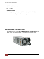
2.3 Power Supply / Fan Module (PSFM) ............................................................................................................. 24
2.3.1 PSFM Panel ...................................................................................................................................................... 25
2.4 Checklist before Starting ................................................................................................................................... 26
Chapter 3 Getting Started with the Subsystem .................................................... 28
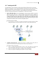
3.1 Connecting the iSCSI RAID Subsystem to the Network ....................................................................... 28
3.2 Powering On ........................................................................................................................................................... 28
3.3 Disk Drive Installation ......................................................................................................................................... 29
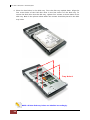
3.3.1 Installing a SAS Disk Drive in a Disk Tray .......................................................................................... 29
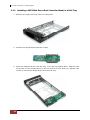
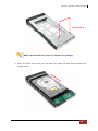
3.3.2 Installing a SATA Disk Drive (Dual Controller Mode) in a Disk Tray ...................................... 32
3.4 iSCSI Introduction ................................................................................................................................................. 35
Chapter 4 Quick Setup ............................................................................................... 37

iSCSI GbE to SAS/SATA II RAID Subsystem
User Manual
3
4.1 Management Interfaces ...................................................................................................................................... 37
4.1.1 Serial Console Port ....................................................................................................................................... 37
4.1.2 Remote Control – Secure Shell ............................................................................................................... 37
4.1.3 LCD Control Module (LCM) ...................................................................................................................... 38
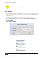
4.1.4 Web GUI ........................................................................................................................................................... 40
4.2 How to Use the System Quickly ..................................................................................................................... 42
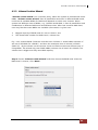
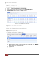
4.2.1 Quick Installation .......................................................................................................................................... 42
4.2.2 Volume Creation Wizard ............................................................................................................................ 45
Chapter 5 Configuration ............................................................................................ 47
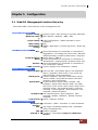
5.1 Web GUI Management Interface Hierarchy ............................................................................................... 47
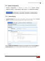
5.2 System Configuration .......................................................................................................................................... 49
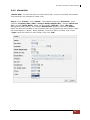
5.2.1 System Setting ............................................................................................................................................... 49
5.2.2 Network Setting ............................................................................................................................................. 50
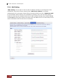
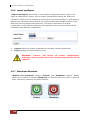
5.2.3 Login Setting ................................................................................................................................................... 51
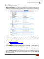
5.2.4 Mail Setting ..................................................................................................................................................... 52
5.2.5 Notification Setting ...................................................................................................................................... 53
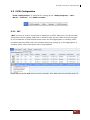
5.3 iSCSI Configuration .............................................................................................................................................. 55
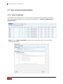
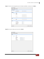
5.3.1 NIC ...................................................................................................................................................................... 55
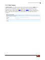
5.3.2 Entity Property ................................................................................................................................................ 59
5.3.3 Node ................................................................................................................................................................... 60
5.3.4 Session ............................................................................................................................................................... 63
5.3.5 CHAP Account ................................................................................................................................................ 64
5.4 Volume Configuration ......................................................................................................................................... 65
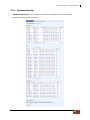
5.4.1 Physical Disk .................................................................................................................................................... 65
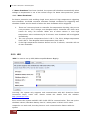
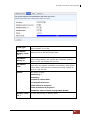
5.4.2 RAID Group ..................................................................................................................................................... 68
5.4.3 Virtual Disk....................................................................................................................................................... 71
5.4.4 Snapshot ........................................................................................................................................................... 75
5.4.5 Logical Unit ...................................................................................................................................................... 78
5.4.6 Example ............................................................................................................................................................. 79
5.5 Enclosure Management ...................................................................................................................................... 84
5.5.1 Hardware Monitor ........................................................................................................................................ 85
5.5.2 UPS ...................................................................................................................................................................... 86
5.5.3 SES ....................................................................................................................................................................... 88

iSCSI GbE to SAS/SATA II RAID Subsystem
4
User Manual
5.5.4 Hard Drive S.M.A.R.T. Support ................................................................................................................. 88
5.6 System Maintenance ........................................................................................................................................... 90
5.6.1 System Information ...................................................................................................................................... 90
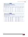
5.6.2 Event Log .......................................................................................................................................................... 91
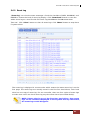
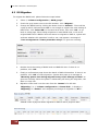
5.6.3 Upgrade ............................................................................................................................................................ 92
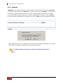
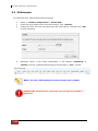
5.6.4 Firmware Synchronization ......................................................................................................................... 93
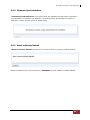
5.6.5 Reset to Factory Default ............................................................................................................................ 93
5.6.6 Import and Export ........................................................................................................................................ 94
5.6.7 Reboot and Shutdown ................................................................................................................................ 94
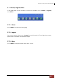
5.7 Home/Logout/Mute ............................................................................................................................................. 95
5.7.1 Home ................................................................................................................................................................. 95
5.7.2 Logout ............................................................................................................................................................... 95
5.7.3 Mute ................................................................................................................................................................... 95
Chapter 6 Advanced Operations .............................................................................. 96
6.1 Volume Rebuild ..................................................................................................................................................... 96
6.2 RG Migration........................................................................................................................................................... 98
6.3 VD Extension ......................................................................................................................................................... 100
6.4 Snapshot / Rollback ........................................................................................................................................... 101
6.4.1 Create Snapshot Volume ......................................................................................................................... 102
6.4.2 Auto Snapshot.............................................................................................................................................. 104
6.4.3 Rollback ........................................................................................................................................................... 105
6.5 Disk Roaming........................................................................................................................................................ 106
6.6 VD Clone ................................................................................................................................................................ 106
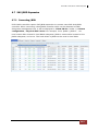
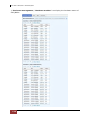
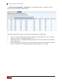
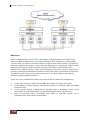
6.7 SAS JBOD Expansion ......................................................................................................................................... 113
6.7.1 Connecting JBOD ........................................................................................................................................ 113
6.8 MPIO and MC/S .................................................................................................................................................. 117
6.9 Trunking and LACP ............................................................................................................................................. 119
6.10 Dual Controllers ................................................................................................................................................ 121
6.10.1 Perform I/O ................................................................................................................................................. 121
6.10.2 Ownership .................................................................................................................................................... 122
6.10.3 Controller Status ....................................................................................................................................... 122
6.11 QReplica (Optional) ......................................................................................................................................... 124

iSCSI GbE to SAS/SATA II RAID Subsystem
User Manual
5
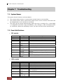
Chapter 7 Troubleshooting .................................................................................... 134
7.1 System Buzzer ...................................................................................................................................................... 134
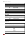
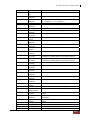
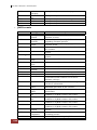
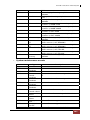
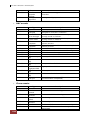
7.2 Event Notifications ............................................................................................................................................. 134
Appendix ....................................................................................................................... 144
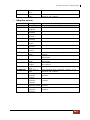
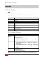
A. Certification list ...................................................................................................................................................... 144
B. Microsoft iSCSI initiator ...................................................................................................................................... 148

iSCSI GbE to SAS/SATA II RAID Subsystem
6
User Manual
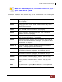
Preface
About this manual
This manual provides information regarding the quick installation and hardware
features of the RAID subsystem. This document also describes how to use the
storage management software. Information contained in the manual has been
reviewed for accuracy, but not for product warranty because of the various
environment/OS/settings. Information and specifications will be changed without
further notice.
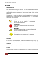
This manual uses section numbering for every topics being discussed for easy and
convenient way of finding information in accordance with the user’s needs. The
following icons are being used for some details and information to be considered in
going through with this manual:
Copyright
No part of this publication may be reproduced, stored in a retrieval system, or
transmitted in any form or by any means, electronic, mechanical, photocopying,
recording or otherwise, without the prior written consent.
Trademarks
All products and trade names used in this document are trademarks or registered
trademarks of their respective holders.
Changes
The material in this document is for information only and is subject to change without
notice.
IMPORTANT!
These are the important information that the user must
remember.
WARNING!
These are the warnings that the user must follow to avoid
unnecessary errors and bodily injury during hardware and
software operation of the subsystem.
CAUTION:
These are the cautions that user must be aware to
prevent damage to the equipment and its components.
NOTES:
These are notes that contain useful information and tips
that the user must give attention to in going through
with the subsystem operation.

iSCSI GbE to SAS/SATA II RAID Subsystem
User Manual
7
Before You Begin
Before going through with this manual, you should read and focus to the following
safety guidelines. Notes about the subsystem’s controller configuration and the
product packaging and delivery are also included.
Safety Guidelines
To provide reasonable protection against any harm on the part of the user and to
obtain maximum performance, user is advised to be aware of the following safety
guidelines particularly in handling hardware components:
Upon receiving of the product:
Place the product in its proper location.
To avoid unnecessary dropping out, make sure that somebody is around for
immediate assistance.
It should be handled with care to avoid dropping that may cause damage to the
product. Always use the correct lifting procedures.
Upon installing of the product:
Ambient temperature is very important for the installation site. It must not
exceed 30
◦
C. Due to seasonal climate changes; regulate the installation site
temperature making it not to exceed the allowed ambient temperature.
Before plugging-in any power cords, cables and connectors, make sure that the
power switches are turned off. Disconnect first any power connection if the power
supply module is being removed from the enclosure.
Outlets must be accessible to the equipment.
All external connections should be made using shielded cables and as much as
possible should not be performed by bare hand. Using anti-static hand gloves is
recommended.
In installing each component, secure all the mounting screws and locks. Make
sure that all screws are fully tightened. Follow correctly all the listed procedures
in this manual for reliable performance.
Controller Configurations
This RAID subsystem supports single controller configuration.
Packaging, Shipment and Delivery
Before removing the subsystem from the shipping carton, you should visually
inspect the physical condition of the shipping carton.
Unpack the subsystem and verify that the contents of the shipping carton are all
there and in good condition.
Exterior damage to the shipping carton may indicate that the contents of the
carton are damaged.
If any damage is found, do not remove the components; contact the dealer where
you purchased the subsystem for further instructions.

iSCSI GbE to SAS/SATA II RAID Subsystem
8
User Manual
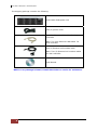
The shipping package contains the following:
NOTE: If any damage is found, contact the dealer or vendor for assistance.
iSCSI RAID Subsystem Unit
Two (2) power cords
Five (5) Ethernet LAN cables for single
controller
Note: Ten (10) Ethernet LAN cables for
dual controller
One (1) External null modem cable
Note: Two (2) External null modem cables
for dual controller
User Manual

iSCSI GbE to SAS/SATA II RAID Subsystem
User Manual
9
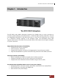
Chapter 1 Introduction
The iSCSI RAID Subsystem
The EP-3164 series RAID subsystem features four Gigabit ports on each controller to
increase system efficiency and performance. It features high capacity expansion, with 16
hot-swappable SAS/SATA II hard disk drive bays in a 19-inch 3U rackmount unit, scaling
to a maximum storage capacity in the terabyte range. The EP-3164D series also
supports Dual-active controllers which provide better fault tolerance and higher reliability
of system operation.
Unparalleled Performance & Reliability
Supports Dual-active controllers
Front-end 4/8 x 1Gb iSCSI
Supports 802.3ad port trunking, Link Aggregation Control Protocol (LACP)
High data bandwidth of system architecture by powerful 64-bit RAID processor
Unsurpassed Data Availability
RAID 6 capability provides the highest level of data protection
Supports snapshot-on-the-box w/o relying on host software
Supports Microsoft Windows Volume Shadow Copy Services (VSS)
Exceptional Manageability Menu-driven front panel display
Management GUI via serial console, SSH telnet, Web and secure web(HTTPS)
Event notification via Email and SNMP trap
Menu-driven front panel display

iSCSI GbE to SAS/SATA II RAID Subsystem
10
User Manual
Features
Front-end 4/8 x 1Gb ports support independent access, fail-over and load-
balancing
(802.3ad port trunking, LACP)
Supports iSCSI jumbo frame
Supports Microsoft Multipath I/O (MPIO)
Supports RAID levels 0, 1, 0+1, 3, 5, 6, 10, 30, 50, 60 and JBOD
Local N-way mirror: Extension to RAID 1 level, N copies of the disk
Global and dedicated hot spare disks
Write-through or write-back cache policy for different application usage
Supports greater than 2TB per volume set (64-bit LBA support)
Supports manual or scheduling volume snapshot (up to 32 snapshot)
Snapshot rollback mechanism
On-line volume migration with no system down-time
Online volume expansion
Instant RAID volume availability and background initialization
Supports S.M.A.R.T, NCQ and OOB Staggered Spin-up capable drives

iSCSI GbE to SAS/SATA II RAID Subsystem
User Manual
11
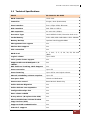
1.1 Technical Specifications
Model EP-3164S1/D1-G1S3
RAID Controller iSCSI-SAS
Controller Single / Dual (Redundant)
Host Interface Four / Eight 1Gb/s Ethernet
Disk Interface SAS 3Gb or SATA II
SAS expansion 4x mini SAS (3Gb/s)
Processor Type Intel IOP342 64-bit (Chevelon dual core)
Cache Memory 2GB~4GB /4GB~8GB DDR-II ECC SDRAM
Battery Backup Optional Hot Pluggable BBM
Management Port support Yes
Monitor Port support Yes
UPS connection Yes
RAID level
0, 1, 0+1, 3, 5, 6, 10, 30, 50, 60 and
JBOD
Logical volume Up to 1024
iSCSI Jumbo frame support Yes
Supports Microsoft Multipath I/O
(MPIO)
Yes
802.3ad Port Trunking, LACP Support Yes
Host connection Up to 32
Host clustering Up to 16 for one logical volume
Manual/scheduling volume snapshot Up to 32
Hot spare disks Global and dedicated
Host access control Read-Write & Read-Only
Online Volume Migration Yes
Online Volume sets expansion Yes
Configurable stripe size Yes
Auto volume rebuild Yes
N-way mirror (N copies of the disk) Yes
Microsoft Windows Volume Shadow
Copy Services (VSS)
Yes
Supports CHAP authentication Yes
S.M.A.R.T. support Yes

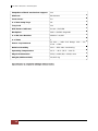
iSCSI GbE to SAS/SATA II RAID Subsystem
12
User Manual
Snapshot rollback mechanism support Yes
Platform Rackmount
Form Factor 3U
# of Hot Swap Trays 16
Tray Lock Yes
Disk Status Indicator Access / Fail LED
Backplane SAS2 / SATA3 Single BP
# of PS/Fan Modules 460W x 2 w/PFC
# of Fans 2
Power requirements
AC 90V ~ 264V Full Range, 10A ~ 5A,
47Hz ~ 63Hz
Relative Humidity 10% ~ 85% Non-condensing
Operating Temperature 10°C ~ 40°C (50°F ~ 104°F)
Physical Dimension 555(L) x 482(W) x 131(H) mm
Weight (Without Disk) 19/20.5 Kg
Specification is subject to change without notice.

iSCSI GbE to SAS/SATA II RAID Subsystem
User Manual
13
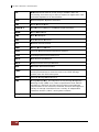
1.2 Terminology
The document uses the following terms:
RAID Redundant Array of Independent Disks. There are different
RAID levels with different degree of data protection, data
availability, and performance to host environment.
PD The Physical Disk belongs to the member disk of one specific
RAID group.
RG Raid Group. A collection of removable media. One RG consists
of a set of VDs and owns one RAID level attribute.
VD Virtual Disk. Each RD could be divided into several VDs. The
VDs from one RG have the same RAID level, but may have
different volume capacity.
LUN Logical Unit Number. A logical unit number (LUN) is a unique
identifier which enables it to differentiate among separate
devices (each one is a logical unit).
GUI Graphic User Interface.
RAID cell When creating a RAID group with a compound RAID level, such
as 10, 30, 50 and 60, this field indicates the number of
subgroups in the RAID group. For example, 8 disks can be
grouped into a RAID group of RAID 10 with 2 cells, 4 cells. In
the 2-cell case, PD {0, 1, 2, 3} forms one RAID 1 subgroup and
PD {4, 5, 6, 7} forms another RAID 1 subgroup. In the 4-cells,
the 4 subgroups are PD {0, 1}, PD {2, 3}, PD {4, 5} and PD
{6,7}.
WT Write-Through cache-write policy. A caching technique in which
the completion of a write request is not signaled until data is
safely stored in non-volatile media. Each data is synchronized in
both data cache and accessed physical disks.
WB Write-Back cache-write policy. A caching technique in which the
completion of a write request is signaled as soon as the data is
in cache and actual writing to non-volatile media occurs at a
later time. It speeds up system write performance but needs to
bear the risk where data may be inconsistent between data
cache and the physical disks in one short time interval.
RO Set the volume to be Read-Only.
DS Dedicated Spare disks. The spare disks are only used by one
specific RG. Others could not use these dedicated spare disks
for any rebuilding purpose.
GS Global Spare disks. GS is shared for rebuilding purpose. If some
RGs need to use the global spare disks for rebuilding, they could
get the spare disks out from the common spare disks pool for
such requirement.

iSCSI GbE to SAS/SATA II RAID Subsystem
14
User Manual
DG DeGraded mode. Not all of the array’s member disks are
functioning, but the array is able to respond to application read
and write requests to its virtual disks.
SCSI Small Computer Systems Interface.
SAS Serial Attached SCSI.
S.M.A.R.T. Self-Monitoring Analysis and Reporting Technology.
WWN World Wide Name.
HBA Host Bus Adapter.
SES SCSI Enclosure Services.
NIC Network Interface Card.
BBM Battery Backup Module
iSCSI Internet Small Computer Systems Interface.
LACP Link Aggregation Control Protocol.
MPIO Multi-Path Input/Output.
MC/S Multiple Connections per Session
MTU Maximum Transmission Unit.
CHAP
Challenge Handshake Authentication Protocol. An optional
security mechanism to control access to an iSCSI storage
system over the iSCSI data ports.
iSNS Internet Storage Name Service.
SBB Storage Bridge Bay. The objective of the Storage Bridge Bay
Working Group (SBB) is to create a specification that defines
mechanical, electrical and low-level enclosure management
requirements for an enclosure controller slot that will support a
variety of storage controllers from a variety of independent
hardware vendors (“IHVs”) and system vendors.
Dongle Dongle board is for SATA II disk connection to the backplane.

iSCSI GbE to SAS/SATA II RAID Subsystem
User Manual
15
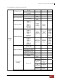
1.3 RAID Levels
The subsystem can implement several different levels of RAID technology. RAID levels
supported by the subsystem are shown below.
RAID Level Description
Min. Drives
0
Block striping is provide, which yields higher
performance than with individual drives. There
is no redundancy.
1
1
Drives are paired and mirrored. All data is 100%
duplicated on an equivalent drive. Fully
redundant.
2
N-way
mirror
Extension to RAID 1 level. It has N copies of the
disk.
N
3
Data is striped across several physical drives.
Parity protection is used for data redundancy.
3
5
Data is striped across several physical drives.
Parity protection is used for data redundancy.
3
6
Data is striped across several physical drives.
Parity protection is used for data redundancy.
Requires N+2 drives to implement because of
two-dimensional parity scheme
4
0 + 1
Mirroring of the two RAID 0 disk arrays. This
level provides striping and redundancy through
mirroring.
4
10
Striping over the two RAID 1 disk arrays. This
level provides mirroring and redundancy
through striping.
4
30
Combination of RAID levels 0 and 3. This level is
best implemented on two RAID 3 disk arrays
with data striped across both disk arrays.
6
50
RAID 50 provides the features of both RAID 0
and RAID 5. RAID 50 includes both parity and
disk striping across multiple drives. RAID 50 is
best implemented on two RAID 5 disk arrays
with data striped across both disk arrays.
6
60
RAID 60 provides the features of both RAID 0
and RAID 6. RAID 60 includes both parity and
disk striping across multiple drives. RAID 60 is
best implemented on two RAID 6 disk arrays
with data striped across both disk arrays.
8
JBOD
The abbreviation of “Just a Bunch Of Disks”.
JBOD needs at least one hard drive.
1

iSCSI GbE to SAS/SATA II RAID Subsystem
16
User Manual
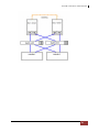
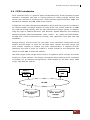
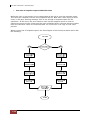
1.4 Volume Relationship Diagram
This is the design of volume structure of the iSCSI RAID subsystem. It describes the
relationship of RAID components. One RG (RAID Group) is composed of several PDs
(Physical Disks). One RG owns one RAID level attribute. Each RG can be divided into
several VDs (Virtual Disks). The VDs in one RG share the same RAID level, but may have
different volume capacity. Each VD will be associated with the Global Cache Volume to
execute the data transaction. LUN (Logical Unit Number) is a unique identifier, in which
users can access through SCSI commands.

iSCSI GbE to SAS/SATA II RAID Subsystem
User Manual
17
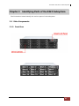
Chapter 2 Identifying Parts of the RAID Subsystem
The illustrations below identify the various parts of the subsystem.
2.1 Main Components
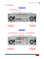
2.1.2 Front View

iSCSI GbE to SAS/SATA II RAID Subsystem
18
User Manual
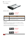
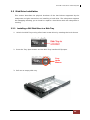
2.1.2.1 Disk Trays
HDD Status Indicator
Part
Function
HDD Activity LED
This LED will blink blue when the hard drive is being accessed.
HDD Fault LED
Green LED indicates power is on and hard drive status is good
for this slot. If hard drive is defective or failed, the LED is Red.
LED is off when there is no hard drive.
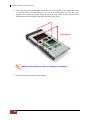
Lock Indicator
Every Disk Tray is lockable and is fitted with a lock indicator to indicate
whether or not the tray is locked into the chassis or not. Each tray is also fitted with
an ergonomic handle for easy tray removal.
When the Lock Groove is horizontal, this indicates that the Disk Tray is locked. When
the Lock Groove is vertical, then the Disk Tray is unlocked.

iSCSI GbE to SAS/SATA II RAID Subsystem
User Manual
19
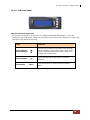
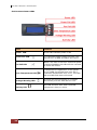
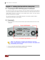
2.1.2.2 LCD Front Panel
Smart Function Front Panel
The smart LCD panel is an option to configure the RAID subsystem. If you are
configuring the subsystem using the LCD panel, press the Select button to login and
configure the RAID subsystem.
Parts Function
Up and Down
Arrow buttons
Use the Up or Down arrow keys to go through
the information on the LCD screen. This is also
used to move between each menu when you
configure the subsystem.
Select button
This is used to enter the option you have
selected.
Exit button EXIT
Press this button to return to the previous
menu.

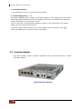
iSCSI GbE to SAS/SATA II RAID Subsystem
20
User Manual
Environment Status LEDs
Parts Function
Power LED Green LED indicates power is ON.
Power Fail LED
If a redundant power supply unit fails, this
LED will turn to RED and alarm will sound.
Fan Fail LED
When a fan fails or the fan’s rotational speed
is below 1500RPM, this LED will turn red and
an alarm will sound.
Over Temperature LED
If temperature irregularities in the system
occurs (HDD slot temperature over 65°C,
Controller temperature over 70°C), this LED
will turn RED and alarm will sound.
Voltage Warning LED
An alarm will sound warning of a voltage
abnormality and this LED will turn red.
Activity LED
This LED will blink blue when the RAID
subsystem is busy or active.
Page is loading ...
Page is loading ...
Page is loading ...
Page is loading ...
Page is loading ...
Page is loading ...
Page is loading ...
Page is loading ...
Page is loading ...
Page is loading ...
Page is loading ...
Page is loading ...
Page is loading ...
Page is loading ...
Page is loading ...
Page is loading ...
Page is loading ...
Page is loading ...
Page is loading ...
Page is loading ...
Page is loading ...
Page is loading ...
Page is loading ...
Page is loading ...
Page is loading ...
Page is loading ...
Page is loading ...
Page is loading ...
Page is loading ...
Page is loading ...
Page is loading ...
Page is loading ...
Page is loading ...
Page is loading ...
Page is loading ...
Page is loading ...
Page is loading ...
Page is loading ...
Page is loading ...
Page is loading ...
Page is loading ...
Page is loading ...
Page is loading ...
Page is loading ...
Page is loading ...
Page is loading ...
Page is loading ...
Page is loading ...
Page is loading ...
Page is loading ...
Page is loading ...
Page is loading ...
Page is loading ...
Page is loading ...
Page is loading ...
Page is loading ...
Page is loading ...
Page is loading ...
Page is loading ...
Page is loading ...
Page is loading ...
Page is loading ...
Page is loading ...
Page is loading ...
Page is loading ...
Page is loading ...
Page is loading ...
Page is loading ...
Page is loading ...
Page is loading ...
Page is loading ...
Page is loading ...
Page is loading ...
Page is loading ...
Page is loading ...
Page is loading ...
Page is loading ...
Page is loading ...
Page is loading ...
Page is loading ...
Page is loading ...
Page is loading ...
Page is loading ...
Page is loading ...
Page is loading ...
Page is loading ...
Page is loading ...
Page is loading ...
Page is loading ...
Page is loading ...
Page is loading ...
Page is loading ...
Page is loading ...
Page is loading ...
Page is loading ...
Page is loading ...
Page is loading ...
Page is loading ...
Page is loading ...
Page is loading ...
Page is loading ...
Page is loading ...
Page is loading ...
Page is loading ...
Page is loading ...
Page is loading ...
Page is loading ...
Page is loading ...
Page is loading ...
Page is loading ...
Page is loading ...
Page is loading ...
Page is loading ...
Page is loading ...
Page is loading ...
Page is loading ...
Page is loading ...
Page is loading ...
Page is loading ...
Page is loading ...
Page is loading ...
Page is loading ...
Page is loading ...
Page is loading ...
Page is loading ...
Page is loading ...
Page is loading ...
Page is loading ...
Page is loading ...
Page is loading ...
Page is loading ...
Page is loading ...
Page is loading ...
Page is loading ...
Page is loading ...
Page is loading ...
Page is loading ...
Page is loading ...
Page is loading ...
Page is loading ...
Page is loading ...
Page is loading ...
-
 1
1
-
 2
2
-
 3
3
-
 4
4
-
 5
5
-
 6
6
-
 7
7
-
 8
8
-
 9
9
-
 10
10
-
 11
11
-
 12
12
-
 13
13
-
 14
14
-
 15
15
-
 16
16
-
 17
17
-
 18
18
-
 19
19
-
 20
20
-
 21
21
-
 22
22
-
 23
23
-
 24
24
-
 25
25
-
 26
26
-
 27
27
-
 28
28
-
 29
29
-
 30
30
-
 31
31
-
 32
32
-
 33
33
-
 34
34
-
 35
35
-
 36
36
-
 37
37
-
 38
38
-
 39
39
-
 40
40
-
 41
41
-
 42
42
-
 43
43
-
 44
44
-
 45
45
-
 46
46
-
 47
47
-
 48
48
-
 49
49
-
 50
50
-
 51
51
-
 52
52
-
 53
53
-
 54
54
-
 55
55
-
 56
56
-
 57
57
-
 58
58
-
 59
59
-
 60
60
-
 61
61
-
 62
62
-
 63
63
-
 64
64
-
 65
65
-
 66
66
-
 67
67
-
 68
68
-
 69
69
-
 70
70
-
 71
71
-
 72
72
-
 73
73
-
 74
74
-
 75
75
-
 76
76
-
 77
77
-
 78
78
-
 79
79
-
 80
80
-
 81
81
-
 82
82
-
 83
83
-
 84
84
-
 85
85
-
 86
86
-
 87
87
-
 88
88
-
 89
89
-
 90
90
-
 91
91
-
 92
92
-
 93
93
-
 94
94
-
 95
95
-
 96
96
-
 97
97
-
 98
98
-
 99
99
-
 100
100
-
 101
101
-
 102
102
-
 103
103
-
 104
104
-
 105
105
-
 106
106
-
 107
107
-
 108
108
-
 109
109
-
 110
110
-
 111
111
-
 112
112
-
 113
113
-
 114
114
-
 115
115
-
 116
116
-
 117
117
-
 118
118
-
 119
119
-
 120
120
-
 121
121
-
 122
122
-
 123
123
-
 124
124
-
 125
125
-
 126
126
-
 127
127
-
 128
128
-
 129
129
-
 130
130
-
 131
131
-
 132
132
-
 133
133
-
 134
134
-
 135
135
-
 136
136
-
 137
137
-
 138
138
-
 139
139
-
 140
140
-
 141
141
-
 142
142
-
 143
143
-
 144
144
-
 145
145
-
 146
146
-
 147
147
-
 148
148
-
 149
149
-
 150
150
-
 151
151
-
 152
152
-
 153
153
-
 154
154
-
 155
155
-
 156
156
-
 157
157
-
 158
158
-
 159
159
-
 160
160
-
 161
161
-
 162
162


Proware EP-3164S1/D1-G1S3 User manual
- Category
- Server barebones
- Type
- User manual
- This manual is also suitable for
Ask a question and I''ll find the answer in the document
Finding information in a document is now easier with AI
Related papers
-
Proware EP-3164S1/D1-GAS3 Owner's manual
-
-
-
-
-
-
-
-
-
Other documents
-
Qsan Technology P300Q-S316 Datasheet
-
Rocstor Enteroc iS1030 User manual
-
MicroNet Genesis V User guide
-
-
APC SCSI-SATA II User manual
-
Tyco American Dynamics Expansion RAID Storage User manual
-
ACTi PSTR-0201 User manual
-
iStarUSA iAge820-ISCSI User manual
-
i3 International iS216 Quick start guide
-
Sans Digital accuraid ari08x Quick Installation Manual