Page is loading ...

1
HARMONYS Flash - outdoor
Installation and user manual
Notice d’installation et d’utilisation
Ensure upon reception that the product has not been damaged during transport.
S’assurer à réception que le produit n’a pas été endommagé durant le transport pour réserve au transporteur.
BODET SA
BP30 001
49340 TREMENTINES - France
Tel. support France: 02.41.71.72.99
Fax France: 02.41.71.72.01
Réf : 608128 B
www.bodet-time.com

2
EN
TABLE OF CONTENTS
1. GENERAL POINTS 4
1.1 Unpacking the Harmonys 4
1.2 Cleaning 4
1.3 Pré-requisit 4
1.4 Safety instructions - Precautions for use 4
2. INSTALLATION 5
3. USE - WEB SERVER 7
3.1 Home 7
3.2Networkconguration 8
3.3 Settings 9
3.4Alarmconguration 10
3.5 System 12
4. TECHNICAL SPECIFICATIONS 13
5. SUPPORT 14

3
FR
TABLE DES MATIERES
1. GÉNÉRALITÉS 15
1.1 Contenu de l’emballage 15
1.2 Nettoyage 15
1.3 Pré-requis 15
1.4 Consignes de sécurité - précaution d’utilisation 15
2. INSTALLATION 16
3. UTILISATION-SERVEURWEB 18
3.1Accueil 18
3.2Congurationréseau 19
3.3Paramètres 20
3.4Congurationdesalarmes 21
3.5 Système 23
4. CARACTERISTIQUES TECHNIQUES 24
5. ASSISTANCE 25

4
1. GENERAL POINTS
Thank you for choosing the Bodet HARMONYS Flash. This product has been carefully designed to meet your needs
in accordance with ISO9001 quality standards.
We recommend that you read this manual carefully before using the product for the first time.
Retain this manual throughout the lifespan of your product so that you can refer to it when necessary.
Failure to follow these instructions may cause irreversible damage and invalidate the warranty.
Non-contractual data. BODET reserves the right to make certain changes to its devices, regarding functional,
technical, aesthetic or colour characteristics, without prior notice.
This manual is subject to change without notice. To obtain the most recent version of this document, please refer to
our website: www.bodet-time.com.
1.1 Unpacking the Harmonys
For 907797, it must contain :
•Harmonys Flash for outdoor environment,
•The quick start guide.
1.2 Cleaning
Use an antistatic product.
Never use alcohol, acetone or other solvents which may damage product casing.
1.3 Pré-requisit
For the commissioning of the Harmonys sounder, you must install the SIGMA software (supplied on CD with your
master clock) on your PC. To download the latest version of the software, contact our export department who will
send you the download links by email: [email protected].
To check compatibility of your equipment and the software version, please have the version of your
master clock.
1.4 Safety instructions - Precautions for use
Thisequipmentmustbettedandmaintainedbyaqualiedperson.
The Outdoors Harmonys Flash connects to the mains power supply. The installation must comply with standard
IEC 364 (NFC 15-100 in France).
The product must be powered by the building’s electrical system. It is designed for category II overvoltages. Clipping
max: 2500 V (provide protection on the power supply if necessary).
Cables must be tightened at the glands to ensure that no stress is placed on the connection terminals. Furthermore,
conductors on the same circuit must be attached to each other close to the terminal block to avoid reduced isolation
should one of the terminals become loose.
Provide a Phase-neutral circuit breaker of 16 A maximum, rapidly accessible upstream from the power-supply line.
This circuit breaker provides power supply protection and disconnecting, and must be cut off in the event of main-
tenance.
The equipment must only be powered up after it has been attached.
ENEN

5
EN
1
2
3
4
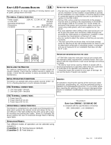
2. INSTALLATION
1- Determine the location where the Harmonys Flash rotating beacon will be installed according to the location of the
control box: a 5-meter cable is provided to ensure the link between the 2 elements.
2- Determine the placement of the Harmonys Flash control box, ensuring that the power supply (mains socket) and
Ethernet cable are within reach.
3- Open the box by unscrewing the 4 screws
1
withaat-tipscrewdriver.Removethe
cover from the box.
4- Attach the control box in position using 3 screws
2
. Refer to the dimensions below.
Note: The 4th screw can be used
3
to attach the control box. Unscrew the
3 nuts on the electronic board
4
toaccessthenalcontrolboxscrew
3
.
5- Pass the network cable and the rotating beacon cable through the largest of the two
cableglands.Themainspowersupplycableshouldtalonethroughthesmallest
cable gland.
6-Installtherotatingbeaconinitsnalposition.Ensurethatitiscorrectlyattachedtothe
cable clips and also to its support (e.g. the wall) to avoid vibrations.
7- Mount the information sign as close as possible to the beacon.
Dimensions for mounting
View of the inside of the control box
The equipment must not be powered on until the mounting is completed.
37
310
250
184
184
195
250
97,5
194
140
PG7
PG16

6
8- Connect the power cord (not supplied) :
- Unscrew the 4 screws from the plate a few millimeters where the power supply
and electronic board are installed.
- Remove the power supply block from the box by shifting then pulling towards yourself:
the teardrop-style holes will make it possible to extract the power supply without
completely loosening the screws.
- Remove the transparent plastic protective sleeve.
- Attach power supply cable to power supply unit respecting polarity:
L, N, E (Live, Neutral, Earth)
Attach the three cables together the using the plastic collar provided.
9- Connect the rotating beacon’s connection cable (2 wires) with the control box to the green
connector of the electronic board in OUT mode. Respect polarity: V- (earth), V+ (+24V).
25 mm unsheathed cable.
7 mm stripped wires.
Attach the two cables together the using the plastic collar provided.
10- Put the transparent plastic protective sleeve back in place and reposition
the power supply unit.
11- Close the control box.
All cables should be tightly wired inside the control box (no traction).
We advise against inserting excess cable length inside the control box.
Harmonys flash powered up (box open):
« Test » Button: press once to test the operation of the flashing beacon (start
and stop of the test mode).
- The « ~ » LED (green) indicates the presence of power.
-The«Ψ»LED(green/red)indicatesthenetworkstatus.
> Green = Network synchronisation OK
> Red = Network synchronization error
After the product have been powered up, it waits for a command from the mas-
ter clock.
EN

7
3. USE - WEB SERVER
There are two methods of accessing the web interface:
1) Open a page in your internet browser then, in the search bar, enter the IP address of the product present on your
network (for example, 192.0.1.128).
2) Use the Sigma software, in the menu Configuration > IP devices > Harmonys Flash tab click on the button Web
server access to open the web server (refer to software manual, 607726).
The SIGMA software can be used to:
- detect the devices present on the network,
- configure each device (independently of each other, or copy the settings of one device to a group of devices),
- update the device’s software version,
3.1 Home
The home page contains the following general information:
- Product: product type.
- Name: product name + MAC address (in correspondence with the MAC address noted on the product identification
label during installation). By default: “Bodet-MAC address” (modifiable in the Network configuration
menu). The default value can be used to locate the product on the network on commissioning.

8
EN
3.2 Networkconguration
This page can be used to configure the device on the network as follows:
- MAC address: this is the MAC address of the device. This address is unique to each product. This number is
indicated on a label on the rear of Bodet devices.
- Name: product name + MAC address (by default). It is advisable to include the physical location of the device in the
name of the product. Example: Flash_Home
- Enable DHCP tick box: enables automatic definition of the IP settings of the product on the network (where a DHCP
server is present on the network).
When the Enable DHCP tick box is not checked, the following parameters can be set manually:
- IP Address: allows manual definition of the product’s IP address.
- Mask: the subnet mask can be used to associate a device with the local network.
- Gateway: the gateway can be used to connect the device to two computer networks.
- DNS address: address which can be used to associate a product name with an IP address. This eliminates the need
to enter an IP address into the browser, as it can be replaced with a number or name defined by the
user, Example: www.bodet.com being easier to remember than 172.17.10.88.
The Save and Reboot button can be used to save data changes in the concerned device, and then restart it.

9
EN
3.3 Settings
This page can be used to configure the operational settings of the device as follows:
- Multicast (Address A and B): multicast address for sending ring commands (no schedule sent) (by default:
A=239.192.55.1, B= not specified).
- Brightness: adjustment of Brightness has no effect on this model.
- N° Zone: enables definition of the number of the zone in which the product is located.
- Client repeater/server (tick box): in the case of a complex network installation with one or more remote sites, it may
be necessary to set up network gateways. To do so, it will be necessary to define
repeaters which will pass the information from one network to the other. For
each pair, one sounder is defined as the server and the other as the client. It is
advisable, although not compulsory, to place the server repeaters in the network
where the Sigma is located (and the microphone).
- Repeater address: can be used to enter the network address of the other sounder in the repeater pair.
The buttons Save and Save and Reboot can be used to save data changes in the concerned device, and then restart it.
3.4 Alarmconguration

10
EN
This page is used to enable device supervision, to define the information to be transmitted and the destination server.
One or more settings can be defined and configured as alarms.
The following information is displayed:
• SNMP - SNMP Trap: If enabled, error messages are sent to the SNMP Manager(s) automatically.
• Version: choice of SNMP protocol version
• Tick SNMP Trap box: activates (or not) the automatic sending of error messages to SNMP managers.
• SNMP Manager 1/2/3: IP addresses of servers receiving alerts from the clocks. SNMP Manager redundancy
increases the reliability of alerts.
• Community:Asetofclocksdenedbytheuser.Alltheclocksonthenetworkmusthavethesame
Community name.
• Reboot: This setting is used to detect a clock reboot.
• Scheduled melody: This parameter triggers an alarm when a programmed melody is played.
• Manual melody: This parameter is used to trigger an alarm when melody is initiated manually.
• Alert melody: This parameter triggers an alarm when an alert melody is played.
• Web access: This setting is used to trigger an alert if a user connects to the web server of the clock.
• Authentication failure: This setting is used to trigger an alert if a user sends an incorrect ID to the web server
of the clock.
• Repeater failure: This parameter triggers an alarm when a fault occurs on the repeater.
• Periodic Status: This setting is used to verify that the device is still working correctly (in case alerts are
“lost”).Thisvericationiscarriedoutatasetfrequency.

11
EN
Information: Information on the normal operation of the product or the errors or faults reported are
minor and a visit by a maintenance technician to correct the fault is not strictly
necessary.
Warning: The errors or faults reported are significant and a visit by a maintenance technician to correct
the fault is necessary.
Critical: The errors or faults reported are serious and an urgent visit by a maintenance technician to
correct the fault is necessary.
Save is used to save any settings made on this page.
Send status trap is used to send a trap status to all of the configured SNMP managers to ensure that supervision is
configured correctly (make sure you click OK to save the settings).

12
EN
3.5 System
This page is divided into four parts as follows:
Part 1: presentation of the version of the program (firmware) and the operating duration since the device was last
switched on.
Part 2: a warning message indicates that once defined, it is compulsory to use the correct password to establish a
connection with the web server. To save a username and password (max 16 characters), enter the information
in the spaces provided for this purpose. The Save button can be used to save your new username and
password.
Part 3: the warning message indicates that restarting the device will cause a loss of connection to the network during
the restart. The Reboot button restarts the product.
Part 4: the warning message indicates that restoring factory settings will delete all your settings and may lead to
the device losing connection to the network, in the absence of a DHCP server on the network. The Factory
config + Reboot button restarts the product to factory settings.

13
EN
4. TECHNICAL SPECIFICATIONS
•Construction............................................
Housing:polycarbonatereinforcedwithglassber.
Beacon: Orange shockproof polycarbonate lens and black polyamide base.
•Mounting..................................................
Wall mounting bracket.
•Protection Index...................................... IP 54, IK 07.
•Dimensions.............................................. Control box: L250 x W195 x D97,5 mm.
The information sign: L200 x W200 x H4 mm thick.
The beacon: - Diameter: 105 mm.
- Lamp: H1 (70W).
- Weight: 690 gr.
•Cables entry method............................... PG16 cable gland for power cable.
PG7 cable gland for beacon and Ethernet cables.
•Operating temperature range................. -20 to +50°C.
•Power supply............................................ 110-230 VAC.
•Consumption........................................... 110-230 VAC ; 1,25-0,68 A.
•Electrical insulation................................. Class I.
•Power supply connections..................... 3 terminals - N (neutral) and L (phase) for 0.5 to 2.5mm².
• Distance between the controller and
the beacon................................................ 5 meters (the cable is supplied).

14
EN
•Construction.........................................
Orange shockproof polycarbonate lens and black polyamide base.
•Mounting...............................................
Wall mounting bracket.
•ProtectionIndex.................................... IP 54, IK 07.
•Dimensions........................................... Control box: L250 x W195 x D97,5 mm.
The information sign: 200 x 200, 4 mm thick.
The beacon: - Diameter: 105 mm.
- Weight: 690 gr.
- Lamp: H1 (70 W).
•Dimensionsenteredbycables............... PG11 cable gland for power cable.
PG7 cable gland for beacon and Ethernet cables.
•Operatingtemperaturerange................ -20 to +50°C.
•Powersupply......................................... 100 to 240VAC (± 10%) - 50/60Hz.
•Consumption......................................... 0,5A at 230VAC.
•Electricalinsulation.............................. Class I.
•Powersupplyconnections.................... 2 terminals - N (neutral) and L (phase) for 2.5mm² max. wires.
•Distancebetweenthecontrollerand
thebeacon............................................ 5 meters (the cable is supplied).
5. SUPPORT
What to do if…? ... Check
Nobroadcastingash
1) The multicast address is identical between the master clock and Harmonys.
2) Network parameters are compatible: Harmonys must be on the same Ethernet
network as the computer with the Sigma software.
No DHCP server on the
network
1) By default the Harmonys takes on the following IP setting (after 3min):
- IP: 192.192.223.100 (1st sounder), 192.192.222.101 (2nd sounder), etc.
- MASK: 255.255.0.0
- Gateway: 0.0.0.0
- DNS: 0.0.0.0
(After 15 minutes, the sounder asks an address DHCP server).
2)UsingtheSigmasoftware(Conguration>IPdevices>Networkbutton)tosetthe
networksettingsHarmonys(productidenticationwiththeMACaddressonthetag
on the back of the product).
Harmonys does not
broadcastanysash
1) The length of the cable is lower than 100 meters (refer to the standards of network
cabling).
2) Harmonys sounder is on the broadcast area of the master clock Sigma.
3) The multicast address is identical between the master clock and Harmonys.
4)Theversionrmwareoftheswitchisuptodate.

15
1. GÉNÉRALITÉS
Nous vous remercions d’avoir choisi l’Harmonys Flash d’extérieur BODET. Ce produit a été conçu avec soin pour
votre satisfaction d’après les bases qualité ISO9001.
Nous vous recommandons de lire attentivement cette notice avant de commencer à manipuler le produit.
Conserver cette notice pendant toute la durée de vie de votre produit afin de pouvoir vous y reporter à chaque fois
que cela sera nécessaire.
Tout usage non conforme à la présente notice peut causer des dommages irréversibles, et entraîner l’annulation de
la garantie.
Données non contractuelles. La société BODET se réserve le droit d’apporter aux appareils certaines modifications
fonctionnelles, techniques, esthétiques, ou de couleurs, sans préavis.
Ce manuel est sujet à des changements sans préavis. Pour obtenir la version la plus récente de cette documentation,
consulter notre site internet : www.bodet-time.com.
1.1 Contenu de l’emballage
Déballersoigneusementleproduitetvérierlecontenudel’emballage.
La référence 907797 doit comprendre :
■unHarmonysFlashpourextérieur,
■unguidededémarragerapide.
1.2 Nettoyage
Utiliser un produit antistatique.
Ne pas utiliser d’alcool, d’acétone ou autres solvants susceptibles d’endommager le produit.
1.3 Pré-requis
Pour la mise en service de ces produits, installer le logiciel SIGMA (fourni sur CD-Rom avec votre horloge mère).
Pour obtenir la dernière version du logiciel, contactez notre assistance clientèle qui vous transmettra les liens de
téléchargement, par e-mail à l’adresse : [email protected].
andevérierlacompatibilitédeséquipementsetlaversiondulogicielàinstalleravecnotre
assistance clientèle, se munir de la version logicielle de l’horloge mère.
1.4 Consignes de sécurité - précaution d’utilisation
l’installation et l’entretient de ce matériel doivent être réalisés par une personne habilitée.
L’Harmonys Flash extérieur est raccordé à l’alimentation secteur. L’installation doit être conforme à la norme IEC
364 (NFC 15-100 pour la France).
Le produit doit être alimenté par l’installation électrique du bâtiment. Il est conçu pour des surtensions de catégorie
II. Écrête maxi : 2500V (prévoir une protection sur l’alimentation si nécessaire).
Lesdifférentscâblesdoiventêtreserrésdanslespresse-étoupesande ne pas exercer decontraintessurles
bornes de raccordement. De plus, les conducteurs d’un même circuit doivent être attachés entre eux près du bornier
pour éviter une réduction de l’isolation dans le cas où une des bornes viendrait à se desserrer.
Prévoir un disjoncteur phase-neutre de 16 A maximum, rapidement accessible en amont de la ligne d’alimentation.
Ce disjoncteur assure la protection et le sectionnement de l’alimentation et doit être coupé en cas de maintenance.
lematérieldoitêtremissoustensionqu’aprèssaxation.
FR

16
2. INSTALLATION
1-Dénirl’emplacementdugyrophareens’assurantdelaproximitéduboîtierdecommande:uncordonde5mètres
est livré pour la liaison entre les deux éléments.
2-Dénirl’emplacementduboîtierdecommandedel’HarmonysFlashens’assurantdelaproximitédel’alimentation
(prise secteur) et du câble réseau Ethernet.
3- Ouvrir le boîtier en dévissant les 4 vis
1
à l’aide d’un tournevis plat. Ôter le
couvercle du boîtier.
4-Fixerleboîtierdecommandeàsonemplacementàl’aidede3visdexation
2
. Se
reporter aux dimensions ci-dessous.
Note:ilestpossibled’utiliserla4èmevisdexation
3
pourxerleboîtierde
commande. Dévisser les 3 écrous
4
puis retirer la carte électronique
pouraccéderàladernièrevisdexationduboîtierdecommande
3
.
5- Passer le câble réseau ainsi que le câble du gyrophare dans le plus gros des deux
presse-étoupes. Le câble d’alimentation secteur doit passer seul dans le plus petit
presse-étoupe.
6-Installerlegyrophareàl’emplacementdéni.Veilleràcequ’ilsoitbienplaquésurlaxationtubeàvisseretaussi
sur le support (ex : mur) pour éviter les vibrations.
7- Fixer le panneau d’information au plus près du gyrophare.
Cotes pour xation
Vue intérieure du boîtier d’alimentation
lematérielnedoitêtremissoustensionqu’aprèsxation.
37
310
250
184
184
195
250
97,5
194
140
FR
1
2
3
4
PG7
PG16

17
8- Brancher le câble d’alimentation (non fourni) :
-Dévisserles4visdexationdelaplatinedequelquesmillimètressurlaquelleest
implantée l’alimentation.
- Sortir le bloc alimentation du boîtier en décalant puis en tirant vers soi : les gouttes
d’eau permettront d’extraire l’alimentation sans dévisser totalement les vis.
- Ôter la barrette de protection en plastique transparent.
- Connecter le câble d’alimentation au bloc alimentation en respectant la
polarité : L, N, T (phase, neutre, terre).
Attacherlestroislsentreeuxàl’aideducollierplastiquefourni.
9-Brancherlecâble(2ls)deliaisondugyrophareavecleboîtierdecommandesurleconnecteur
vert de la carte électronique en OUT. Respecter la polarité : V- (masse), V+ (+24V).
Câble dégainé de 25 mm.
Fils dénudés de 7 mm.
Attacherlesdeuxlsentreeuxàl’aideducollierplastiquefourni.
10- Remettre la barrette de protection en plastique transparent puis replacer le bloc
alimentation.
11- Refermer le boîtier de commande.
touslescâblesdoiventêtrecabléstendusàl’intérieurduboîtierdecommande(sanstraction).Ilest
déconseilléd’insérerl’excédentdescâblesàl’intérieurduboîtierdecommande.
HarmonysFlashsoustension(boîtierouvert):
Bouton «Test» : un appui permet de tester le fonctionnement du gyrophare
(lancement et arrêt du mode test).
- La LED «~» (verte) indique la présence de l’alimentation.
-LaLED«Ψ»(verte/rouge)signalelacongurationdusystème.
> Verte = synchronisation réseau OK
> Rouge = erreur de synchronisation réseau
Après la mise sous tension du produit, celui-ci attend un ordre d’exécution
venant de l’horloge mère.
FR

18
3. UTILISATION - SERVEUR WEB
Pour accéder à l’interface web, il existe deux solutions :
1) Ouvrir une page du navigateur internet puis dans la barre de recherche, entrer l’adresse IP du produit présent sur
le réseau (Par exemple : 192.0.1.128).
2) Utiliser le logiciel Sigma, dans le menu Configuration > équipements IP > Onglet Harmonys Flash, cliquer sur
le bouton Accès serveur web pour ouvrir le serveur web (se reporter à la notice du logiciel, 607726).
Le logiciel SIGMA permet de :
- détecter les équipements présents sur le réseau,
- paramétrer chaque équipement (indépendamment les uns des autres ou copier les paramètres d’un
équipements vers un groupe d’équipements),
- mettre à jour la version logicielle de l’équipement,
3.1 Accueil
La page d’accueil synthétise les informations générales suivantes :
- Produit : type de produit.
- Nom : BODET + @MAC. @MAC est l’adresse MAC du produit, elle varie d’un produit à l’autre et est en
correspondance avec l’adresse MAC relevé sur l’étiquette d’identification du produit lors de son installation.
L’adresse MAC est modifiable dans le menu Configuration réseau. Cette valeur par défaut permet de
retrouver le produit sur le réseau à la mise en service.
FR

19
3.2 Congurationréseau
Cette page permet de configurer l’équipement sur le réseau de la façon suivante :
- Adresse MAC : il s’agit de l’adresse MAC de l’équipement. Cette adresse est unique pour chaque produit. Ce
numéro est indiqué sur une étiquette au dos des équipements Bodet.
- Nom : nom du produit + adresse MAC (par défaut). Il est conseillé de mettre l’emplacement de l’équipement dans le
nom du produit. Exemple : Flash_Accueil.
- Case à cocher DHCP : permet de définir automatiquement les paramètres IP du produit sur le réseau (dans le cas
où un serveur DHCP est présent sur le réseau).
Si celle-ci est décochée, les paramètres suivants sont modifiables :
- Adresse IP : permet de définir manuellement l’adresse IP du produit.
- Masque : le masque de sous réseau permet d’associer un équipement au réseau local.
- Passerelle : la passerelle permet de relier l’équipement à deux réseaux informatiques.
- Adresse DNS : adresse permettant d’associer un nom de produit à une adresse IP. Cela permet d’éviter de rentrer
une adresse IP dans le navigateur au profit d’un numéro ou appellation définie par l’utilisateur.
Exemple : www.bodet.com étant plus simple à retenir que 172.17.10.88.
Le bouton OK et Redémarrage permet de sauvegarder les données modifiées dans l’équipement concerné, puis de
le redémarrer.
FR

20
3.3 Paramètres
Cette page permet de configurer les paramètres fonctionnels de l’équipement de la façon suivante :
- Adresses Multicast (adresse A et B) : adresses multicast pour l’envoi des commandes de flashage (par défaut :
A=239.192.55.1, B=non renseignée).
- Luminosité : ajustement de la luminosité sans effet sur ce modèle.
- N° de zone : permet de définir le numéro de la zone dans laquelle se trouve le produit.
- Répéteurclient/serveur(caseàcocher): dans le cas d’installation réseau complexe avec un ou plusieurs sites
distants, il peut être nécessaire de devoir passer des passerelles réseau.
Pour cela, il faut définir des répéteurs qui feront passer les informations
d’un réseau à l’autre. Sur chaque paire, un carillon est défini comme
serveur et l’autre comme client. Il est recommandé mais pas obligatoire
de placer les répéteurs serveur dans le réseau où se trouve la Sigma
(et le microphone).
- Adresse répéteur : permet de renseigner l’adresse réseau de l’autre carillon de la paire de répéteur.
Les boutons OK et OK et redémarrage permettent de sauvegarder les données modifiées dans l’équipement
concerné, puis de le redémarrer.
FR
/