Page is loading ...

1
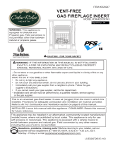
LIQUID PROPANE
CONVERSION SAFETY
PILOT KIT
Model #SPK100
FOR USE WITH MODELS
VL-WO18D
VL-WO24D
VL-WO30D
VL-AA18D
VL-AA24D
VL-AA30D
VL-NO24D
VL-NO30D
- Do not store or use gasoline or other ammable vapors and liquids in the vicinity of this or
any other appliance.
- WHAT TO DO IF YOU SMELL GAS
• Do not try to light any appliance.
• Do not touch any electrical switch; do not use any phone in your building.
• Immediately call your gas supplier from a neighbor’s phone. Follow the
gas supplier’s instructions.
• If you cannot reach your gas supplier, call the re department.
- Installation and service must be performed by a qualied installer, service agency or
the gas supplier.
0418GL012S
ANSI Z21.60-2012
IMSPK - 2018-04-04
WARNING: IF THE INFORMATION IN THIS MANUAL IS NOT FOLLOWED
EXACTLY, A FIRE OR EXPLOSION MAY RESULT CAUSING PROPERTY
DAMAGE, PERSONAL INJURY OR LOSS OF LIFE.
CAUTION - FOR YOUR SAFETY
INSTALLER: Leave this manual with the appliance.
CONSUMER: Retain this manual for future reference.
WARNING:
This conversion kit shall be
installed by a qualied service
agency in accordance with the
manufacturer's instructions
and all applicable codes and
requirements of the authority
having jurisdiction. The infor-
mation in these instructions
must be followed to minimize
the risk of re or explosion
or to prevent property dam-
age, person injury or death.
The qualied service agency
performing this work assumes
responsibility for the proper
conversion of this appliance
with the kit.
Questions, problems, missing parts? Before returning to your retailer, call our customer
service department at 1-877-447-4768, 8:30 a.m. – 4:30 p.m., CST, Monday – Friday or
email us at [email protected].


2
TABLE OF CONTENTS
Specications ................................................................................................................................... 3
Important Safety Information ............................................................................................................4
Product Identication ........................................................................................................................5
Product Features ..............................................................................................................................6
Unpacking.........................................................................................................................................6
Preparing for Installation...................................................................................................................7
Installation ........................................................................................................................................ 8
Operation ........................................................................................................................................12
Troubleshooting ..............................................................................................................................16
Replacement Parts ......................................................................................................................... 17
Placement of Decals..................................................................................................................18-19
Uninstallation & Conversion Back to Natural Gas ..........................................................................20
Warranty .........................................................................................................................................21
Note: This vented appliance must be installed only in a solid-fuel burning replace with a working
ue and constructed of noncombustible material.
Solid fuels shall not be burned in a replace where a decorative appliance is installed.
The charts indicate technical information regarding the installation of your gas log set.
Please make sure that all of the specications shown are applicable before installation is attempted.
High Altitude Locations:
For high altitude installations in the United States, refer to the American Gas Association guidelines
for the gas designed appliance derating method. For elevations above 2,000 ft (610 m), input
ratings are to be reduced by 4% for each 1,000 ft (305 m) above sea level.
SPECIFICATIONS
Input Rating
Gas Type
Ignition Type
Max. Inlet Pressure
Min. Inlet Pressure
Manifold Pressure
VL-WO24D
VL-AA24D
VL-NO24D
45,000 BTU/hr
VL-WO30D
VL-AA30D
VL-NO30D
55,000 BTU/hr
VL-WO18D
VL-AA18D
35,000 BTU/hr
LP
Piezo Ignitor
14’’ WC
11’’ WC
10’’ WC
LP
Piezo Ignitor
14’’ WC
11’’ WC
10’’ WC
LP
Piezo Ignitor
14’’ WC
11’’ WC
10’’ WC
Model

3
SPECIFICATIONS
IMPORTANT: Read this owner’s manual carefully and completely before trying to assemble, operate,
or service this log set. Improper use of this log set can cause serious injury or death from burns, re,
explosion, electrical shock, and carbon monoxide poisoning.
Only a qualied installer, service agent, or local gas supplier may install and service this product.
WARNING: Do not store or use gasoline or other ammable vapors or liquids in the vicinity
of this or any other appliance.
WARNING: The log set is shipped from the factory adjusted for natural gas use only. Liquid
Propane can only be used after installation of Liquid Propane Conversion Safety Pilot Kit.
CARBON MONOXIDE POISONING: Early signs of carbon monoxide poisoning resemble the u
with headaches, dizziness, or nausea. If you have these signs, the log set may not be working properly.
Get fresh air immediately! Have log set serviced. Some people are more affected by carbon monoxide
than others. These include pregnant women, people with heart or lung disease, people who are
anemic, those under the inuence of alcohol, and those living in high altitudes.
NATURAL AND PROPANE/LP GAS: Natural and Propane/LP gases are odorless. An odor-making
agent is added to the gas. The odor helps you detect a gas leak. However, the odor added to the
gas can fade. Gas may be present even though no odor exists. Make certain you read and under-
stand all warnings. Keep this manual for reference. It is your guide to operating this log set safely.
WARNING:
- Due to high temperatures, locate this appliance out of trafc and away from furniture
and draperies.
- Log set becomes very hot when operating. Keep children and adults away from hot
surfaces to avoid burns or clothing ignition. Log set will remain hot for a time after shut-
off. Allow surfaces to cool before touching.
- Carefully supervise young children when they are in the room with the log set.
- Do not place clothing or other ammable material on or near the appliance. Never place
any objects in the log set.
- Installation and repair should be done by a qualied service person. The appliance
should be inspected before use and at least annually by a professional service person.
More frequent cleaning may be required due to excessive lint from carpeting, bedding
material, etc. It is imperative that control compartments, burners and circulating air pas-
sageways of the appliance be kept clean.
- Any change to this log set or its controls can be dangerous.
- Do not use any accessories not approved for use with this log set.
- Keep the appliance area clear and free from combustible materials, gasoline, and other
ammable vapors and liquids.
WARNING
This product and the fuels used to operate this product (liquid propane or natural gas), and the
products of combustion of such fuels, can expose you to chemicals including benzene, which is
known to the State of California to cause cancer and reproductive harm.
For more information go to www.p65Warnings.ca.gov

4
SAFETY INFORMATION
1. This appliance is only for use with the type of gas indicated on the rating plate. 2.
Do not place
propane/LP supply tank(s) inside any structure. Locate propane/LP supply tank(s) outdoors.
3. If you smell gas
• shut off gas supply
• do not try to light any appliance
• do not touch any electrical switch; do not use any phone in your building
• immediately call your gas supplier from a neighbor’s phone. Follow the gas supplier’s instructions
• if you cannot reach your gas supplier, call the re department
4. This log set shall not be installed in a bedroom or bathroom.
5. Do not use this log set as a wood-burning log set. Use only the logs provided with the log set.
6. Do not add extra logs or ornaments such as pine cones, vermiculite or rock wool. Using these
added items can cause sooting.
7. This log set is designed to be smokeless. If logs ever appear to smoke, turn off log set and call a
qualied service person. Note: During initial operation, slight smoking could occur due to log curing
and log set burning manufacturing residues.
8. To prevent the creation of soot, follow the instructions in Cleaning and Maintenance in your Vented
Log Set Owners Manual.
9. Before using furniture polish, wax, carpet cleaner or similar products, turn log set off. If heated,
the vapors from these products may create a white powder residue within burner box or on adjacent
walls or furniture.
10. This log set needs fresh air ventilation to run properly.
11. Do not run log set
• where ammable liquids or vapors are used or stored.
• under dusty conditions.
12. Do not use this log set to cook food or burn paper or other objects.
13. Never place any objects in the replace or on the logs.
14. Do not use log set if any part has been under water. Immediately call a qualied service technician to
inspect the log set and to replace any part of the control system and any gas control which has been
under water.
15. Turn off and unplug log set and let cool before servicing. Only a qualied service person should
service and repair log set.
16. To prevent performance problems, do not use propane/LP fuel tank of less than 100 lb. capacity.
17. Provide adequate clearances around air openings.
QUALIFIED INSTALLING AGENCY
Only a qualied agency should install and
replace gas piping, gas utilization equip-
ment or accessories, and repair and equip-
ment servicing. The term "qualied agency"
means any individual, rm, corporation, or
company that either in person or through a
representative is engaged in and is respon-
sible for:
a) Installing, testing, or replacing gas piping or
b)Connecting, installing, testing, repairing, or
servicing equipment; that is experienced in
such work; that is familiar with all precautions
required; and that has complied with all the re-
quirements of the authority having jurisdiction.

5
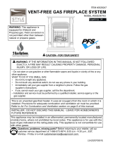
PRODUCT IDENTIFICATION
Piezo
Piezo Nut
Control
Knob
Control
Valve
Heat Shield
Control Valve
Nut
Nipple
Orifice
Air Nozzel
Flare
Fitting
Burner Pan
Assembly
Piezo Wire
Pilot Wire
Pilot Gas Line
Pilot Bracket
Pilot Assembly
Notice: Use caution not
to damage or break the
aluminum pilot wire when
routing and connecting.
Nipple Regulator

6
PRODUCT FEATURES
LIQUID PROPANE CONVERSION & SAFETY PILOT
This system requires no matches, batteries, or other sources to light. You must use this optional sys-
tem for Propane/LP conversion.
The State of Massachusetts requires that the chimney ue damper, when used with decorative
gas log sets, be welded open or completely removed. In the State of Massachusetts, this
appliance must be installed by a licensed plumber or gastter.
In the State of Massachusetts the gas cock must be a T-handle type. The State of
Massachusetts requires that a exible appliance connector cannot exceed three feet
in length.
LOCAL CODES
Install and use log set with care. Follow all codes. In the absence of local codes, use the
latest edition of The National Fuel Gas Code, ANSI Z223.1, also known as NFPA 54*.
*Available from:
American National Standard Institute, Inc. National Fire Protection Association, Inc.
1430 Broadway 1 Batterymarch Park
New York, NY 10018 Quincy, MA 02269-9101
UNPACKING
1. Remove logs, pan materials,
and hardware from carton.
2. Remove all protective packaging applied
to logs and base for shipment.
3. Check all items for any shipping damage.
If damaged, promptly inform dealer where
you bought the product.
CAUTION: Do not remove the
metal data plates from the burner
pan. The data plates contain
important product information.

7
This safety pilot system must be installed by a qualied profession service technician.
Before beginning assembly of product, make sure all parts are present. Compare parts with
package contents list. If any part is missing or damaged, do not attempt to assemble the
product. Contact customer service for replacement parts.
Estimated Assembly Time: 60 minutes
Tools Required for Assembly (not included): Philips Screwdriver, Pipe Sealant, Adjustable
Wrench Sediment Trap and Manual Shutoff Valve.
PREPARING FOR INSTALLATION

8
INSTALLATION
This safety pilot system must be installed by a qualied
profession service technician.
Note: Installation is easier when done outside of the
replace.
Save the orices removed from the appliance for future
use.
Liquid Propane Conversion Safety Pilot Kit
Assembly Instructions
1. Determine which side of the burner assembly the
control will be on – Left or Right and attach ON‐OFF
Label to Valve Bracket.
-This assembly illustration shows the control on the
right side.
2. Attach Piezo Ignitor to Valve Bracket.
3. Attach Valve to Valve Bracket.
4. Install Knob to Valve.
5. Attach Nozzle to Burner Pan.
Pilot Bracket
Nozzel
Pilot Assembly
Remove screws in Burner Pan
and use these to install
Pilot Bracket
Burner Pan
WARNING: Failure to position the
parts in accordance with these
diagrams or failure to use only parts
specically approved with this appli-
ance may result in property damage
or personal injury.
Install Knob

9
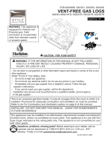
INSTALLATION
6. a. Attach Threaded Nipple to Valve.
b. Install proper Orice for the size Log
Set into Threaded Nipple.
c. Install Flare Fitting to inlet of Valve.
Note: Save the orices removed from the appliance
for future use.
7. Attach Orice to Nozzle by rotating the
complete Valve Bracket Assembly.
Tighten securely until Valve Bracket
Assembly is level with burner pan.
8. Attach Pilot Bracket and Pilot Assembly
to Burner Pan.
9. Notice: Use caution not to damage or break the
aluminum pilot wire when routing and connecting.
a. Connect Pilot Gas Line to Valve.
Finger tight quarter turn.
b. Connect Thermocouple Wire to Valve.
Finger tight, quarter turn.
c. Connect Piezo Wire to Piezo
DETAIL A
A
Select the correct orifice
for your burner size;
18 for an 18" Burner Size (#50)
24 for a 24" Burner Size (#46)
30 for a 30" Burner Size (#43)
Piezo Wire
Thermocouple Wire
Pilot Gas Line
Complete the assembly by
screwing the Pilot Gas Line
and Thermocouple Wire into
the Valve by turning clockwise.
Push the Piezo Wire into the
Piezo connection as illustrated.
Screw the Orifice into
the Nozzel by rotating
the entire valve bracket
assembly clockwise.
Tighten securely until
valve bracket assembly
is level with burner pan.
Orifice
Nozzel
Valve
Bracket
Assembly
Burner Pan
Install Knob
Burner Pan
Assembly

10
CONNECTION TO GAS SUPPLY
WARNING: A qualied service person must
connect log set to gas supply. Follow all local
codes.
Installation Items Needed
Before installing log set, make sure you have
the items listed below.
• piping (check local codes)
• sealant (resistant to natural gas)
• equipment shutoff valve
• test gauge connection
• adjustable (crescent) wrench or pliers
• sediment trap
• tee joint
• pipe wrench
CAUTION: Only use a new, black iron or steel
pipe. Internally-tinned copper tubing may
be used in certain areas. Check your local codes.
Use pipe of 1/2" diameter or greater to allow
proper gas volume to log set. If pipe is too small,
loss of pressure will occur.
Installation must include an equipment shutoff
valve, union, and plugged 1/8" NPT tap.
Locate NPT tap within reach for test gauge
hook up. NPT tap must be upstream from log
set (see Figure 1).
IMPORTANT: Install equipment shutoff valve
in an accessible location. The equipment
shutoff valve is for turning on or shutting off
the gas to the appliance.
Apply pipe joint sealant lightly to male threads.
This will prevent excess sealant from going
into pipe. Excess sealant in pipe could result
in a clogged burner injector.
Install sediment trap in supply line. Locate sedi-
ment trap where it is
within reach for cleaning. Locate sediment
trap where trapped matter is not likely to
freeze. A sediment trap traps moisture and
contaminants. This keeps them from going
into log set controls. If sediment trap is not
installed or is installed incorrectly, log set may
not run properly.
INSTALLATION
Fig. 1
Approved
Flexible
Gas Line
or 1/2''
Black Pipe
7''
(5.5''

11
INSTALLATION
CHECKING GAS CONNECTIONS
WARNING: Test all gas piping and connections for leaks after installing or servicing. Correct all
leaks immediately.
WARNING: Never use an open ame to check for a leak. Apply a mixture of liquid soap and water
to all joints. If bubbles form, there may be a leak. Correct all leaks immediately.
Pressure Testing Gas Supply Piping System
Test Pressures In Excess Of 1/2 PSIG ( 3.5kPa )
1. Disconnect log set with its appliance main gas valve (control valve) and equipment shutoff valve
from gas supply piping system. Pressures in excess of 1/2 PSIG will damage log set regulator.
2. Cap off open end of gas pipe where equipment shutoff valve was connected.
3. Pressurize supply piping system by either using compressed air or opening gas supply tank valve.
4. Check all joints of gas supply piping system. Apply mixture of liquid soap and water to gas joints. If
bubbles form, there may be a leak.
5. Correct all leaks immediately.
6. Reconnect log set and equipment shutoff valve to gas supply. Check reconnected ttings for leaks.
Test Pressures Equal To or Less Than 1/2 PSIG (3.5 kPa)
1. Close equipment shutoff valve (See Fig. 2).
2. Pressure supply piping system by either using compressed air or opening gas supply tank valve.
3. Check all joints from gas meter to equipment shutoff valve (See Fig. 3 & 4). Apply mixture of liquid
soap and water to gas joints. If bubbles form, there may be a leak.
4. Correct all leaks immediately.
Pressure Testing Log set Gas Connections
1. Open equipment shutoff valve (See Fig. 2).
2. Open gas supply tank valve.
3. Make sure control knob of log set is in the OFF position.
4. Check all joints from equipment shutoff valve to control valve
(See Fig. 3 & 4). Apply mixture of liquid soap and water to gas joints.
If bubbles form, there may be a leak.
5. Light log set (see Operation, page 12).
Check all other internal joints for leaks.
6. Turn off log set (see "To Turn Off Gas to Appliance," page 12).
To convert the back to original gas rst make sure the equipment shutoff valve is closed (see Fig 2.).
Simply disconnect the LP conversion kit's "Air Nozzle" from the appliance with a wrench. Refer to
owner's manual for more detail regarding
Fig. 3 - Checking Gas Joints
(Propane/LP Only)
Fig. 2 - Equipment Shutoff Valve
Fig. 4 - Checking Gas Joints
(Natural Gas Only)

12
OPERATION
FOR YOUR SAFETY
READ BEFORE LIGHTING
WARNING: If you do not follow these instructions exactly, a re or explosion may result
causing property damage, personal injury or loss of life.
A. This appliance has a pilot which must be lighted by the electronic ignitor. When lighting the pilot,
follow these instructions exactly.
B. BEFORE LIGHTING smell all around the appliance area for gas. Be sure to smell next to the oor
because some gas is heavier than air and will settle on the oor.
WHAT TO DO IF YOU SMELL GAS
• Do not try to light any appliance.
• Do not touch any electrical switch; do not use any phone in your building.
• Immediately call your gas supplier from a neighbor’s phone. Follow the gas supplier’s instructions.
• If you cannot reach your gas supplier, call the re department
C. Use only your hand to push in or turn the gas control knob. Never use tools. If the knob will not
push in or turn by hand, don’t try to repair it, call a qualied service technician. Forced or attempted
repair may result in re or explosion.
D. Do not use this appliance if any part has been under water. Immediately call a qualied service
technician to inspect the appliance and to replace any part of the control system and any gas control
which has been under water.
E. Solid fuels shall not be burned in a replace where a decorative appliance is installed.
F. A replace screen must be in place when the appliance is operating and, unless
other provisions for combustion air are provided, the screen shall have an opening(s) for introduction
of combustion air.
LIGHTING THE PILOT
1. STOP! Read the safety information as noted above.
WARNING: BE SURE THAT THE CHIMNEY DAMPER IS
FULLY OPEN.
IMPORTANT: Verify the input rating of the converted appliance with the
table on page 2.
2. Read all warnings and safety information in this manual
3. Locate the valve on the side of the unit, and push the gas control knob in
slightly (DO NOT FORCE) and turn clockwise to OFF (See Fig. 5).
4. Wait ve (5) minutes to clear out any gas. If you smell gas, STOP! Follow
the safety instructions on the previous page named "WHAT TO DO IF YOU
SMELL GAS". If you do not smell gas, continue onto the next step.
5. Slightly push in, and turn the control knob counterclockwise so the
white dot on the control knob lines up with "PILOT" (See Fig. 6). The pilot is
visible, at the back of the burner on the valve side. (See Fig. 6.5).
• Do not attempt to light the pilot by hand.
6. Push rmly and hold the control knob in fully and hold.
7. With control knob depressed, repeatedly push down the piezo ignitor
until the pilot lights.
LIGHTING INSTRUCTIONS
Fig. 5
Fig. 6

13
OPERATION
LIGHTING INSTRUCTIONS (Continued)
8. Keep control knob depressed for (30) seconds after pilot lights.
Release control knob.
• If the control knob does not pop up when released,
stop and immediately call a qualied service
technician or gas supplier.
• If pilot goes out repeat steps 3 through 7. Wait (1)
minute before attempting to light pilot again. If
after several tries the pilot still goes out, turn the
gas control knob clockwise to the "OFF".
position and call a qualied service technician.
LIGHTING THE BURNER
1. Ensure the pilot is lit. Turn the gas control knob counterclockwise
to the "ON" position (See Fig. 7)
WARNING: If the burner fails to light within 5 seconds, turn the control
knob clockwise to the "PILOT" position. Wait ve (5) minutes to clear out any
gas. If you smell any gas STOP! Follow the safety instructions on the previ-
ous page names "WHAT TO DO IF YOU SMELL GAS." If you do not smell
gas, continue on to the next step.
WARNING: If after several tries the pilot still goes out, turn the gas
control knob clockwise to the "OFF" position and call a qualied service
technician.
1. Push in the control knob slightly and turn all the way clockwise , so the white dot is pointing to
the "OFF" position.
Note: Verify that the unit operates in accordance to these lighting instructions
TO TURN OFF GAS TO APPLIANCE
WARNING: Any glass doors shall be completely opened while appliance is in operation.
WARNING: The replace screen must be in place when the appliance is operating and,
unless other provisions for combustion are provided, the screen shall have an opening(s) for
introduction of combustion air.
Fig. 7
Fig. 6.5

14
OPERATION
INSPECTING BURNERS
Check pilot ame pattern daily when in use and at least yearly by a qualied service agency.
PILOT FLAME PATTERN
Fig. 8 shows a correct pilot ame pattern. Fig. 9 shows an incorrect pilot ame pattern. The incorrect
pilot ame is not touching the thermocouple. This will cause the thermocouple to cool, which shuts
the heater off. If pilot ame pattern is incorrect:
• turn heater off (see “To Turn Off Gas to Appliance” on page 13)
• see Troubleshooting pages 16.
Fig. 8 - Correct Pilot Flame Pattern Fig. 9 - Incorrect Pilot Flame Pattern
Normal Pilot Flame
Thermocouple
LP Pilot Assembly
Thermocouple
Low/ Abnormal Pilot Flame
LP Pilot Assembly
WARNING: If yellow tipping occurs, your heater could produce increased levels of carbon
monoxide. If burner ame pattern shows yellow tipping, follow instructions at bottom of this
page.
WARNING: Do not allow fans to blow directly into the heater. Avoid any drafts that alter burner
ame patterns.
WARNING: Do not use a blower insert, heat exchanger insert or other accessory not approved for
use with this heater.
Notice: Do not mistake orange ames with yellow tipping. Dirt or other ne particles enter the heater
and burn causing brief patches of orange ame.

15
OPERATION
WARNING: Turn off log set and let cool before servicing.
CAUTION: You must keep control areas, burner, and circulating air passageways of log set
clean. Inspect these areas of log set before each use. Have log set inspected yearly by a
qualied service person. Log set may need more frequent cleaning due to excessive lint
from carpeting, bedding material, pet hair, etc.
WARNING: Failure to keep the primary air opening(s) of the burner(s) clean may result in sooting
and property damage.
BURNER ORIFICE HOLDER AND PILOT AIR INLET HOLE
The primary air inlet holes allow the proper amount of air to mix with the gas. This provides a clean
burning ame. Keep these holes clear of dust, dirt, lint and pet hair. Clean these air inlet holes prior to
each heating season. Blocked air holes will create soot. We recommend that you clean the unit every
three months during operation and have log set inspected yearly by a qualied
service person.
We also recommend that you keep the burner tube and pilot assembly clean and free of dust and dirt.
To clean these parts we recommend using compressed air no greater than 30 PSI. Your local
computer store, hardware store or home center may carry compressed air in a can. If using
compressed air in a can, please follow the directions on the can. If you don’t follow directions on the
can, you could damage the pilot assembly.
Periodic examination and cleaning of the venting system and the solid fuel-burning replace, includ-
ing frequency of such examination and cleaning, must be done by a qualied agency.
BURNER FLAME PATTERN
Figure 10 shows a correct burner ame pattern. Figure 11 shows an incorrect burner ame pattern.
The incorrect burner ame pattern shows sporadic, irregular ame tipping. The ame should not be
dark or have an orange/reddish tinge.
Note: When using the log set the rst time, the ame will be orange for approximately one hour until
the log cures.
If burner ame pattern is incorrect, as shown in Figure 11.
• turn log set off (see To Turn Off Gas to Appliance, page 13).
• see Troubleshooting, page 16.
2-6 inches
above logs
6-12 inches
above logs
Fig. 10 - Correct/Normal Flame Pattern
with short ames
Fig. 11 -Incorrect/Abnormal Flame
Pattern with tall ames

16
TROUBLESHOOTING
PROBLEM POSSIBLE CAUSE CORRECTIVE ACTION
Pilot will not light 1. Obstruction in pilot gas-sup-
ply or pilot gas supply line is
k i n k e d
2 . I n a d e q u a t e g a s s u p p l y
3. Air in line
1. Clear out obstruction. Replace pilot gas-
s u p p l y l i n e i f k i n k e d
2. Have gas pressure checked by installer
or gas installer
3. Let air clear; attempt to relight
Pilot will not stay lit
after releasing knob
1. Thermocouple connection to
valve is either too tight or too
loose
2. Bad thermocouple
1. Ensure thermocouple is nger tight and
t h e n 1 / 8 " t u r n w i t h a w r e n c h
2. Replace thermocouple
Log set extinguishes
a few minutes after
lighting
1. Inadequate gas supply
causes pilot ame to reduce
after burner lights
1. Using pilot adjustment, increase gas to
pilot. Pilot ame must be in contact with
the thermocouple tip
WARNING: If you smell gas:
• Shut off gas supply.
• Do not try to light any appliance.
• Do not touch any electrical switch; do not use any phone in your building.
• Immediately call your gas supplier from a neighbor’s phone. Follow the gas supplier’s instructions.
• If you cannot reach your gas supplier, call the re department.
IMPORTANT: Operating log set where impurities in air exist may create odors. Cleaning supplies, paint, paint
remover, cigarette smoke, cements and glues, new carpet or textiles, etc., create fumes. These fumes may mix
with combustion air and create odors.
WARNING: Turn off and let cool before servicing. Only a qualied service person should service
and repair log set.
Log set extinguishes
after burning for
some time (approxi-
mately 10 minutes
- 1 hour
1. Thermocouple has overheat-
e d ; g l a s s d o o r s a r e c l o s e d
2. Thermocouple has over-
heated; burner ames are
heating the thermocouple
cold junction
1. Be sure glass doors are open during
operation
2. Be sure the pilot assembly and the
ame diverter are in their proper posi-
tion. Re-arrange logs so the ame is not
deected to the thermocouple.

17
REPLACEMENT PARTS
For replacement parts, call our Technical Service Department at 1-877-447-4768, 8:30 a.m. –4:30 p.m.,
CST, Monday – Friday.
1514
Part No.
SPK100
1 Control Knob 1 GZ37-11
2 Piezo Ignitor 1 GZ37-09
3 Control Valve Nut 1 GS2A-11
4 Heat Shield 1 GS37-02
5 Piezo Nut 1 GZ37-09A
6 Brass fitting, 3/8” NPT x 3/8” Flare 1 GZ37-13
7 Control Valve 1 GZ-26
8 Nipple 1 GZ37-04
9 Orifice for 18" - #50 1 GZ37-05-18
10 Orifice for 24" - #46 1 GZ37-05-24
11 Orifice for 30" - #43 1 GZ37-05-30
12 Air Nozzle 1 GZ37-05
13 Pilot Assembly 1 GZ37-12
ITEM NO. DESCRIPTION QTY
14 Nipple, Close 3/8" 1 JISB2302
15 Regulator, 10" H20 1 AQ000073A
1
2
3
8
7
6
5
4
12
13
9, 10, 11

18
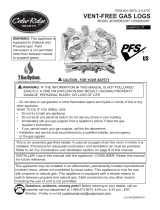
PLACING RATING TAG DECAL
0418GL009S
WARNING:
- Improper installation, adjustment, alteration, service, or maintenance can
cause property damage, personal injury, or loss of life. Refer to the owner's
manual provided with this heater. Installation and service must be performed
by a qualified installer, service agency, or the gas supplier.
- For installation in a solid-fuel burning fireplace only. The fireplace chimney
must have a permanent vent opening to atmosphere of not less than 50
square inches.
- A fireplace screen must be in place when the appliance is operating and,
unless other provisions for combustion air are provided, the screen shall
have an opening(s) for introduction of combustion air.
- Any glass doors shall be opened when the appliance is in operation.
Company Name
Street
City, State, ZIP
Serial Number:
Log Size
18’’ Vented
24’’ Vented
30’’ Vented
Height
19’’
19’’
20’’
Depth
15’’
15’’
15’’
Front Width
24’’*
30’’*
36’’*
Rear Width
20’’
26’’
32’’
Complies with ANSI Z21.84-2012, Standard
for Manually lighted, Natural Gas Decorative
Gas Appliances for Installation in Solid-Fuel
Burning Fireplaces.
Complies with ANSI Z21.60-2012, Standard
for Decorative Gas Appliances for Installa-
tion in Solid-Fuel Burning Fireplaces when
the LP Conversion Kit is installed by a
qualified technician.
Minimum Fireplace Size
*Important: If adding a Liquid Propane Conversion Safety Pilot Kit to the burner,
8" needs to be added to the front width dimension.
Model
Input Rating
Gas Type
Ignition Type
Max. Inlet Pressure
Min. Inlet Pressure
Normal Pressure
GLV024
45,000 BTU/hr
GLV030
55,000 BTU/hr
GLV018
35,000 BTU/hr
LP
Piezo Ignitor
14’’ WC
11’’ WC
11" WC
LP
Piezo Ignitor
14’’ WC
11’’ WC
11" WC
LP
Piezo Ignitor
14’’ WC
11’’ WC
11’’ WC
This appliance was converted on _____________________ (Day-Month-Year) to LP Gas
with Kit Model# by _____________________________________________________
(Name, Address of Company making this conversion), which accepts the responsibility that
this conversion has been properly made.
0418GL009S
WARNING:
- Improper installation, adjustment, alteration, service, or maintenance can
cause property damage, personal injury, or loss of life. Refer to the owner's
manual provided with this heater. Installation and service must be performed
by a qualified installer, service agency, or the gas supplier.
- For installation in a solid-fuel burning fireplace only. The fireplace chimney
must have a permanent vent opening to atmosphere of not less than 50
square inches.
- A fireplace screen must be in place when the appliance is operating and,
unless other provisions for combustion air are provided, the screen shall
have an opening(s) for introduction of combustion air.
- Any glass doors shall be opened when the appliance is in operation.
Serial Number:
Log Size
18’’ Vented
24’’ Vented
30’’ Vented
Height Depth Front Width Rear Width
Complies with ANSI Z21.84-2012, Standard
for Manually lighted, Natural Gas Decorative
Gas Appliances for Installation in Solid-Fuel
Burning Fireplaces.
Complies with ANSI Z21.60-2012, Standard
for Decorative Gas Appliances for Installa-
tion in Solid-Fuel Burning Fireplaces when
the LP Conversion Kit is installed by a
qualified technician.
Minimum Fireplace Size
*Important: If adding a Liquid Propane Conversion Safety Pilot Kit to the burner,
8" needs to be added to the front width dimension.
Company Name
Street
City, State, ZIP
WARNING: Information contained in the gures on this page may not be accurate or updated information.
DO NOT use any information inside of these gures for installation or technical purposes. They are only to be
used as a visual aid of how to place the decal.
After installing your new Kit #SPK100, you will need to update the information that is included on your decora-
tive/vented appliance by applying the included decal:
1. Locate the Rating Tag Decal in the Kit #SPK100packaging (See Figure 0.1)
2. Locate the Rating Tag hanging from the vented appliance (See Figure 0.2)
3. Rating Tag Decal will go where the white box is (See Figure 0.3)
4. Peel off and stick the Rating Tag Decal so it looks like Figure 0.4
5. Fill in date of conversion and name & address of company making the conversion on the
newly applied decal
Fig 0.1
Fig 0.2 Fig 0.3 Fig 0.4
Model
Input Rating
Gas Type
Ignition Type
Max. Inlet Pressure
Min. Inlet Pressure
Normal Pressure
GLV024
45,000 BTU/hr
GLV030
55,000 BTU/hr
GLV018
35,000 BTU/hr
LP
Piezo Ignitor
14’’ WC
11’’ WC
11" WC
LP
Piezo Ignitor
14’’ WC
11’’ WC
11" WC
LP
Piezo Ignitor
14’’ WC
11’’ WC
11’’ WC
This appliance was converted on _____________________ (Day-Month-Year) to LP Gas
with Kit Model# by _____________________________________________________
(Name, Address of Company making this conversion), which accepts the responsibility that
this conversion has been properly made.

19
PLACING LIGHTING TAG DECAL
1. STOP! Read the safety information on all the labels.
WARNING: BE SURE THAT THE CHIMNEY DAMPER IS FULLY OPEN.
2. Turn manual shutoff valve clockwise to the "OFF" position.
3. Wait five (5) minutes to clear out any gas. Then smell for gas, including near the floor.
If you smell gas, STOP! Follow "B" in the safety information above on this label. If you
don't smell gas, go to the next step.
4. Place a burning match on the surface of the burner embers. Do not hold match in hand.
5. Slowly turn manual gas shutoff valve ON. The gas should ignite in five (5) seconds. If
there is no ignition within ten seconds of laying the match down, set manual shutoff valve
to OFF and repeat steps 1-5 again.
TO TURN OFF GAS TO APPLIANCE
1. Gently press and turn the gas control knob in a clockwise direction to the
"FULL OFF" position.
FOR YOUR SAFETY
READ BEFORE LIGHTING
LIGHTING INSTRUCTIONS
VENTED GAS LOG SET
WARNING: If you do not follow these instructions exactly, a fire or explosion may result
causing property damage, personal injury or loss of life.
A. This appliance must be lighted by hand each time it is used. When lighting, follow
these instructions exactly.
B. BEFORE LIGHTING smell all around the appliance area for gas. Be sure to smell
next to the floor because some gas is heavier than air and will settle on the floor.
WHAT TO DO IF YOU SMELL GAS
• Do not try to light any appliance.
• Do not touch any electrical switch; do not use any phone in your building.
• Immediately call your gas supplier from a neighbor's phone. Follow the gas
supplier's instructions.
• If you cannot reach your gas supplier, call the fire department
C. Use only your hand to push in or turn the gas control knob. Never use tools. If the
knob will not push in or turn by hand, don't try to repair it, call a qualified service
technician. Forced or attempted repair may result in fire or explosion.
D. Do not use this appliance if any part has been under water. Immediately call a
qualified service technician to inspect the appliance and to replace any part of the
control system and any gas control which has been under water.
TO TURN OFF GAS TO APPLIANCE
LIGHTING INSTRUCTIONS
SAFETY PILOT KIT
IMPORTANT:
LOCATE HANGING TAGS ON THE APPLIANCE.
PEEL OFF AND PLACE OVER “LIGHTING INSTRUCTIONS” SECTION
OF THE SIMILAR HANGING TAG, BUT NOT OVER THE
“FOR YOUR SAFETY” SECTION.
REFERENCE PAGE 6 OF MANUAL
FOR FURTHER DETAILED INSTRUCTIONS.
1. STOP! Read the safety information as noted above.
WARNING: BE SURE THAT THE CHIMNEY DAMPER IS
FULLY OPEN.
2. Read all warnings and safety information in the manual
3. Locate the valve on the side of the unit, and push the gas control knob in
1. Push in the control knob slightly and turn all the way clockwise , so the white dot is
pointing to the "OFF" position.
slightly (DO NOT FORCE) and turn clockwise to OFF (See Fig. 5).
the safety instructions as noted above "WHAT TO DO IF YOU
SMELL GAS". If you do not smell gas, continue onto the next step.
5. Slightly push in, and turn the control knob counterclockwise so the
white dot on the control knob lines up with "PILOT" (See Fig. 6)
7. With control knob depressed, repeatedly push down the
4. Wait five (5) minutes to clear out any gas. If you smell gas, STOP! Follow
6. Push firmly and hold the control knob in fully and hold
piezo ignitor until the pilot lights.
The pilot is visible, at the back of the burner on the valve side (See Fig. 7).
• Do not attempt to light the pilot by hand.
Fig. 7
Fig. 5
Fig. 6
8. Keep control knob depressed for (30) seconds after pilot lights.
Release control knob.
• If the control knob does not pop up when released,stop and immediately
call a qualified service technician or gas supplier.
• If the pilot will not stay lit after several times, turn the gas control knob to
“OFF”, and call your service technician or gas supplier
9. Ensure the pilot is lit. Turn the gas control knob counterclockwise to
the "ON" position (See Fig. 8)
terclockwise to open or clockwise to close, as desired.
Fig. 8
WARNING: Information contained in the gures on this page may not be accurate or updated information.
DO NOT use any information inside of these gures for installation or technical purposes. They are only to be
used as a visual aid of how to place the decal.
After installing your new Kit #SPK100, you will need to update the information that is included on your decora-
tive/vented appliance by applying the included decal:
1. Locate the Lighting Tag Decal in the Kit #SPK100 packaging (See Figure 0.5)
2. Locate the Lighting Tag hanging from the vented appliance (See Figure 0.6)
3. Lighting Tag Decal will go where the white box is (See Figure 0.7)
4. Peel off and stick the Lighting Tag Decal so it looks like Figure 0.8
Fig 0.6 Fig 0.7 Fig 0.8
Fig 0.5
/