
SAVE THESE INSTRUCTIONS
CONSERVER CES INSTRUCTIONS
GUARDE ESTAS INSTRUCCI ONES
Cabinet Water Softener
Adoucisseur d’eau cabinet
Suavizador de agua cabinet
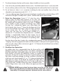
CAUTION: Before using water
softener, read this manual and
follow all safety rules and
operating instructions.
MISE EN GARDE: Avant
d’employer votre adoucisseur
d’eau, lisez ce manuel et suivez
toutes les règles de sécurité et
les consignes d’utilisation.
PRECAUCIÓN: Antes de usar
el suavizador de agua, lea este
manual y siga todas las reglas
de seguridad e instrucciones de
funcionamiento.
VWS296GR
Installation, Use & Care Guide
Guide d’installation, utilisation et d’entretien
Manual de uso, cuidado e instalación
190507

Table of ConTenTs:
Preinstallation Instructions Page 1 - 2
Bypass Assembly Page 3 - 5
Installation Instructions Page 5 - 7
Programming Procedures Page 8 - 11
Start-up Instructions Page 12
Troubleshooting Guide Page 13 - 14
Replacement Parts Page 15 - 16
Water Softener Warranty Page 17
Your Water Test
Hardness gpg
Iron ppm
pH number
Nitrates ppm
Manganese ppm
Sulphur yes/no
Total Dissolved Solids
Vitapur
®
Water Softeners are precision built, high quality products. These units will deliver softened water
for many years to come, when installed and operated properly. Please study this manual carefully and
understand the cautions and notes before installing. This manual should be kept for future reference. If you
have any questions regarding your water softener, additional assistance can be found on our website at:
www.ghpgroupinc.com or by calling our customer service line at:
1-877-447-4768, Monday to Friday from 8:00 AM to 4:30 PM (CST)
speCifiCaTions:
MODEL # VWS296GR
Grain Capacity 30,000
Control System Electronic on Demand
Salt Storage Capacity 165.4 lbs / 75.0 kg
Unit Dimensions (W x D x H) 19.5” X 14.7” X 43.7” • 49.5 cm X 36.0 cm X 111.0 cm
Unit Weight 92.6 lbs/42.0 kg
Plumbing Connection Size ¾” MNPT
Min/Max Water Pressure 30 - 100 psi (CAN) • 30-125 psi (USA)
Regeneration Time of Day Adjustable
Electrical Requirements 120V / 60Hz / 12V DC
Salt Consumption/Cycle at MED salt setting 8.3 lbs / 3.8 kg
Operating Water Temperature Range 4.0 C – 40.0 C
Resin Quantity 0.92 cubic ft / 26.0 L
Service Flow Rate 8.8 U.S.Gal/min

1
preinsTallaTion insTruCTions
General:
• Observe all warnings that appear in this manual.
• Keep media tank in the upright position. Do not turn upside down or drop. Turning the tank upside
down will cause media (resin) to enter the valve.
• Operating ambient temperature is between 39.2 ˚F (4 ˚C) and 104 ˚F (49 ˚C).
• Operating water temperature is between 39.2 ˚F (4 ˚C) and 104 ˚F (40 ˚C).
• Working water pressure range is 30 psi to 125 psi (USA) and 30 psi to 100 psi (Canada) .
• Follow state and local codes for water testing. Do not use water that is microbiologically unsafe or of
unknown quality.
• When filling the media tank with water, do not open main water valve completely. Fill tank slowly to
prevent media from exiting the tank.
• Allow welded or soldered parts to cool and set before installing any plastic parts.
Location Selection:
Location of a water treatment system is important. The following conditions are required:
• As close as possible to the incoming main water supply.
• As close as possible to the floor drain.
• To soften all water in the home, install the softener to the main water supply inlet before the in-line
filtration system (if applicable) and before all other plumbing connections, except outside water lines.
Outside faucets should remain on hard water to avoid wasting conditioned water and salt.
• Connect the softener to the main water supply line ”before” the water heater.
• Level platform on floor.
• Allow floor space to access equipment for maintenance and adding regenerant (salt) to tank.
• Constant electrical supply to operate controller.
• Total minimum pipe to water heater of 10 ft. to prevent backup of hot water into system.
• Water line connections with shutoff valve.
• Must meet any local or state codes for site of installation.
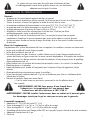
CAUTION: DO NOT run hot water through the softener.
Temperature of water passing through the softener must be less
than 104 ˚F/ 40 ˚C.
CAUTION: DO NOT install the softener in a location where it
can freeze. Damage caused by freezing is not covered by the
warranty.
Kit Includes:
• 120-V/60-Hz AC adapter plug (12V DC Output).
• ½” I.D. Drain hose (4.1 m / 13.5ft) and clamp.
• ½” I.D. Overflow hose (2.1 m / 6.9ft) and clamp.
• Bypass Assembly with ¾” NPT male threads for inlet and outlet ports and clips.
• ¾” short inlet adapter.
• Neck wrench.
The system is not intended to be used for treating water that is microbiologically
unsafe or of unknown quality without adequate disinfection before or after the system

2
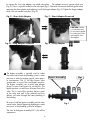
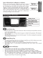
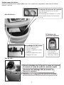
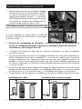
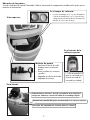
Parts Location:
When you open your Cabinet Softener carton, you will find the components located in the areas shown below:
Bypass Assembly:
• Wrench for valve neck
• One bypass gasket
• Complete bypass with
connectors and clips
• Inlet valve adapter
• Power Adapter
Inside Brine Tank:
• Two ½” drain tubing with two clamps:
valve drain pipe 4.1m/13.5ft long
Brine tank overflow hose 2.1m/6ft long
LCD display connector (to be connected to top cover)
Connect
3
/
8
“ white tubing from valve to
brine tank via quick connect elbow
Power adapter connection to valve
• LCD display wire
(To be connected
to softener head
connection below)
Top View:
Side View:
Inside Top Cover:

3
Tools Required:
• Flat head screw driver
• Pliers
• Tape Measure
• Pipe Cutter
• Propane Torch
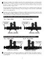
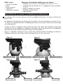
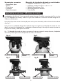
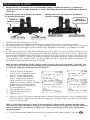
ValVe adapTer and bypass assembly
The ¾” valve adapters that connect the bypass assembly to valve are shown in the Fig A & Fig. B.
The inlet & outlet adapters in Fig B are installed on the water softener valve at the manufacturing facility.
These valves allow you to connect the bypass assembly with the inlet and outlet ports in the downward
direction Fig. D.
Fig. A shows a longer inlet water adapter. This means that the shorter inlet adapter has to be removed and
replaced with the longer inlet adapter if you want the bypass assembly with the inlet and outlet ports facing
upwards. (Fig.C)
Fig. C. The longer inlet adapter is in the box containing the bypass assembly, power adapter and wrench for
neck spacer removal (if needed).
Additional Installation Materials Not Supplied:
• ¾” Copper adapter, or ½” to ¾” copper adapter
• ¾” Pex pipe adapter or ½” to ¾” pex pipe adapter
• Lead free solder & Flux
• Emery cloth or steel wool
• Teflon Tape
Outlet Adapter
Outlet Port Outlet PortInlet Port Inlet Port
Outlet AdapterInlet Adapter Inlet Adapter
Fig. A
Fig. C
Fig. B
Fig. D
1.

4
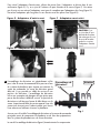
To remove the short inlet adapter use needle nose pliers. The adapter unscrews counter clock wise
(Fig. E). There is a gasket inside the inlet valve port (Fig F). Please do not remove the black gasket when
removing the short adapter and replacing it with the longer adapter (Fig. G). Tighten the longer adapter
clock wise with needle nose pliers (Fig. H).
The bypass assembly is typically used to isolate
the control valve from the plumbing system’s water
pressure in order to perform control valve repairs
or maintenance. The ¾” full flow bypass valve
incorporates a service flow and bypass position.
The bypass assembly uses a piston type plunger
design to move from bypass to service flow. The
bypass position is used to turn off water flow to the
valve. The in service flow position delivers water
to the valve and tank to be softened and then
delivers soft water through the water plumbing in
the building.
Be sure to install the bypass assembly onto the main
control valve, before beginning plumbing or make
provisions in the plumbing system for a bypass.
The view of the bypass assembly (FIG. I) lists all the
components.
Fig. E - Short Inlet Adapter
Fig. H - Long Adapter installed
Fig. F - Short Adapter Removed
Fig. G - Long Adapter
CAUTION: Gasket
is in inlet valve port.
Do not remove gasket
from valve port when
removing the short
inlet adapter.
Bypass Assembly
Clips
2.
Fig. I

5
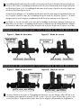
bypass assembly (wiTh inleT and ouTleT porTs upward)
The inlet and outlet ports on the bypass assembly are ¾” male NPT threads. The couplers to attach ¾”
and ½” pex pipe or ¾” and ½” copper pipe are not provided. This can be purchased at any hardware
or plumbing store.
The bypass assembly can be installed on the valve with the intake and outlet ports in the downward or
upward direction. The bypass assembly with the inlet and outlet ports facing in the downward direction
are shown in Figures J & K. The bypass assembly with the inlet and outlet ports facing in the upward
direction are shown in Figures L & M.
The piston plunger head on the bypass assembly with the red circle is completely pushed in against the
assembly body when in bypass mode (Fig L). The piston plunger with the red circle is fully extended
when in service mode (Fig. M).
The arrows on the inlet and outlet ports of the bypass assembly show the direction of water flow to the
valve. The bypass assembly is labeled with white arrows showing the direction of water flow when the
inlet and outlet ports are facing in the upward or downward direction.
Fig. J - Bypass Mode
Fig. L - Bypass Mode
Fig. K- Service Mode
Fig. M - Service Mode
bypass assembly (wiTh inleT and ouTleT porTs downward)
Piston Plunger
(PUSH IN)
Piston Plunger
(PUSH IN)
Piston Plunger
(PULL OUT)
Piston Plunger
(PULL OUT)
Outlet Port
Outlet Port Outlet Port
Outlet Port
Inlet Port
Inlet Port Inlet Port
Inlet Port
3.
4.
5.

6
The clips connecting the bypass assembly to the valve are inserted in the downward direction when the
inlet and outlet ports are facing downwards. The locking clips are inserted in the upwards direction from
the bottom when the inlet and outlet ports are upwards.
When the bypass assembly is in service mode the soft water is delivered to the building. During
regeneration cycle hard water is delivered to the water softener while also providing hard water to the
building distribution system.
bypass assembly wiTh inleT and ouTleT
porTs faCing upwards)
bypass assembly wiTh inleT and ouTleT
porTs faCing downwards)
Locking Clips
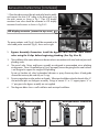
insTallaTion insTruCTions
Assembling the Water Softener:
CAUTION: When maneuvering
the resin tank into the cabinet
do not attempt to lift the resin
tank by the top cover.
Rotate the valve and resin tank on the
ground to maneuver it into place for
the installation.
Fig. N Fig. O
Locking Clips
6.
7.
8.
Please check that the flow
meter cable is connected on
the valve outlet port.

7
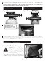
2. Bypass Assembly Connection: Install the bypass valve onto the main control
valve using the H clips before beginning plumbing. (See Fig. N or O)
3. The installation of the water softener must be carried out in accordance with state, local and provincial
plumbing codes.
4. The control valve, fittings and bypass assembly are designed to accommodate minor plumbing
misalignments. There is a small amount of “give” to properly connect the piping but the water softener
is not designed to support the weight of the plumbing.
Do not use Vaseline oils, other hydrocarbon lubricants or spray silicone anywhere. A food grade
silicone lubricant may be used only on O-rings.
5. Do not use pipe dope or other sealants on threads. Teflon tape should be used on the threads of the ¾”
inlet and outlet ports on the bypass assembly. Fittings to connect ¾” or ½” copper pipe or ¾” or
½” pex pipe to the bypass assembly are not supplied.
6. The diagrams below show a well installation and municipal installation.
The power adapter cord (Fig 4.) should be connected to the
valve cable power connector (Fig 5.) shown on the right:
Water TechnologiesWater Technologies
Municipal Water InstallationWell Water Installation
Fig 1.
Fig 2.
Fig 4.
Fig 3.
Fig 5.
LCD display connector (connect to top cover)
insTallaTion insTruCTions (ConTinued)
1. Place the cabinet around the tank and valve head assembly
and connect the white 3/8” tubing to the brine tank using
the quick connect as shown in Fig 1. Then LCD display
connector from valve should be connected to LCD display
connector from the cover as shown in Fig 2 & 3.

8
7. The distance between the drain and the water softener should be as short as possible.
8. Since salt must be periodically added to the brine tank, it should be located where it is easily accessible.
9. Do not install any softener with less than 10ft of piping between the outlet and the inlet of a water heater.
10. Do not locate unit where it or its connections (including the drain and overflow lines) will ever be
subjected to room temperature under 34˚F / 1.1˚C.
11. If you are soldering copper fittings that connect to the bypass assembly make sure that the fitting is NOT
connected to the bypass assembly which is plastic. The heat could melt the plastic threads.
12. Drain Line Connection: Connect ½” I.D. drain line with a
clamp to drain line barb fitting connector on the valve. The
plastic barb fittings for drain line and brine line are designed to
be screwed and unscrewed by hand to the valve. If leakage
occurs carefully use pliers to tighten until leakage stops. When
the drain line is elevated but empties into a drain below the
level of control valve, form a 7” loop at the discharge end of the
line so that the bottom of the loop is level with drain connection
on the control valve. This will provide an adequate anti-
siphon trap. The drain line can be piped overhead to a
maximum of 3 ft provided that adequate pressure is available
(40-60psi is recommended). Where the drain empties into an
overhead sewer line, a sink-type trap must be used. Run drain
tube to its discharge point in accordance with plumbing codes.
Run drain hose to floor drain, laundry tub or standpipe taking measures to secure the hose to prevent
“whipping“ action during regeneration mode since drain line hose is under pressure during back washing
and rinse cycles. Always allow a minimum air gap of 1 1/2” between the end of drain hose and drain
to prevent sewer back up.
13. Overflow Line Connection:
An overflow drain line is recommended where the brine overflow could
damage furnishings or the building structure. Your softener is equipped with
brine tank safety valve which greatly reduces the chance of an accidental
brine overflow. In the event of a malfunction, however, an overflow line
connection will direct the “overflow” to the drain instead of spilling on the
floor where it could cause damage. The fitting is an elbow on the back side
of the brine tank. Attach a length of 2.1 m ½” I.D. tubing to the barb elbow
fitting and run to drain. Do not elevate the overflow line higher than 3”
below bottom of overflowing fitting. Do not “tie” this tube into the drain line
of the control valve. Overflow line must be a direct, separate line from
overflow fitting to drain, sewer, or tub. Allow an air gap as per drain line
instructions.
CAUTION: NEVER insert a drain line into a drain, sewer line or trap. Always
allow an air gap between the drain line and the wastewater to prevent
thpossibility of sewage being back- Siphoned into the water softener.

9
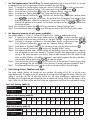
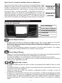
programming proCedures
Control Panel:
Display Screen
Menu/Confirm Key
Manual/Return Key
Down Key
Up Key
Menu/Confirm Key:
• The menu/confirm key is used to enter into the menu. When in the menu press Up and Down arrow keys
to show each parameter value.
• When in the menu press the menu/confirm key again to indicate that the parameter will be adjusted.
The value flashes.
• After setting the parameter press the menu/confirm key again. This confirms accepting the new parameter
and returning to the main menu.
Manual/Return Key:
• Pressing the Manual/Return Key when not in the menu state allows you to finish working in your current
menu and going to an alternative menu immediately.
• The Manual/Return key allows you to go from the Advance Settings back to the main menu.
• When display screen is in service mode the Manual/Return key can be used to start a manual
regeneration.
Down and Up Keys:
• The Up and Down arrow keys allow you to scroll down and up through the menu.
• The Up and Down arrow keys allows adjusting parameters when in the set-up menu.
• When the Up and Down Keys are pressed together for 5 seconds the set-up menu is unlocked.
• When pressing the Down and Up keys to adjust a parameter a number is changed incrementally per
press. When holding the key for longer than 1.5 second allows you to scroll through numbers at the
rate of 1 number every 0.2 seconds. Holding the key longer than 3 seconds advances the number
change at a rate of 20 per 0.2 seconds for rapid scrolling.
Types of Salt and Level to Maintain in a Softener:
The brine well in the brine tank is labeled with red lines for minimum
and maximum level for salt loading inside the cabinet. Always maintain
the salt level between the minimum and maximum levels to prevent
“bridging”. The types of salt that should be used include: solar or pellets.
If pellets are used a cleaning of the brine tank is recommended every six
months. A sodium alternative to soften water is to use Potassium Chloride
which is 99% sodium free. This reduces sodium levels in softened water
and chloride discharges into the environment.
Maximum
Salt Level
Minimum
Salt Level

10
The ONLY Parameters Set By Consumer (or plumber):
a) Language
b) Set Clock
c) Under Advanced Setting
i) Set the regeneration time” Recharge Time”
ii) Capacity under “Residual Water”.
iii) Salt Setting Low, Medium and High Salt Setting
CAUTION: DO NOT CHANGE ANY OTHER PARAMETERS BEYOND THE 5 LISTED
ABOVE. IT WILL ADVERSELY AFFECT THE PERFORMANCE OF THE WATER SOFTENER
The programming for the water softener is set-up with the default settings listed in the table below.
The ONLY parameters that should be accessed by plumber/consumer are shown in the table as “Adjust”.
Main Menu Display Default Settings Access To Parameters
Set 12/24 Hour Clock 12 hour clock Not Adjustable
Set Clock 12:00 A.M. Adjust
Water Used Today Display on Daily Water Consumption Display
Average Water Use in Week Display On Average Weekly Water Consumption Display
Set GAL/L/Cubic Meters GAL Not Adjustable
Advance Settings To Get Into Advanced Settings-Sub Menu
Sub Menu Advanced Settings Display
Set Work Mode A-11 Not Adjustable
Set Recharge Time (Regeneration Time) 2:00 A.M. Adjust
Set Residual Water (Capacity) 1306 U.S. Gallons @ 20 grains/U.S. Gallon Adjust
Set Interval Wash F00 Not Adjustable
Set Back Wash 2 min Not Adjustable
Set Brine & Rinse 50 min Adjust only if salt setting is being changed
Set Brine Refill 2 min Adjust only if salt setting is being changed
Set Fast Rinse 6 minutes Not Adjustable
Set Max Days/Recharge 14 days Not Adjustable
Set Output Signal b-01 Not Adjustable
1. Set The Language: The default setting for the language is English. If you do not want to change
the language proceed to set the clock. There are 7 languages to choose from consisting of French,
Chinese, Spanish, German, Italian, English and Russian.
Step 1. To change the language from English to any of the other 6 languages press the Menu/Confirm
and Manual/Return key simultaneously within 2 seconds of plugging in the power
adapter.
Step 2. Scroll down to the language preference using the down arrow
Step 3. Press the menu/confirm key
2. Set The Clock: The time of day only needs to be set up during initial set up and after extended power
outage (3 days). The battery back-up lasts up to 72 hours after a power outage. The default setting
on the clock is 12.00 a.m.
Step 1. Unlock program by pressing the down and up arrows together and hold for 5 seconds
if the screen is locked. If not locked proceed to Step 2.
Step 2. Press the Menu/Confirm Key once to enter the main menu
Step 3. The Clock Setting is the second item on the main menu.
Step 4. Press the Menu/Confirm Key and the hour in the clock setting will start flashing.
Step 5. Use the down or up arrows to scroll to the correct hour. The AM and PM will change
as hours advance from morning to afternoon.
Step 6. Press the Menu/Confirm Key and the minutes will start flashing. Use the down and up
arrows to adjust to the correct minute setting.
Step 7. Press Menu/Confirm Key and menu will return to “Set Clock” in the main menu.
Step 8. Press Manual/Return Key to proceed back to the In Service Display screen if no other
parameters are going to be changed. If continuing to change other parameters scroll to desired
parameter using the down arrow in the main menu without going back to the In Service
Display Screen.

11
Hardness gpg 10 15 20 25 30 35 40 45 50 55 60 65 70
Soft Water Available
(U.S. Gallons)
2250 1500 1125 900 750 643 563 500 450 409 375 346 321
Hardness gpg 10 15 20 25 30 35 40 45 50 55 60 65 70
Soft Water Available
(U.S. Gallons)
2613 1742 1306 1045 871 747 653 581 523 475 436 402 373
Hardness gpg 10 15 20 25 30 35 40 45 50 55 60 65 70
Soft Water Available
(U.S. Gallons)
2900 1933 1450 1160 967 829 725 644 580 527 483 446 414
Medium Salt Setting (table B):
Low Salt Setting (table A):
High Salt Setting (table C):
3. Set The Regeneration Time Of Day: The default regeneration time is set at 2:00 AM. If you want
to change the time for the regeneration cycle to start follow the steps below.
Step 1. If starting at In-Service display screen press Menu/Confirm key to switch to main menu.
Step 2. Scroll down to “Advance Settings” in the main menu using the down arrow .
Step 3. Press the Menu/Confirm Key to enter the “advance settings” sub menu.
Step 4. Scroll down to “Setting Recharge Time” using the down arrow key .
Step 5. Press the Manual/Confirm Key . The hour will start flashing. Use the down and up arrow
keys to scroll to the correct hour. The AM and PM will change as hours advance from
morning to afternoon. When the correct hour is chosen press Menu/Confirm Key and the
flashing will advance to the minutes. Use the down and up arrow keys to advance to
the correct minutes.
Step 6. Press the Menu/Confirm Key will bring you back to “Setting Recharge Time”.
Step 7. Press the Manual/Return Key twice to bring you back to the In Service Display screen.
4. Set Capacity (amount of soft water available):
The default capacity is 1306 U.S. Gallons @ 20 grains/U.S. Gallon at medium salt setting.
Step 1. If starting at In-Service menu press Menu/Confirm key to switch to the main menu. If
continuing in the main menu scroll down to “Advance Settings” using the arrow keys
Step 2. If already in sub menu scroll down to “Residual Water Setting” using the arrow keys
Press the Menu/Confirm Key to enter the “Advance Settings” sub menu.
Step 3. Scroll down to “Residual Water” in the sub menu set up using the down arrow key .
Step 4. Press the Manual/Confirm Key to enter the “Residual Water” setting.
Step 5. The capacity residual water volume number will be flashing. Input the water volume capacity
that corresponds to your water hardness. The water hardness was determined by you during
testing of the water that enters your facility. Refer to table on top of the valve under the top
cover or table B below. Use table to determine water volume capacity based on hardness.
Use the down and up arrow keys to input the volume.
Step 6. Press the Manual/Confirm Key . This will return you to the sub menu. If continuing to set up
other parameters like salt setting stay in the sub menu. If exiting sub menu proceed to Step 7.
Step 7. Press Manual/Return Key twice to exit the set-up menu to the In-Service Display.
5. Salt Setting At Low, Medium and High:
The water softener default salt settings are at a medium salt setting of 8.0 lbs. of salt for every
regeneration cycle. The option exists for setting the salt setting to low and high salt setting. When the salt
setting is set to low (6.0 lbs. of salt) there will be less soft water available per regeneration cycle.
Therefore you will regenerate more frequently than at medium salt setting. When the salt setting is set at
high (14 lbs. of salt) there will be more soft water per regeneration cycle than low and medium setting.

12
Salt Setting Brine & Rinse (time - min:sec) Brine Refill (time - min:sec)
Low salt setting 37:00 1:30
Medium Salt Setting 50:00 2:00
High Salt Setting 54:30 2:30
The time settings for Brine & Rinse and Brine Refill are in the tables below at low, medium and high salt setting.
Time Settings For Brine Refill And Brine & Rinse At Low Salt Setting (table D):
If changing the salt setting to low or high salt setting, the first step is to change the capacity (Amount of Soft Water Available) by
following the procedure in Section 4 “Set Capacity”. Use the tables A or C on pg 11.
To change the salt setting from the default medium salt setting to low or high salt setting the times for Brine & Rinse and Brine
Refill have to be changed. Follow the steps below.
Step 1. If starting at In-Service menu press Menu/Return key to switch to the main menu. If continuing in the main menu
scroll down to “Advance Settings” using the arrow keys.
Step 2. Press the Menu/Confirm Key to enter the “Advance Settings” sub menu.
Step 3. Scroll down to “Brine and Rinse” in the sub menu set up using the down arrow key .
Step 4. Press the Menu/Confirm Key and the minutes in the “Brine and Rinse” will start flashing. Use the appropriate values
in Table D to adjust the times if you prefer low salt setting or high salt setting.
Step 5. Use the down or up arrow keys to scroll to the correct minutes.
Step 6. Press the Menu/Confirm Key and the seconds will start flashing. Use the appropriate values in Table D to adjust the
times for your preference of low or high salt setting. Use the down or up arrow keys to adjust to the correct
minute setting.
Step 7. Press the Menu/Confirm Key and menu will return to the main menu “Brine and Rinse”.
Step 8. Scroll down to “Brine Refill”.
Step 9. Press the Menu/Confirm Key and the minutes in the “Brine Refill” will start flashing. Use Table D to select the time
for your preference of low or high salt setting.
Step 10. Use the down or up arrow keys to scroll to the correct minutes.
Step 11. Press the Menu/Confirm Key and the seconds will start flashing. Use table D to select the seconds. Use the down
and up arrow keys to adjust to the correct seconds setting.
Step 12. Press the Menu/Confirm Key and menu will return to set-up menu “Brine Refill”.
Step 13. Press Manual/Return Key twice to proceed back to the In Service Display screen if no other parameters are
going to be changed.
6. Calendar Day Override:
The calendar day override has been set to 14 days. This means if the water softener water capacity is not used up in 14 days it will
regenerate automatically to help prevent resin fouling.
7. Manual Regeneration:
1. Sometimes there is a need to regenerate the system sooner than when the system call for it, usually referred to as manual
regeneration. There may be a period of heavy water usage because of guests or a heavy laundry day. To initiate a manual
regeneration immediately, press the Manual/Return key . The control valve will cycle through the following regeneration cycles:
Backwash • Brine Draw & Slow Rinse • Fast Rinse • Fill Brine Tank • Back to In Service
Note: Regeneration cycle will take approximately 54 minutes to complete.
2. When the regeneration cycles are completed the valve will return to the in-service mode.
3. The only way to cancel a manual regeneration is to cycle fast through the steps by pressing the
Manual/Return Key repeatedly after every cycle until the valve returns to service mode.
8. Power Loss:
If the power outage exceeds 3 days (72 hours) the clock will need to be reset. When the power is turned on the clock figure
will flicker continuously. This reminds owner to reset the time. All other parameters will not need to be reset.
9. Hard Water Notice:
During softener regeneration cycle, only hard water will be available in the facility.
10. Error Message:
If the errors E1, E2, E3 or E4 show on the display screen contact the dealer for assistance.

13
2. Turn on the main water valve in the house.
3. Fully open a cold water faucet-preferably a laundry sink or bathtub with no aerator.
4. This allows the removal of any debris from piping which may have occurred during installation. Check for leaks.
5. Turn off the main water valve in the house. Keep the laundry sink faucet or bathtub faucet with no aerator open.
6. The system is now ready for filling the resin tank with water. For the purpose of filling the softener resin tank the bypass
assembly piston rod has to be pushed to the “In Service” position. Turn on the main water line SLOWLY to expel air in the
resin tank and fill the resin tank with water. Check for any leaks at all connection points. When the laundry sink or bathtub
faucet is on it eliminates any air bubbles in the resin tank. Note the colour of the water coming from the faucet or laundry tub
faucet. If discoloured let water run until clear.
NOTE: At no time should there be “large particles” of media noticed at a faucet which you opened. If this is seen immediately
shut off the water and bypass assembly as this could be an indication of a distributor failure. Contact manufacturer or
distributor for assistance.
7. When the bypass assembly is in service mode
and the display screen shows the following
every 5 seconds:
i) Mode (A-11) Volume Delayed/Up
Flow. The regeneration is by up flow.
Regeneration will begin when Soft
water capacity (Volume U.S.
Gallons) is depleted and time
reaches the regeneration time.
ii) In-service regeneration time
iii) In-service soft water available
iv) In-service flow rate
8. Add 2.6 U.S. Gallons of water to the brine tank during initial start-up only. This will allow for the first regeneration brine
solution. After the first regeneration the brine tank refills automatically for future regenerations.
NOTE: If too much water is put into the brine tank during softener start- up it could result in salty water complaint after the
first regeneration. During the first regeneration the unit will draw out the initial volume of brine solution and refill it with
the correct volume of water in the brine tank for the next regeneration.
9. Press the manual/return key to start the manual regeneration cycle to check for leaks.
1. After installation is completed, push the piston plunger on the bypass assembly to bypass mode.
The head of the piston plunger is identified with a red circle.
sTarT-up insTruCTions
Bypass assembly with inlet ports downward Bypass assembly with inlet ports upward
Plunger in
bypass mode
Plunger in
bypass mode
Outlet Port
Outlet Port
Inlet Port
Inlet Port

14
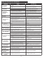
PROBLEM CAUSE SOLUTION(S)
1. Softener fails to
regenerate.
A. Power supply to unit has been interrupted. A. Check power supply.
B. Regeneration cycle set incorrectly. B. Reset regeneration cycles.
2. Regeneration time
is not correct.
A. Time of day not set correctly.
Check program and reset time of day.
B. Power failure lasted more than 3 days.
3. Softener supplies
hard water.
A. Bypass valve opened or leaking. A. Close or repair the bypass valve.
B. No salt in brine tank.
B. Add salt to the brine tank and maintain salt
level above water level.
C. Injector is plugged. C. Change or clean the injector.
D. Regeneration cycles not correct.
D. Set the correct regeneration cycles in the
program.
4. Unit uses too much salt.
A. Improper salt setting. A. Check salt usage and salt setting.
B. Excessive water in brine tank. B. See problem No. 6
5. Excessive water in
tank.
A. Too long refilling time. A. Reset correct refilling time.
B. Too much water in brine tank after brine draw.
B. Check the injector and make sure no foreign
material in brine tubing plugging flow.
C. Safety brine valve breakdown. C. Repair or replace safety brine valve.
6. Control Valve cycles
continuously.
A. Locating signal wiring breakdown. A. Check and connect locating signal wiring.
B. Controller is faulty. B. Replace the controller.
C. Time of regeneration steps were set to zero. C. Check program setting and reset.
7. Drain line flows
continuously.
A. Power loss when in backwash or fast rinse.
A. Adjust valve to service position or turn off
bypass valve and restart when power is back
on.
8. Salt water taste
in the soft water.
A. Foreign material in injector or injector fails to work. A. Clean and repair injector.
B. Brine valve cannot shut-off. B. Repair brine valve and clean it.
C. Time of fast rinse too short. C. Extend fast rinse time.
9. Water capacity
decreases.
A. Regeneration cycle not completed. A. Complete a full regeneration cycle.
B. Salt setting not adequate. B. Readjust brine draw time.
C. Softener setting for capacity not correct.
C. According to the test of outlet water, recount
and reset.
D. Raw water quality deterioration.
D. Regenerate unit manually then reset the
regeneration cycle.
10. Water capacity
decreases.
A. The wiring of front panel with controller fails to
work.
A. Change the cable between screen and control
panel.
B. Power adapter is wet or damaged. B. Check and replace the power adapter.
C. Electrical power supply interrupted. C. Check the power supply is on.
11. Nothing displays on
LED screen.
A. The wiring of front display panel with controller fails
to work.
A. Check and replace cable. Connecting display
screen to valve.
B. Power is cut off. B. Check the cables and main power supply.
12. Only “E1” shows on
the screen and is
flashing.
A. The line between the locating board and main
control board is damaged.
A. Replace cable between the locating board and
main control board.
B. Motor is damaged. B. Replace motor.
13. Only “E2” shows on
the screen and is
flashing.
A. The cable between the locating board and main
control board is damaged.
A. Replace wiring harness.
14. Only “E3” or “E4”
shows on the screen
and is flashing.
A. Control board is faulty. A. Replace control board.
TroubleshooTing guide

15
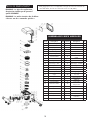
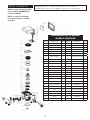
replaCemenT parTs:
Replacement parts can be purchased by checking our website at www.ghpgroupinc.com,
or by calling our customer service line at 1-877-447-4768, Monday to Friday from 8:00
AM to 4:30 PM (CST).
Item No. Description Quantity Item No Description Quantity.
1. Cover of Injector 1
26
Screw, Cross 4
2. Screw, Cross 2
27
Screw, Cross 4
3. Nozzle, Injector 1
28
Motor 1
4. Throat, Injector 1
29
Seal Ring 1
5. O-ring 2
30
Fixed Disk 1
6. Injector Body 1
31
Moving Disk 1
7. Seal Ring 1
32
Moving Seal Ring 1
8. Plug 1
33 Shaft 1
9. Adjust Screw 1
34
Anti-friction Washer 1
10. O-ring5*1.5 2
35 O-ring33.5*3.55 2
11. O-ring3.75*1.8 1
36 O-ring64*3.55 2
12. Screw, Cross 7
37
Fitting Nut 1
13. O-ring 2
38
Locating Board 1
14. Flat joint 1
39
Gear 1
15. pipe 1
40 Screw, Cross 1
16. O-ring25.8*2.65 5
41
Display Board 1
17. O-ring73*5.3 1
42
Wire for Display Board 1
18. Seal Ring 1
43
Probe wire 1
19. Animated Connector 1
44
Dust Cover 1
20. O-ring21.89*2.62 2
45
Wire for Power 1
21. By-pass 1
46 Wire clip 2
22. Impeller Group 1
47
Screw, Cross
2
23. O-ring19*2.65 1
48
Control Board 1
24. Impeller 1
49
Wire for Locating Board 1
25. Valve Body 1
50
Front Cover 1
VWS296GR BODY ASSEMBLY
NOTE: Replacement parts should be
installed by qualified service personnel
ONLY.
NOTE: Items listed in table below are
“Special Orders”.

16
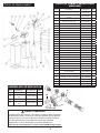
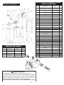
replaCemenT parTs:
ITEM
CODE DESCRIPTION
QTY
1.
C-254730B PROSOFT TOP COVER
1
2.
C-404008 PROSOFT TOP COVER TRIM
1
3.
C-254726 SALT TANK COVER
1
4. C-404040 PROSOFT KERAMIS CIRCUIT BOX 1
5. C-404043 PROTECTION SHIELD OF DISPLAY 1
6.
B-254362 F79BH-LCD VALVE DISPLAY
1
7. B-254345B
F79BH-LCD VALVE +7language with turbine
1
8.
C-254854DP 9x35 TOP VESSEL
1
9.
C-900001 C-100 STANDARD RESIN
26.46l
10.
B-254358 BRINE VALVE
1
11.
C-400005
CHIMNEY TOP COVER 1
12.
C-400004 CHIMNEY PIPE 82CM
1
13.
C-404014E ** PROSOFT INSTRUCTION MANUAL
1
14.
C-712014 1" TOP DISTRIBUTOR
1
15.
F-702108 1" BOTTOM DISTRIBUTOR
1
16.
C-254806 ELBOW TUBE 3/8" x TUBE 3/8"
1
17.
C-404056A PROSOFT FRONT DISPLAY STICKER
1
18.
C-322016 SOFT WHITE TUBE 3/8" DMT
0.352m
19.
C-404013C PROSOFT PACKAGE TOP COVER
1
20.
C-254485B 1/2ʼʼ food degree DRAIN TUBE
4m
21.
C-254600 SNAP RIVET 5x10
1
22.
C-254496 CENTER PVC PIPE 1" ø27 x 772
1
23.
C-254596 METALLIC CLAMP 20-22
1
24.
C-404034B PROSOFT PACKAGE BASE
1
25.
C-254728C PROSOFT BASE
1
26.
C-254485B Drain tube+metal clamp
2.2m
27.
C-254973A adapt for by-pass F70D
1
28.
B-400416E F70D by-pass without turbine
1
29.
C-254975 Clip by-pass
2
30.
C-713318 Flat joint
1
31.
C-254977 Injector (yellow)
1
32.
C-254491 Increaser
1
BYPASS ASSEMBLY
Item Description Model Qty.
28 Valve body zz.VWS296GR-28 1
34 Long Adapter Inlet ZZ.VWS296GR-34 1
35 H -Clip ZZ.VWS296GR-35 2
36 Short Adapter Inlet ZZ.VWS296GR-36 1
VWS296GR SOFTENER
CABINET PARTS
Item Description Part Number Qty.
1 Pro Soft Top Cover (Red) zz.VWS296GR-1 1
2
Pro Soft Top Cover Chrome
Bezel
zz.VWS296GR-2 1
3 Salt Tank Cover/Door zz.VWS296GR-3 1
4 Pro Soft Circuit Box zz.VWS296GR-4 1
5 Protection Shield of Display zz.VWS296GR-5 1
6 LCD Display zz.VWS296GR-6 1
7 Valve Assy zz.VWS296GR-7 1
8 FRP Tank zz.VWS296GR-8 1
9 Standard Resin (C-100) zz.VWS296GR-9 26.46L
10 Brine Valve zz.VWS296GR-10 1
11 Brine Tank Cover zz.VWS296GR-11 1
12 Brine Tank zz.VWS296GR-12 1
13 Pro Soft Instruction Manual zz.VWS296GR-13 1
14 1" Top Distributor Basket zz.VWS296GR-14 1
15 1" Bottom Distributor Basket zz.VWS296GR-15 1
16 Elbow Tube 3/8" x Tube 3/8" zz.VWS296GR-16 1
17 Pro Soft Front Display Sticker zz.VWS296GR-17 1
18 Soft White Tube 3/8" Dia. zz.VWS296GR-18 0.352m
19 Pro Soft Carton Box zz.VWS296GR-19 1
20 1/2" Drain Tube zz.VWS296GR-20 4m
21 Snap Rivet 5 x 10 zz.VWS296GR-21 1
22 Center PVC Pipe 1" x 772 zz.VWS296GR-22 1
23 Metallic Clamp 20-22 zz.VWS296GR-23 1
24 Pro Soft Carton Box Base zz.VWS296GR-24 1
25 Pro Soft Salt Cabinet (Grey) zz.VWS296GR-25 1
26 Drain Tune & Metal Clamp zz.VWS296GR-26 2.2m
27 Outlet Adapter & Flow Meter zz.VWS296GR-27 1
28 By-Pass Valve Assy zz.VWS296GR-28 1
29 Clip for By-Pass Valve zz.VWS296GR-29 2
30 Flat Joint zz.VWS296GR-30 1
31 Injector (Yellow) zz.VWS296GR-31 1
32 Increaser ( Spacer) zz.VWS296GR-32 1
28
35
34
36
WARNING
This Product can expose you to chemicals including Diisononyl
phthalate (DINP) which is known to the State of California to cause
cancer and Di-isodecyl phthalates (DIDP) which is known to the
State of California to cause birth defects or other reproductive harm.
For more information go to www.p65Warnings.ca.gov

Warranty
Retailer: Model Number:
Serial Number: Date Code:
Purchase Date:
DO NOT RETURN THIS PRODUCT TO THE STORE:
Please contact Customer Service at: 1-877-447-4768 or [email protected]
GHP Group Inc. warrants your water softener to be free from manufacturer’s defects in workmanship or material under normal operating
conditions for one (1) year from the original date of purchase. This warranty applies only in the country in which it is sold, and is available
to the original purchaser only. This warranty also covers for a period of ten (10) years, (parts only) from the original date of purchase, the
“Fiberglass Resin Tank” will not rust, corrode, leak or burst under normal operating conditions. This extended warranty does not cover the
cost of labour and/or freight associated with its replacement. This warranty is non-transferable.
This warranty is void if the water softener is altered, modified, or combined with any other machine or device. Alteration of this water
softener may cause serious flooding and/or hazardous electrical shock or fire.
The provisions of this warranty shall not apply to the following:
• Service performed by non-qualified service personnel.
• Service trips to your home to teach you how to use the product.
• Improper installation, delivery, or maintenance (failure to maintain the product according to the instructions outlined in the product
manual will automatically void the warranty).
• Failure of the product if it is abused, misused, altered, used commercially, or used for other than the intended purpose.
• Products that are used outside a residential or office environment.
• Replacement of house fuses or resetting of circuit breakers.
• Use of this product where water is microbiologically unsafe or of unknown quality.
• Damage to the product caused by accident, fire, floods, or acts of God.
• Any service to the product by unauthorized personnel.
• Incidental or consequential damage caused by possible defects with this appliance, its installation or repair.
This warranty shall be fulfilled only by an authorized GHP Repair Facility. All warranty repairs must be pre-authorized by GHP Group Inc.
GHP will, at its option, repair or replace free of charge any defective part, where the Purchaser has notified their Retailer or GHP Group
Inc. within the warranty period. The obligation of GHP Group Inc. under this warranty is expressly limited to such repairs or replacement.
This warranty does not cover the freight costs to and from the authorized repair facility
Except as set forth herein or required by law, the Manufacturer makes no other warranty, guarantee, or agreement, express, implied,
or statutory including any implied warranty of merchantability or fitness for a particular purpose. The manufacturer does not assume or
authorize any person to assume any obligations of liability in connection with this water softener. In no event will the manufacturer be
liable for indirect, special, or consequential damages (including, without limitation, economic loss) or for any delay in the performance of
this agreement due to causes beyond its control.
Some states or provinces do not allow limitations on how long an implied warranty lasts, so the above limitation may not apply to you.
Some states or provinces do not allow the exclusion or limitation of incidental or consequential damages, so the above limitation or
exclusion may not apply to you. This warranty gives you specific legal rights, and you may also have other rights which vary from state to
state or from province to province.
If you require service, please first see the “Troubleshooting” section of this manual. Additional assistance can be found by checking our
website at www.ghpgroupinc.com, or by calling our customer service line at 1-877-447-4768, Monday to Friday from 8:00 AM to 4:30
PM (CST), or write: GHP Group Inc., Customer Service Center, 271 Massey Road, Guelph, ON, Canada N1K 1B2 or GHP Group Inc.,
Customer Service Center, 6440 W. Howard Street, Niles, IL, USA 60714-3302.
Keep this manual and your sales slip together for future reference. You must provide proof of purchase for in-warranty service.
Write down the following information about your water softener to better help you obtain assistance or service if your ever need it. You will
need to know your complete model number and serial number. You can find this information on the back of the water softener.
Page is loading ...
Page is loading ...
Page is loading ...
Page is loading ...
Page is loading ...
Page is loading ...
Page is loading ...
Page is loading ...
Page is loading ...
Page is loading ...
Page is loading ...
Page is loading ...
Page is loading ...
Page is loading ...
Page is loading ...
Page is loading ...
Page is loading ...
Page is loading ...
Page is loading ...
Page is loading ...
Page is loading ...
Page is loading ...
Page is loading ...
Page is loading ...
Page is loading ...
Page is loading ...
Page is loading ...
Page is loading ...
Page is loading ...
Page is loading ...
Page is loading ...
Page is loading ...
Page is loading ...
Page is loading ...
Page is loading ...
Page is loading ...
-
 1
1
-
 2
2
-
 3
3
-
 4
4
-
 5
5
-
 6
6
-
 7
7
-
 8
8
-
 9
9
-
 10
10
-
 11
11
-
 12
12
-
 13
13
-
 14
14
-
 15
15
-
 16
16
-
 17
17
-
 18
18
-
 19
19
-
 20
20
-
 21
21
-
 22
22
-
 23
23
-
 24
24
-
 25
25
-
 26
26
-
 27
27
-
 28
28
-
 29
29
-
 30
30
-
 31
31
-
 32
32
-
 33
33
-
 34
34
-
 35
35
-
 36
36
-
 37
37
-
 38
38
-
 39
39
-
 40
40
-
 41
41
-
 42
42
-
 43
43
-
 44
44
-
 45
45
-
 46
46
-
 47
47
-
 48
48
-
 49
49
-
 50
50
-
 51
51
-
 52
52
-
 53
53
-
 54
54
-
 55
55


vitapur Pro Soft VWS296GR User manual
- Type
- User manual
- This manual is also suitable for
Ask a question and I''ll find the answer in the document
Finding information in a document is now easier with AI
in other languages
Related papers
Other documents
-
Kenmore Elite INTELLISOFT 420 SERIES 625.38426 User manual
-
Kenmore Elite Elite INTELLISOFT 420 SERIES 625.38426 Owner's manual
-
Tier1 TIER1-WH-HD-IRN-MG-1054 Installation guide
-
-
-
-
EcoWater ES9270R Owner's manual
-
Eco Pure NSC42 Specification
-
-