Baldor-Reliance RPM AC Direct Drive Type CTM Motor Cooling Tower Inverter Duty PM Motors (FL250, FL280, FL320, FL360, FL400, FL440 and FL580) Owner's manual
- Type
- Owner's manual

—
MN427 April 2020
April 2020
—
RPM AC Direct Drive Type CTM Motor
Inverter Duty PM Motors
(FL250, FL280, FL320, FL360, FL400, FL440 and FL580)
(Specifically designed for operation with
ACS880+N5350 Cooling Tower Drive)
Installation and Operating Manual

Any trademarks used in this manual are the property of their respective owners.
Note!: Be sure to check www.baldor.com to download the latest version of this manual in Adobe Acrobat PDF format.
Note! The manufacturer of these products, Baldor Electric Company, became ABB Motors and Mechanical Inc. on
March 1, 2018. Nameplates, Declaration of Conformity and other collateral material may contain the company name of
Baldor Electric Company and the brand names of Baldor-Dodge and Baldor-Reliance until such time as all materials
have been updated to reflect our new corporate identity.

iMN427
Section 1
General Information ................................................................. 1−1
Overview ....................................................................... 1−1
Safety Notice ................................................................... 1−1
Receiving ...................................................................... 1−2
Handling ....................................................................... 1−2
Storage ........................................................................ 1−2
Equipment Marking for IEC Product .................................................. 1−4
Section 2
Installation & Operation .............................................................. 2−1
Overview ....................................................................... 2−1
Mechanical Installation ............................................................ 2−1
Mounting Location ................................................................ 2−1
Alignment ...................................................................... 2−2
Guarding ....................................................................... 2−2
Electrical Installation .............................................................. 2−2
Thermostat Leads Connection ................................................... 2−2
Grounding .................................................................. 2−3
Conduit Box ..................................................................... 2−3
Condensation Drain ............................................................... 2−3
Fan Mounting ................................................................... 2−3
Bearing Axial Thrust Limits ......................................................... 2−4
Optional Accessories .............................................................. 2−5
First Time Start Up and Operation .................................................... 2−5
Air Flow Cooling ................................................................. 2−5
Maximum Safe Speed ......................................................... 2−5
Balance .................................................................... 2−5
Hazardous Locations ............................................................. 2−6
Selection .................................................................... 2−6
Section 3
Maintenance & Troubleshooting ....................................................... 3−1
General Inspection ................................................................ 3−1
Relubrication & Bearings .......................................................... 3−1
Lubrication Procedure ......................................................... 3−1
Interval and Type of Grease ..................................................... 3−2
Connection Box Maintenance ....................................................... 3−2
Troubleshooting Chart ............................................................. 3−3
Suggested bearing and winding RTD setting guidelines for Non−Hazardous Locations ONLY .... 3−3
Section 4
Information Required Per IEC 60079-0:2017 Ed7 .......................................... 4−1
Clause 30.1 (general) .............................................................. 4−1
Clause 30.3 (electrical machines ..................................................... 4−2
Table of Contents

ii MN427

1-1MN427
Section 1
General Information
Overview
This manual contains general procedures that apply to Baldor Motor products. Be sure to read and
understand the Safety Notice statements in this manual. For your protection, do not install, operate or
attempt to perform maintenance procedures until you understand the Warning and Caution statements.
A Warning statement indicates a possible unsafe condition that can cause harm to personnel.
A Caution statement indicates a condition that can cause damage to equipment.
Baldor mining motors are sold to OEM (Original Equipment Manufacturers) companies who provide
motors and equipment containing these motors as their product offerings. Be sure to consult the OEM
documents for safety and regulatory information that is important to the application of these products.
Important:
This instruction manual is not intended to include a comprehensive listing of all details for all
procedures required for installation, operation and maintenance. This manual describes general
guidelines that apply to most of the motor products shipped by Baldor. If you have a question
about a procedure or are uncertain about any detail, Do Not Proceed. Please contact your OEM
for more information or clarication.
Before you install, operate or perform maintenance, become familiar with the following:
• NEMA Publication MG-2, Safety Standard for Construction and guide for Selection, Installation and Use of
Electric Motors and Generators
• IEC 60034−1 Electrical and IEC60072−1 Mechanical specications
• NFPA 70
®
National Electrical Code (NEC) and local codes and practices.
Safety Notice:
This equipment contains high voltage! Electrical shock can cause serious or fatal injury.
Only qualied personnel should attempt installation, operation and maintenance of electrical equipment.
Be sure that you are completely familiar with MSHA (Mine Safety and Health Administration), safety
standards for selection, installation and use of electric motors and generators and local codes and
practices. Unsafe installation or use can cause conditions that lead to serious or fatal injury. Only
qualied personnel should attempt the installation, operation and maintenance of this equipment.
WARNING: Do not touch electrical connections before you first ensure that power has been disconnected. Electrical
shock can cause serious or fatal injury. Only qualified personnel should attempt the installation, operation
and maintenance of this equipment.
WARNING: Disconnect all electrical power from the motor windings and accessory devices before disassembling
of the motor. Electrical shock can cause serious or fatal injury.
WARNING: The Adjustable Speed Controller may apply hazardous voltages to the motor leads after power to the
controller has been turned off. Verify that the controller is incapable of delivering hazardous voltages and
that the voltage at the motor leads is zero before proceeding. Failure to observe this precaution may result
in severe bodily injury or death.
WARNING: Be sure the system is properly grounded before applying power. Do not apply AC power before you ensure
that all grounding instructions have been followed. Electrical shock can cause serious or fatal injury.
WARNING: Avoid extended exposure to machinery with high noise levels. Be sure to wear ear protective devices to
reduce harmful effects to your hearing.
WARNING: Surface temperatures of motor enclosures may reach temperatures which can cause discomfort or injury
to personnel accidentally coming into contact with hot surfaces. When installing, protection should be
provided by the user to protect against accidental contact with hot surfaces. Failure to observe this
precaution could result in bodily injury.
WARNING: Guards must be installed for rotating parts such as couplings, pulleys, external fans, and unused shaft
extensions, should be permanently guarded to prevent accidental contact by personnel.
Accidental contact with body parts or clothing can cause serious or fatal injury.
WARNING: This equipment may be connected to other machinery that has rotating parts or parts that are driven by
this equipment. Improper use can cause serious or fatal injury. Only qualified personnel should attempt to
install operate or maintain this equipment.
WARNING: Do not by-pass or disable protective devices or safety guards. Safety features are designed to prevent
damage to personnel or equipment. These devices can only provide protection if they remain operative.
WARNING: Be sure the load is properly coupled to the motor shaft before applying power. The shaft key must be
fully captive by the load device. Improper coupling can cause harm to personnel or equipment if the load
decouples from the shaft during operation.
WARNING: Use proper care and procedures that are safe during handling, lifting, installing, operating and maintaining
operations. Improper methods may cause muscle strain or other harm.
WARNING: Pacemaker danger − Magnetic and electromagnetic fields in the vicinity of current carrying conductors
and permanent magnet motors can result in a serious health hazard to persons with cardiac pacemakers,
metal implants, and hearing aids. To avoid risk, stay way from the area surrounding a permanent magnet
motor.
WARNING: Before performing any motor maintenance procedure, be sure that the equipment connected to the motor
shaft cannot cause shaft rotation. If the load can cause shaft rotation, disconnect the load from the motor
shaft before maintenance is performed. Unexpected mechanical rotation of the motor parts can cause
injury or motor damage.
WARNING: Mechanically lock or tie down the fan to prevent rotation as voltage will be produced even when the PM
motor is totally disconnected from the power source.
WARNING: Incorrect motor rotation direction can cause serious or fatal injury or equipment damage. Be sure to verify
motor rotation direction before coupling the load to the motor shaft.

1-2 MN427
Safety Notice Continued
WARNING: Motors that are to be used in flammable and/or explosive atmospheres must display the CSA listed logo.
Specific service conditions for these motors are defined in NFPA 70 (NEC) Article 500.
WARNING: Avoid the use of automatic reset devices if the automatic restarting of equipment can be hazardous to
personnel or equipment.
WARNING: RPM AC permanent magnet motors can induce voltage and current in the motor leads by rotating the
motor shaft. Electrical shock can cause serious or fatal injury. Therefore, do not couple the load to the
motor shaft until all motor connections have been made. During any maintenance inspections, be sure the
motor shaft will not rotate.
WARNING: Before performing any motor maintenance procedure, be sure that the equipment connected to the motor
shaft cannot cause shaft rotation. If the load can cause shaft rotation, disconnect the load from the motor
shaft before maintenance is performed. Unexpected mechanical rotation of the motor parts can cause
injury or motor damage.
WARNING: Do not use non UL/CSA listed explosion proof motors in the presence of flammable or combustible vapors
or dust. These motors are not designed for atmospheric conditions that require explosion proof operation.
WARNING: UL Listed motors must only be serviced by UL Approved Authorized Baldor Service Centers if these
motors are to be returned to a hazardous and/or explosive atmosphere.
Caution: Use only a shielded motor power cable with a complete circumferential braided or copper film/tape
ground jacket around the power leads. This ground should be secured to the motor frame from within the
motor terminal box and must return without interruption to the drive ground. In addition, if the motor and
coupled equipment are not on a single common metal base plate, it is important to equalize the equipment
ground potentials by bonding the motor frame to the coupled equipment using a high frequency conductor
such as a braided strap.
Caution: Do not lift the motor and its driven load by the motor lifting hardware. The motor lifting hardware is
adequate for lifting only the motor. Disconnect the load (gears, pumps, compressors, or other driven
equipment) from the motor shaft before lifting the motor.
Caution: Do not lift the motor by the shaft. The motor is designed to drive a load but it is not intended to have lifting
forces and stresses applied to the motor shaft. Damage to the motor may result.
Caution: If eye bolts are used for lifting a motor, be sure they are securely tightened. The lifting direction should not
exceed a 20° angle from the shank of the eye bolt or lifting lug. Excessive lifting angles can cause damage.
Caution: To prevent equipment damage, be sure that the electrical service is not capable of delivering more than
the maximum motor rated amps listed on the rating plate.
Caution: If a HI POT test (High Potential Insulation test) must be performed, follow the precautions and procedure in
NEMA MG1 and MG2 standards to avoid equipment damage.
Caution: Do not use an induction oven to heat noise tested bearings. Arcing between the balls and races may
damage the bearing. Failure to observe this precaution may result in equipment damage.
If you have any questions or are uncertain about any statement or procedure, or if you require additional
information please contact your Baldor District ofce or an Authorized Baldor Service Center.
Receiving Each Baldor Electric Motor is thoroughly tested at the factory and carefully packaged for shipment.
When you receive your motor, there are several things you should do immediately.
1. Observe the condition of the shipping container and report any damage immediately to the commercial
carrier that delivered your motor.
2. Verify that the part number of the motor you received is the same as the part number listed on your purchase
order.
Handling The motor should be lifted using the lifting lugs or eye bolts provided.
1. Use the lugs or eye bolts provided to lift the motor. Never attempt to lift the motor and additional equipment
connected to the motor by this method. The lugs or eye bolts provided are designed to lift only the motor.
Never lift the motor by the motor shaft or the hood of a WPII motor. If eye bolts are used for lifting a motor, be
sure they are securely tightened. The lifting direction should not exceed a 20° angle from the shank of the eye
bolt. Excessive lifting angles can cause motor damage.
2. To avoid condensation inside the motor, do not unpack until the motor has reached room temperature. (Room
temperature is the temperature of the room in which it will be installed). The packing provides insulation from
temperature changes during transportation.
Storage Storage requirements for motors and generators that will not be placed in service for at least six months
from date of shipment. Improper motor storage will result in seriously reduced reliability and failure. An electric
motor that does not experience regular usage while being exposed to normally humid atmospheric conditions is
likely to develop rust in the bearings or rust particles from surrounding surfaces may contaminate the bearings.
The electrical insulation may absorb an excessive amount of moisture leading to the motor winding
failure.
A wooden crate “shell” should be constructed to secure the motor during storage. This is similar to an
export box but the sides & top must be secured to the wooden base with lag bolts (not nailed as export
boxes are) to allow opening and closing many times without damage to the “shell”.
Minimum resistance of motor winding insulation is 5 Meg ohms or the calculated minimum, which ever
is greater. Minimum resistance is calculated as follows: Rm = kV + 1
where: (Rm is minimum resistance to ground in Meg- Ohms and
kV is rated nameplate voltage dened as Kilo- Volts.)
Example: For a 480VAC rated motor Rm =1.48 meg- ohms (use 5 MΩ).
For a 4160VAC rated motor Rm = 5.16 meg- ohms.

1-3MN427
Preparation for Storage
1. Some motors have a shipping brace attached to the shaft to prevent damage during transportation. The
shipping brace, if provided, must be removed and stored for future use. The brace must be reinstalled to
hold the shaft rmly in place against the bearing before the motor is moved.
2. Store in a clean, dry, protected warehouse where control is maintained as follows:
a. Shock or vibration must not exceed 2 mils maximum at 60 hertz, to prevent the bearings from brinelling.
If shock or vibration exceeds this limit vibration isolation pads must be used.
b. Storage temperatures of 10 °C (50 °F) to 49 °C (120 °F) must be maintained.
c. Relative humidity must not exceed 60%.
d. Motor space heaters (when present) are to be connected and energized whenever there is a possibility
that the storage ambient conditions will reach the dew point. Space heaters are optional.
Note: Remove motor from containers when heaters are energized, reprotect if necessary.
3. Measure and record the resistance of the winding insulation (dielectric withstand) every 30 days of storage.
a. If motor insulation resistance decreases below the minimum resistance, contact your OEM.
b. Place new desiccant inside the vapor bag and re−seal by taping it closed.
c. If a zipper−closing type bag is used instead of the heat−sealed type bag, zip the bag closed instead of
taping it. Be sure to place new desiccant inside bag after each monthly inspection.
d. Place the shell over the motor and secure with lag bolts.
4. Where motors are mounted to machinery, the mounting must be such that the drains and breathers are fully
operable and are at the lowest point of the motor. Vertical motors must be stored in the vertical position.
Storage environment must be maintained as stated in step 2.
5. Motors with anti−friction bearings are to be greased at the time of going into extended storage with periodic
service as follows:
a. Motors marked “Do Not Lubricate” on the nameplate do not need to be greased before or during
storage.
b. Ball and roller bearing (anti−friction) motor shafts are to be rotated manually every 3 months and greased
every 6 months in accordance with the Maintenance section of this manual.
6. All breather drains are to be fully operable while in storage (drain plugs removed). The motors must be stored
so that the drain is at the lowest point. All breathers and automatic “T” drains must be operable to allow
breathing and draining at points other than through the bearings around the shaft.
Vertical motors should be stored in a safe stable vertical position.
7. Coat all external machined surfaces with a rust preventing material. An acceptable product for this purpose
is Exxon Rust Ban # 392.
Non−Regreaseable Motors
Non−regreaseable motors with “Do Not Lubricate” on the nameplate should have the motor shaft rotated 15
times to redistribute the grease within the bearing every 3 months or more often.
All Other Motor Types
Before storage, the following procedure must be performed.
1. Remove the grease drain plug, if supplied, (opposite the grease tting) on the bottom of each bracket prior to
lubricating the motor.
2. The motor with regreaseable bearing must be greased as instructed in Section 3 of this manual.
3. Replace the grease drain plug after greasing.
4. The motor shaft must be rotated a minimum of 15 times after greasing.
5. Motor Shafts are to be rotated at least 15 revolutions manually every 3 months and additional grease added
every nine months (see Section 3) to each bearing.
6. Bearings are to be greased at the time of removal from storage.
Removal From Storage
1. Remove all packing material.
2. Measure and record the electrical resistance of the winding insulation resistance meter at the time of removal
from storage. The insulation resistance must not be less than 50% from the initial reading recorded when the
motor was placed into storage. A decrease in resistance indicates moisture in the windings and necessitates
electrical or mechanical drying before the motor can be placed into service. If resistance is low, contact your
OEM.
3. Regrease the bearings as instructed in Section 3 of this manual.
4. Reinstall the original shipping brace if motor is to be moved. This will hold the shaft rmly against the bearing
and prevent damage during movement.

1-4 MN427
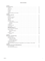
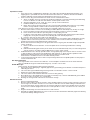
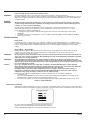
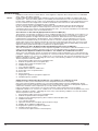
Equipment Marking for IEC Certified Product
IEC certied products have special markings that identify the protection concept and environment requirements.
An example is shown in Figure 1-1.
Figure 1-1 IEC Certified Product Markings
Specific Conditions of Use:
If the motor certicate number is followed by the symbol “X”, this indicates that the motor has specic conditions
of use which are indicated on the certicate. It is necessary to review the product certication certicate in
conjunction with this instruction manual.
Operation On Frequency Converters:
If the motor is evaluated for operation with an adjustable speed drive, the type of converter (for example PWM
for Pulse Width Modulated) and safe speed ranges (for example 0- 120Hz) will be specied in the certication
documents or on motor nameplates. It is necessary to consult the adjustable speed drive manual for proper set
up. IECEx Certicates are available online at www.iecex.com
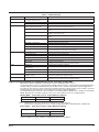
Unit Conversions
Inches to Millimeters Inches x 25.4 = mm
Millimeters to Inches mm x .03937 = Inches
Horsepower to Kilowatts Hp x .746 = Kw
Kilowatts to Horsepower Kw x 1.341 = Hp
Pounds to Kilograms Lbs x .454 = Kg
Kilograms to Pounds Kg x 2.205 = Lbs
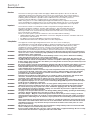
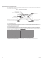
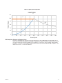
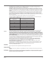
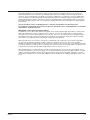
Typical Speed versus Torque Curves are shown in Figure 1-2. For values relative to your specic motor,
consult the motor nameplate marking.
Ex ec MOTOR
MFG. BY BALDOR ELECTRICFORTSMITH,AR72901 USA
Ex ec IICGcTamb ºCto ºC
II 3G IP______
Sira__________________
IECEx__________________
Ex Protection Concept(Ex ec)
GasGroup (IIC)
Temperature Class
ATEX Specic
Markingof
ExplosionProtection
A
TEXEquipment Group and Category (II3)
Type of Atmosphere: G--Gas,D-- Dust(G)
AmbientRange
European ConformityMar
k
PlaceofManufacture

1-5MN427
Figure 1-2 Typical Speed vs Torque Curves
0
20
40
60
80
100
120
0 20 40 60 80 100 120 140 160 180 200
Percent Torque
Percent Speed
Load Types
VT
CT
CHP
EMC Compliance Statement for European Union
The motors described in this instruction manual are designed to comply 2004/108/EC and 2014/30/EU. These
motors are commercial in design and not intended for residential use. When used with converters, please consult
converter manufacturers literature regarding recommendations on cable types, cable shielding, cable shielding
termination, connection recommendations and any lters which may be recommended for EMC compliance. For
additional information, consult Baldor MN1383.

1-6 MN427

2-1MN427
Section 2
Installation & Operation
Overview Installation should conform to the National Electrical Code as well as local codes and practices. When other
devices are coupled to the motor shaft, be sure to install protective devices to prevent future accidents. Some
protective devices include, coupling, belt guard, chain guard, shaft covers etc. These protect against accidental
contact with moving parts. Machinery that is accessible to personnel should provide further protection in the form
of guard rails, screening, warning signs etc.
RPM AC Cooling Tower PM motors are high performance motors specically designed for use with adjustable
frequency controllers. The basic design includes Class H insulation, 1.0 service factor, 40°C ambient, continuous
duty. Standard enclosure is totally enclosed air over (TEAO) with minimum recommended air ow velocities
provided by the application fan. Many modications, and accessories are available. Motors are permanent
magnet rotor construction. Refer to the motor nameplate or the performance data sheet for the rated air velocity.
Motors are designed exclusively for outdoor cooling tower environments. Rated air ow is required for proper
operation. Motors are designed to mount inside the cooling tower with the fan mounted directly to the motor shaft.
Mechanical Installation
Caution: Do not lift the motor and its driven load by the motor lifting hardware. The motor lifting hardware is
adequate for lifting only the motor. Disconnect the fan from the motor shaft before lifting the motor.
Caution: Do not lift the motor by the shaft. The motor is designed to drive a load but it is not intended to have lifting
forces and stresses applied to the motor shaft. Damage to the motor may result.
Caution: If eye bolts are used for lifting a motor, be sure they are securely tightened. The lifting direction should not
exceed a 20° angle from the shank of the eye bolt or lifting lug. Excessive lifting angles can cause damage.
After storage or after unpacking and inspection to see that all parts are in good condition, do the following:
i. Rotate the motor shaft by hand to be sure there are no obstructions to free rotation.
ii. A motor that has been in storage for some time should be tested for moisture (dielectric withstand insulation
test) and relubricated (regreasable type) prior to being put into service.
iii. A motor with roller bearings is shipped with a shaft block. After removing the shaft block, be sure to replace
any bolts used to hold the shaft block in place during shipment that are required in service.
Table 2-1 Tightening Torque
NEMA Frame Hole Dia. (Inch) Bolt Size
& Thread
Torque lb−ft for Bolt Grade
SAE 5 SAE 8
FL250Y 0.69 5/8-11 155-176 200-249
FL280Y 0.69 5/8-11 155-176 200-249
FL320Y 0.81 3/4-10 274-310 389-440
FL360Y 0.81 3/4-10 274-310 389-440
FL400Y 0.81 3/4-10 274-310 389-440
FL440Y 0.81 3/4-10 274-310 389-440
FL5800Y 1.06 7/8-9 434-486 616-689
Mounting Location
All RPM AC Direct Drive CTM Motors may be mounted vertical, shaft up, supported by the opposite drive end
bracket. Use appropriate hardware (not furnished). The motor should be installed in a location compatible with
the motor enclosure required air ow and specic ambient.
The motor must be securely installed to a rigid foundation or mounting surface to minimize vibration and maintain
alignment between the motor and fan blades within the cooling tower walls. Failure to provide a proper mounting
surface may cause vibration, misalignment and bearing damage. All hold down bolts must be the correct grade
for the type of mounting and must be torqued to their recommended value.
Foundation caps and sole plates are designed to act as spacers for the equipment they support. If these devices
are used, be sure that they are evenly supported by the foundation or mounting surface.
When installation is complete and accurate alignment of the motor and fan is accomplished, the base should be
grouted to the foundation to maintain this alignment.
The standard motor base is designed for vertical mounting.
Installation Procedure:
i. Verify that the motor shaft is compatible with fan hub design and that the planned mounting surface is
compatible with the opposite drive end ange mounting hole conguration.
ii. Verify that the fan is properly balanced prior to lowering down onto the motor shaft.
iii. Follow all safety lock out and tag out procedures for conned space installation.
iv. Ensure that the Direct Drive CTM Motor mounting surface is at and mechanically suitable for the Direct
Drive CTM Motor ange mounting.
v. Lower the motor in place using the four motor eye bolts.
vi. Level the motor with respect to the base. Use a dial indicator on top of the motor feet and verify that foot
deection does not exceed 0.005 in (0.125 mm) as the mounting bolts are tightened.
vii. Shims should be used under motor feet to prevent excessive deection that causes permanent deformation
of the motor feet.
viii. Secure the motor to the cooling tower structure with ange mounting bolts, not provided.
Installation Procedure: Continued
ix. Tighten the ange mounting bolts to the proper torque specication.
x. Lower and mount the fan hub directly onto the motor shaft making sure that the proper blade tip clearance
and proper fan blade height is maintained for the specic tower requirements.
Make sure the fan is tightened securely to prevent parts from ying off during fan rotation.

2-2 MN427
WARNING: Mechanically lock or tie down the fan to prevent rotation as voltage will be produced even when the PM
motor is totally disconnected from the power source.
Alignment Accurate alignment of the motor within the cooling tower structure is extremely important.
Mechanical vibration and roughness during operation may indicate poor alignment. Use dial indicators to check
alignment. The space between fan hub and motor should be checked and maintained as recommended by the
fan manufacturer.
Guarding
WARNING: Guards must be installed for rotating parts such external fans, and unused shaft extensions, should be
permanently guarded to prevent accidental contact by personnel. Accidental contact with body parts or
clothing can cause serious or fatal injury.
Guards must be installed for rotating parts such as external fans, and unused shaft extensions. This is
particularly important where the parts have surface irregularities such as keys, key ways or set screws.
Some satisfactory methods of guarding are:
i. Covering the machine and associated rotating parts with structural or decorative parts of the driven
equipment.
ii. Providing covers for the rotating parts. Covers should be sufciently rigid to maintain adequate guarding
during normal service.
Electrical Installation
Flying Leads
For ExnA hazardous location motors, it is a specic condition of use that all terminations in a conduit box be
fully insulated. Fully insulated and lugged terminations must be bolted and provided with lock washer to prevent
rotation. Flying leads must be insulated with two full wraps of electrical grade insulating tape or heat shrink
tubing.
Bypass Mode − Not Available
All RPM AC Direct Drive CTM Motors are inverter duty motors using optimum pole design with permanent
magnet rotor construction. They are not intended to be used in bypass mode (across the line). These
motors cannot be run in bypass mode.
WARNING: Do not touch electrical connections before you first ensure that power has been disconnected. Electrical
shock can cause serious or fatal injury. Only qualified personnel should attempt the installation, operation
and maintenance of this equipment.
WARNING: The Adjustable Speed Controller may apply hazardous voltages to the motor leads after power to the
controller has been turned off. Verify that the controller is incapable of delivering hazardous voltages and
that the voltage at the motor leads is zero before proceeding. Failure to observe this precaution may result
in severe bodily injury or death.
Caution: Use only a shielded motor power cable with a complete circumferential braided or copper film/tape
ground jacket around the power leads. This ground should be secured to the motor frame from within the
motor terminal box and must return without interruption to the drive ground.
In addition, if the motor and coupled equipment are not on a single common metal base plate, it is
important to equalize the equipment ground potentials by bonding the motor frame to the coupled
equipment using a high frequency conductor such as a braided strap.
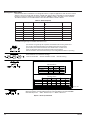
Note: Main power leads for CE Marked Motors may be marked U,V,W – for standard congurations
(see Figure 2-1).
i. Refer to manual MN799UG. Connect all motor leads, thermostat leads and vibration switch leads to the
ACS880+5350 Cooling Tower Drive as described in Chapters 5 & 6.
ii. Be sure all connections are secure and proper tightening torque values (MN799UG, Chapter 4) are used.
Figure 2-1 Connection Diagram
Thermostat Leads Connection
RPM AC Direct Drive CTM Motors may three (3) normally closed thermostats (one per phase) connected in series,
with leads P1 and P2 terminated in the main conduit box. To protect against motor overheating, thermostats must
be connected to the appropriate controller circuit (function loss).
Failure to connect the thermostats will void the motor warranty.
Refer to MN799UG Chapter 6 for correct thermostat lead connections.
3 Phase Single Voltage
P1
P2
U/T1
V/T2
W/T3
T'Stat
L1
L2
L3

2-3MN427
Grounding In Europe, the customer is responsible to ensure ground method conforms to IEC and applicable local codes.
Grounding provisions are inside the motor conduit box for European CE compliance and a ground hole is
provided in the opposite drive end bracket as standard features.
In the USA consult the National Electrical Code (NEC), Article 430 for information on grounding of motors and
generators, and Article 250 for general information on grounding. In making the ground connection, the installer
should make certain that there is a solid and permanent metallic connection between the ground point, the motor
terminal housing, and the motor frame. A ground hole is provided in the opposite drive end bracket as standard
features.
There are applications where grounding the exterior parts of a motor may result in greater hazard by increasing
the possibility of a person in the area simultaneously contacting ground and some other nearby live electrical
parts of other ungrounded electrical equipment. In portable equipment it is difcult to be sure that a positive
ground connection is maintained as the equipment is moved, and providing a grounding conductor may lead to a
false sense of security.
Select an ACS880+5350 Cooling Tower Drive suitable for this motor and its application.
For motors installed in compliance with IEC requirements, the following minimum cross sectional area of the
protective conductors should be used:
Cross sectional area of phase
conductors, S
Minimum cross sectional area of the
corresponding protective conductor, S
p
mm2 mm2
6 6
10 10
16 16
25 25
35 25
50 25
70 35
95 50
120 70
150 70
Equipotential bonding connection shall made using a conductor with a cross-sectional area of at least 4 mm
2
.
Caution: Use only a shielded motor power cable with a complete circumferential braided or copper film/tape
ground jacket around the power leads. This ground should be secured to the motor frame from within the
motor terminal box and must return without interruption to the drive ground. In addition, if the motor and
coupled equipment are not on a single common metal base plate, it is important to equalize the equipment
ground potentials by bonding the motor frame to the coupled equipment using a high frequency conductor
such as a braided strap.
Due to the high switching frequencies of inverter controls, the ground connection/path must be low impedance,
not only low resistance. The NEC grounding instructions are intended to protect from low frequency, high current
considerations and are not adequate for grounding of high frequency circuits.
RPM AC cooling tower PM motors are designed to operate with the ACS880+5350 Cooling Tower Drive.
To avoid damage to the motor due to bearing currents, the motor must be grounded and bonded properly.
A low impedance ground conductor should be used to ground all RPM AC motors.
Failure to ground the motor properly for high frequency transients (1MHz to 10MHz) may result in electric
discharge damage to the motor bearings.
For the motor power a shielded motor power cable that includes a complete circumferential braided or copper
lm/tape ground is recommended. This ground should be secured to the motor frame from within the motor
terminal box and must return without interruption to the drive PE ground connection.
Refer to manual MN799UG Chapter 5.
Conduit Box
All Incoming Leads must be supplied with a Water Tight Lead Connection.
Condensation Drain
All RPM AC Direct Drive CTM Motors are provided with a stainless steel Drain at the lowest point of the bottom
bracket.
Fan Mounting RPM AC Direct Drive CTM Motors are supplied with a shaft suitable for mounting the fan hub directly to the motor
shaft. The motor must be ordered with the appropriate shaft dimensions to match the fan hub. Fan should be
balanced to ISO G6.3 Balance Grade or Better.

2-4 MN427
Bearing Axial Thrust Limits
RPM AC Direct Drive CTM Motors are designed for direct couple fan applications with the fan mounted
directly to the motor shaft. Both the drive end (DE) and opposite drive end (ODE) use regreasable ball
bearing construction. Bearings are sized for minimum 100,000 L−10 life. See Table 2−2 for maximum
allowable load limits. Fan should be balanced to ISO G6.3 Balance Grade or Better.
Table 2-2 Axial Load Capacity
Frame DE Bearing Size ODE Bearing Size ODE Axial Thrust Max Lbs @ XXX
RPM
RPM
FL250Y 6211 6313 470 500
FL280Y 6313 6314 675 300
FL320Y 6313 6316 1400 300
FL360Y 6316 6222 1420 300
FL400Y 6222 6222 1080 300
FL440Y 6222 6322 1525 275
FL5800Y 6228 Tandem Set 7228 9500 125
* FL5800 bearing design can handle down thrust only.
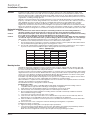
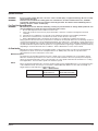
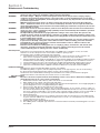
Space heaters are generally not required as the ACS880+5350 Cooling Tower Drive
has a trickle current heating feature. For extreme applications that require
space heaters, one heater is installed in each end of motor. Leads for each
heater are labeled H1 & H2. (Like numbers should be tied together).
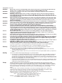
Three thermistors are installed in windings.
Leads are labeled TD1 −TD6 for shutdown and TD7 −TD12 for warning.
* One bearing RTD is installed in Drive end plate (PUEP), leads are labeled RTDDE.
* One bearing RTD is installed in Opposite Drive end plate (FREP), leads labeled RTDODE.
* Note RTD may have 2 −Red/1 −White leads; or 2 −White/1−Red Lead.
RTD CONNECTIONS
1TD1
1TD2
1TD3
418057 −549
Phase1 Phase2 Phase3
One Per Phase
Two Per Phase
Phase1 Phase2 Phase3
#1
#2 #3
#4
#5 #6
Red
White
White
Leads
(or Marked)
Red
White
White
Leads
(or Marked)
2TD1
2TD2
2TD3
3TD1
3TD2
3TD3
1TD1
1TD2
1TD3
2TD1
2TD2
2TD3
3TD1
3TD2
3TD3
4TD1
4TD2
4TD3
5TD1
5TD2
5TD3
6TD1
6TD2
6TD3
Heaters should be connected such that they are not energized when motor is operating
Figure 2-2 Accessory Connections

2-5MN427
Optional Accessories
WARNING: Incorrect motor rotation direction can cause serious or fatal injury or equipment damage. Be sure to verify
motor rotation direction.
WARNING: Guards must be installed for rotating parts such external fans, and unused shaft extensions, should be
permanently guarded to prevent accidental contact by personnel. Accidental contact with body parts or
clothing can cause serious or fatal injury.
First Time Start Up and Operation
WARNING: Mechanically lock or tie down the fan during servicing to prevent rotation as voltage will be produced even
when the PM motor is totally disconnected from the power source.
i. Be sure that all power to motor and accessories is off.
ii. Inspect all electrical connections for proper termination, clearance, mechanical strength and electrical
continuity.
iii. Install the motor conduit box cover and all covers and panels that were removed during installation.
iv. Remove the mechanical lock or tie down from the fan to allow the fan to turn freely.
v. Refer to MN799UG Chapter 7 and follow the procedures to complete the installation and start up.
During operation observe the motors’ performance. It should run smoothly with little noise. The bearings should not
overheat and should reach a normal operating temperature. Any undue noise, overheating, or erratic performance
should be investigated and corrective action taken immediately to prevent serious damage. All RPM AC motors
are lubricated before shipment and will operate for a long period before regreasing is required. The period will vary
depending on environmental and service conditions. Refer to Maintenance section of this manual.
Air Flow Cooling
RPM AC Direct Drive CTM Motors are rated based upon cooling tower air ow over the motor and ambient air
temperature as shown on the motor nameplate. Motors are TEAO (totally enclosed air over) with air ow
generated from the fan mounted to the motor shaft.
Maximum Safe Speed
The maximum safe operating speed of the motor is listed on the motor nameplate. Do not exceed this speed.
When the maximum speed of the motor control can exceed the maximum safe motor speed (motor nameplate
value), the speed characteristics of the control must be set so the speed is limited to this maximum. For cooling
tower applications, the motor base speed is the maximum speed.
Balance
Motors are dynamically balanced to meet the dynamic balance limits of NEMA MG1 Part 7 second for peak value
of the unltered velocity in inches per second unless ordered differently. Balance is done with a full length 1/2
height shaft key. A full shaft key is shipped with motor.
Table 2-3 Dynamic Balance
RPM NEMA
Velocity Peak (in/sec)
IEC
Velocity Peak (mm/sec RMS)
0-600 0.15 2.7

2-6 MN427
Hazardous Locations
Hazardous locations are those where there is a risk of ignition or explosion due to the presence of combustible
gases, vapors, dust, bers or yings.
Selection Facilities requiring special equipment for hazardous locations are typically classied in accordance with local
requirements. In the US market, guidance is provided by the National Electric Code. In international hazardous
location areas, guidance for gas / vapor / mist classication is given in IEC60079−14. This classication process
lets the installer know what equipment is suitable for installation in that environment, and identies what the
maximum safe temperature or temperature class is required.
It is the customer or users responsibility to determine the area classication and select proper equipment.
Areas are classied with respect to risk and exposure to the hazard. In the US market, areas are typically
classied as follows Class, Division, Group and Temperature Class. In some newer installations in the US and in
most international markets, areas are classied in Zones.
Class I Division 2 / Zone 2 Ex nA, [Equipment Protection Level (EPL) Gc ]
This protection concept relies on having no sources of ignition present such as arcing parts or hot surfaces. For
this protection concept, internal temperatures as well as external temperatures are considered. In many cases,
the internal temperatures are higher than the external temperatures and therefore become the limiting factor
in determination of temperature code designation. In these applications, it is very important to use a motor
that has been evaluated thermally for use with an inverter or converter, if variable speed operation is desired.
Thermostats used for Class I Division 2 and Ex nA motors are used to protect the motor only. For motors using
ying lead construction, it is important to use connection lugs and insulate with heat shrink tubing or a double
wrap of insulation grade electrical tape to avoid the risk of spark or ignition.
Class II Division 2 / Zone 22 [Equipment Group III, Equipment Protection Level (EPL) Dc ]
This area classication is one where the risk of exposure to ignitable concentrations of dust are not likely to occur
under normal operating conditions and relies heavily on the housekeeping practices within the installation.
Sine Wave Power Operation for Division 2 and Zone 1 or 2 and Zone 21 or 22 Hazardous Location.
These motors are designed to operate at or below the maximum surface temperature (or T−Code) stated on the
nameplate. Failure to operate the motor properly can cause this maximum surface temperature to be exceeded.
If applied in a Division 1 or 2 / Zone 1 or 2 and Zone 21 or 22 environment, this excessive temperature may cause
ignition of hazardous materials. Operating the motor at any of the following conditions can cause the marked
surface temperature to be exceeded.
i. Motor load exceeding service factor nameplate value
ii. Ambient temperatures above nameplate value
iii. Voltages above or below nameplate value
iv. Unbalanced voltages
v. Loss of proper ventilation
vi. Altitude above 3300 feet / 1000 meters
vii. Severe duty cycles of repeated starts
viii. Motor stall
ix. Motor reversing
x. Single phase operation of polyphase equipment
xi. Variable frequency operation
Variable Frequency Power Operation for Division 1 or 2 and Zone 1 or 2 and Zone 21 or 22
Hazardous Location (motors with maximum surface temperature listed on the nameplate).
Only motors with nameplates marked for use on inverter (variable frequency) power, and labeled for specic
hazardous areas may be used in those hazardous areas on inverter power. The motor is designed to operate at
or below the maximum surface temperature (or T−Code) stated on the nameplate.
Failure to operate the motor properly can cause this maximum surface temperature to be exceeded.
If applied in a Division 1 or 2 / Zone 1 or 2 and Zone 21 or 22 environment, this excessive temperature may cause
ignition of hazardous materials. Operating the motor at any of the following conditions can cause the marked
surface temperature to be exceeded.
i. Motor load exceeding service factor nameplate value
ii. Ambient temperature above nameplate value
iii. Voltage (at each operating frequency) above or below rated nameplate value
iv. Unbalanced voltages
v. Loss of proper ventilation
vi. Operation outside of the nameplate speed / frequency range
vii. Altitudes above 3300 feet / 1000 meters
viii. Single phase operation of polyphase equipment
ix. Unstable current wave forms
x. Lower than name plate minimum carrier frequency

2-7MN427
Thermal Limiting
Thermal limiting devices are temperature sensing control components installed inside the motor to limit the
internal temperature of the motor frame by interrupting the circuit of the holding coil of the magnetic switch or
contactor. They are required for most Division 1 and Zone 1 applications. For Division 2 or Zone 2 applications,
motors should be selected that preclude running temperatures from exceeding the ignition temperatures for the
designated hazardous material. In Division 2 or Zone 2 classied locations, thermal limiting devices should only
be used for winding protection and not considered for limiting all internal motor temperatures to specic ignition
temperatures.
Specific Conditions of Use” for Ex Equipment or “Schedule of Limitations” for Ex Components:
See Certificate supplied with the motor for the Specific “Conditions of Use” for Ex Equipment or “Schedule
of Limitations” for Ex Components.
RPM-AC Direct Drive Permanent Magnet Motors
The RPM-AC series of direct drive permanent magnet motors are designed for high power dense, slower speed
high torque applications such as cooling tower fan or mixers, etc. The can only be used in conjunction with a
converter. They cannot be operated directly across the line. The motors are optimized for the nameplate rating.
The optimum Volts and Current are provided on the nameplate for the optimum rating. When optimum voltage
and current is not supplied to the motor optimum rating may not be obtained.
When sizing the motor for use with a converter the voltage drop of all components such as lters, long cables,
etc. may prevent optimum operating conditions and have to be taken into account. The motor nameplate
identies the optimum voltage into the motor and a set up voltage for the converter. This set up voltage should be
used when operation in scalar mode. The nameplate also shows the open circuit voltage which may also be used
if required by the inverter. The allowable voltage variation for these motors is +/- 5 %.
When programing the converter and motor system the motor parameters such as; motor set up voltage, motor
current, motor frequency, open circuit voltage, etc. should be taken from the motor nameplates and the converter
output current limit should be set at the motor full load current shown on the nameplate. Setting the converter
current limit should prevent a converter with additional current capability from supplying damaging current to the
motor.

2-8 MN427

3-1MN427
Section 3
Maintenance & Troubleshooting
WARNING: UL Listed motors must only be serviced by UL Approved Authorized Baldor Service Centers if these
motors are to be returned to a hazardous and/or explosive atmosphere.
WARNING: Pacemaker danger − Magnetic and electromagnetic fields in the vicinity of current carrying carrying
conductors and permanent magnet motors can result result in a serious health hazard to persons with
cardiac pacemakers, metal implants, and hearing aids. To avoid risk, stay way from the area surrounding a
permanent magnet motor.
WARNING: RPM AC permanent magnet motors can induce voltage and current in the motor leads by rotating the
motor shaft. Electrical shock can cause serious or fatal injury. Therefore, do not couple the load to the
motor shaft until all motor connections have been made. During any maintenance inspections, be sure the
motor shaft will not rotate.
WARNING: Do not touch electrical connections before you first ensure that power has been disconnected. Electrical
shock can cause serious or fatal injury. Only qualified personnel should attempt the installation, operation
and maintenance of this equipment.
WARNING: The Adjustable Speed Controller may apply hazardous voltages to the motor leads after power to the
controller has been turned off. Verify that the controller is incapable of delivering hazardous voltages and
that the voltage at the motor leads is zero before proceeding. Failure to observe this precaution may result
in severe bodily injury or death.
WARNING: Surface temperatures of motor enclosures may reach temperatures which can cause discomfort or injury
to personnel accidentally coming into contact with hot surfaces. When installing, protection should be
provided by the user to protect against accidental contact with hot surfaces. Failure to observe this
precaution could result in bodily injury.
WARNING: Guards must be installed for rotating parts such as couplings, pulleys, external fans, and unused shaft
extensions, should be permanently guarded to prevent accidental contact by personnel. Accidental
contact with body parts or clothing can cause serious or fatal injury.
General Inspection
Inspect the motor at regular intervals, approximately every 8000 hours of operation or every 12 months,
whichever occurs rst. Keep the motor clean and the ventilation openings clear.
The following steps should be performed at each inspection:
1. Check that the motor is clean. Check that the exterior ns of the motor are free of dirt, oil, grease, etc.
If the motor is not properly ventilated, overheating can occur and cause early motor failure.
2. Perform a dielectric with stand test periodically to ensure that the integrity of the winding insulation has been
maintained. Record the readings. Immediately investigate any signicant decrease in insulation resistance.
3. Check all electrical connectors to be sure that they are tight and supplied with a Water Tight Connector.
4. Check the Conduit Box and Cover to ensure all Bolts and Connections are Tight and properly Sealed.
5. Inspect the Condensation Drains supplied on the bottom bracket to ensure they are free of debris.
Relubrication & Bearings
Bearing grease will lose its lubricating ability over time, not suddenly.
The lubricating ability of a grease (over time) depends primarily on the type of grease, the size of the bearing,
the speed at which the bearing operates and the severity of the operating conditions.
Good results can be obtained if the following recommendations are used in your maintenance program.
Relubrication with the shaft stationary and a warm motor is recommended.
Lubrication Procedure
WARNING: Disconnect all electrical power from the motor windings and accessory devices before disassembly of the
motor. Electrical shock can cause serious or fatal injury.
1. Relubrication with the shaft stationary and a warm motor is recommended.
2. Wipe all dirt from the outside of the grease lls and drains.
3. Locate the grease inlet at the top of the bearing hub, clean the area and replace the 1/8−inch pipe plug with a
grease tting if the motor is not equipped with grease tting.
4. Remove grease drain plug located opposite the grease inlet.
5. Using a manual grease gun, pump in the recommended grease in the amount shown in Table 3-1.
This amount will provide an ample supply of lubricant between lubrication intervals. Use only clean, fresh grease
from clean containers and handle so as to keep it clean. In general, mixing of greases is not recommended. If
an incompatible grease is used, the lube system must be repacked completely with the new grease.
6. Replace drain plugs.
7. It is not uncommon that grease may not appear at the grease drain even though the recommended amount
of grease has been added. This condition should not cause concern. It is not required to use more than the
recommended amount of grease.
8. Rubbing Seals need to be periodically greased.
9. Non-rubbing Seals or Labyrinth type seals have a clearance between stationary and rotating parts of not less
than .05mm.

3-2 MN427
Interval and Type of Grease
Amount of grease to be added to RPM AC motors.
Table 3-1 Relubrication Amount
Frame Size Grease Type
Vol. in Cubic in^3
(cm^3)
Weight oz (gram)
Relubrication Interval (months)
Standard Service Severe Service
FL250Y Mobil Mobilith SHC 220 1.0 (16) 0.5 (14) 12 6
FL280Y Mobil Mobilith SHC 460 1.5 (24) .75 (21) 12 6
FL320Y Mobil Mobilith SHC 460 2 (32) 1.0 (28) 12 6
FL360Y Mobil Mobilith SHC 460 2.5 (40) 1.25 (35) 12 6
FL400Y Mobil Mobilith SHC 460 2.5 (40) 1.25 (35) 12 6
FL440Y Mobil Mobilith SHC 460 5 (48) 2.50 (70) 12 6
FL5800Y Klubersynth BH72-422 12 (197) 6.0 (170) 12 6
Service Condition Ambient
Standard 40 C or less
Severe Above 40 C
The relubrication interval is given in Table 3-1 unless otherwise specied on the motor lubrication nameplate.
The relubrication interval is based on calender time and not hours of operation.
Motors are shipped from the factory with full grease cavities and ready for operation.
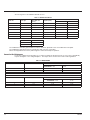
Connection Box Maintenance
For motors certied as Ex nA and Ex ec, in order to maintain the protection level, it is necessary to periodically
inspect and tighten covers and gland plates. The torque values shown below can be used for guidance:
Table 3-2 TORQUE VALUES
INCH-THREADED
BOLT SIZE THREAD PITCH STANDARD DRY TORQUE
FT. POUND FORCE
TOLERANCE +/- 5%
NEWTON METER TOLERANCE
+/- 5%
1/4 20 8.45 11.5
5/16 18 17.4 23.6
3/8 16 30.9 41.9
METRIC THREADED
BOLT SIZE THREAD PITCH STANDARD DRY TORQUE
FT. POUND FORCE
TOLERANCE +/- 5%
NEWTON METER TOLERANCE
+/- 5%
6 1.00 9.972 13.52
8 1.25 24.19 32.80
10 1.50 47.90 64.94
Page is loading ...
Page is loading ...
Page is loading ...
Page is loading ...
Page is loading ...
Page is loading ...
Page is loading ...
Page is loading ...
-
 1
1
-
 2
2
-
 3
3
-
 4
4
-
 5
5
-
 6
6
-
 7
7
-
 8
8
-
 9
9
-
 10
10
-
 11
11
-
 12
12
-
 13
13
-
 14
14
-
 15
15
-
 16
16
-
 17
17
-
 18
18
-
 19
19
-
 20
20
-
 21
21
-
 22
22
-
 23
23
-
 24
24
-
 25
25
-
 26
26
-
 27
27
-
 28
28


Baldor-Reliance RPM AC Direct Drive Type CTM Motor Cooling Tower Inverter Duty PM Motors (FL250, FL280, FL320, FL360, FL400, FL440 and FL580) Owner's manual
- Type
- Owner's manual
Ask a question and I''ll find the answer in the document
Finding information in a document is now easier with AI
Related papers
-
 Baldor-Reliance RPM XE Integral Horsepower AC Motors Totally Enclosed Owner's manual
-
 Baldor-Reliance RPM AC Inverter Duty Motors Owner's manual
-
 Baldor-Reliance AC Motors Frames 180 - 449 API 610 Style (P-Base) Vertical Mount Solid Shaft Owner's manual
-
 Baldor-Reliance AC and DC Mine Motors Owner's manual
-
Baldor-Reliance AC Water Cooled Mine Motors Owner's manual
-
 Baldor-Reliance Large A-C Motors 6800 Frame Horiz. Footless Water Cooled EXP Proof Mining Motor Owner's manual
-
 Baldor-Reliance AC Immersible Type Continuous In Air Motors Frame 210−449 600VAC and less Owner's manual
-
 Baldor-Reliance GOST Supplement for Explosion Proof Motors NEMA 180-449 (IEC 112S-280H) Owner's manual
-
 Baldor-Reliance RPM AC Inverter Duty Motors L400 Frames Vertical Mounting Owner's manual
-
 Baldor-Reliance Integral Horsepower DC Motors Owner's manual


Other documents
-
 Baldor-RelianceABB RPM AC Air-Cooled Condenser Owner's manual
-
König CS120MMFAN Datasheet
-
Greenheck Single/Three Phase Vari-Green Motor Quick start guide
-
ABB DMI DC Machines Owner's manual
-
Dodge Type K Flange, Wide Slot Take-Up, Top Angle Take-Up Owner's manual
-
-
-
Baldor DG3E User manual
-
-
Grundfos FB 25/65 Installation And Operating Instructions Manual
