Page is loading ...

Page 1 of 2 AR-M9922C Manual
Part No: 220010136
AR-M9922C Serial Manual
Version 1.01
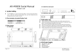
1. System Setting
The AR-M9922C for CPU board in output function at the front side board provides Power
LED, H.D.D LED, and LAN Link LED. The backside board also provides COM port, 3
LAN connector, 2 USB connector, Reset button and DC power jack output interface.
1.1 Main System
(1) Dimension: 195×125×38 (mm)
WANPWR USB COM LAN DMZ
RST
(2) Outlet (front side board)
(3) Outlet (backside board)
WANPWR
USB COM
LAN DMZ
RST
2. Fabrication way
Please remove the screw cover at the front and the backside board. After that, user
can open up the cover.
Please let the fixed nut of CPU board loose and remove it. At this time, user can
plug CF card and DRAM into CPU board.
Place the CPU board at the original site and then firmly fixed it by the fixed nut.
Upside down H.D.D are place into the bracket of H.D.D and attach the H.D.D. IDE
Cable. If the H.D.D is unused, user can directly place DOM over the IDE1
Finally, remove the screw cover that have been mentioned above and lock it to the
front and the backside board.

Page 2 of 2 AR-M9922C Manual
Part No: 220010136
3. The Fabrication Method of H.D.D Bracket
Please lock three copper pillars into CPU board, and then place the bracket of H.D.D
over the copper pillar by using mounting screw to lock it in accomplishing the fixing
action.
4. Power Supply
/