Page is loading ...

1
1. SAFETY INFORMATION
1.1 Safety notes
The gear unit is designed and constructed in accordance •
with the state of the art and is reliable in the condition
as shipped from our factory and installed in accordance
with these instructions. Unauthorized modications which
impair reliability are NOT allowed. This also applies to
removal of guards which are installed to prevent contact
with rotating parts.
The gear unit may only be used and operated within the •
scope of the conditions specied on the purchase order,
certied dimension drawing, and nameplate.
Do not operate the unit beyond its service rating. Failure •
may result in damage to property or injury to personnel.
The system of connected rotating parts must be free from •
critical speeds and vibrations -regardless of how they are
induced. This responsibility for this systems analysis lies
with the purchaser of the gear drive.
The user must ensure that the persons who will install, •
operate and maintain the drive have read and understood
this manual and follow these instructions to:
Prevent hazard to life and limb of the user and third •
parties
Ensure the reliability of the gear drive•
Prevent failure and environmental damage due to •
incorrect handling of the drive.
The relevant regulations concerning industrial safety •
and pollution control should be observed during the
installation, operation, and maintenance of the drive.
The gear unit may only be operated, serviced, and •
repaired by authorized, trained, and properly instructed
personnel.
All work should be carried out with safety in mind.•
All work on the gear drive must be carried out when the •
drive is stationary. The drive unit must be secured to
prevent accidental start up (for example by locking the
key switch or by removing the fuses in the power supply).
A notice should be displayed at the power control point
that work is in progress on the gear drive.
The drive unit should be shut off at once if changes in the •
gear unit are detected during operation such as abnormal
increases in operating temperature or a change in gear
unit noise level.
Rotating parts, such as couplings, shafts, belt drives, and •
WARNING: Because of the possible danger to persons(s) or property
from accidents which may result from the improper use of products, it
is important that correct procedures be followed. Products must be used
in accordance with the engineering information specified in the catalog.
Proper installation, maintenance and operation procedures must be
observed. The instructions in the instruction manuals must be followed.
Inspections should be made as necessary to assure safe operation under
prevailing conditions. Proper guards and other suitable safety devices or
procedures as may be desirable or as may be specified in safety codes
should be provided, and are neither provided by Baldor Electric Company
nor are the responsibility of Baldor Electric Company. This unit and its
associated equipment must be installed, adjusted and maintained by
qualified personnel who are familiar with the construction and operation
of all equipment in the system and the potential hazards involved. When
risk to persons or property may be involved, a holding device must be an
integral part of the driven equipment beyond the speed reducer output
shaft.
Installation, Maintenance and Repair Manual for
DODGE CYCLONE Standard Gear Units
These instructions must be read thoroughly before installation or operation.
gears must be protected by means of suitable guards to
prevent accidental contact.
These instructions should be incorporated into any •
manuals the system developer provides to the end user of
the drive system.
All nameplates afxed to the gear drive must be observed •
and followed. The nameplates should be kept free of paint
and dirt. Missing nameplates must be replaced.
2. GENERAL NOTES
These operating instructions are part of the gear unit shipment
and should be kept with the gear drive at all times.
Review of these instructions will assist in trouble free installation,
operation, and inspection of the gear drive.
NOTE: DODGE accepts no liability for damage or malunction
resulting from not following the instructions contained in this
manual.
The gear unit is designed to be operated within the parameters
specied on the nameplate of the drive as noted in Section 5.1.
Operating conditions which differ from those noted on the drive
requires review and approval by DODGE.
The gear drive is described in accordance with the design of
the unit at the time of printing of this manual. In the interest of
further development, we reserve the right to modify specic
assemblies and sub-assembles of the gear unit for particular
customer requirements or to enhance the function and safety of
the design.
For further information, please contact DODGE Product Support.
3. HANDLING
The gear unit is shipped assembled. Accessaries (such as heat
exchangers, couplings, guards) may be packaged separately.
The packaging of the gear drive may differ based on the unit size
and method of shipment.
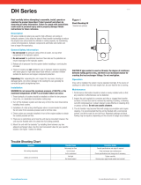
WARNING: When handling the gear unit, take care to avoid
damage due to the use of force or careless loading and
unloading. The gear unit may only be handled by using the
lifting provisions provided on the housing. Attach slings with
shackles to the lifting eyes. See Figure 1.

2
Figure 1
On gear units with lantern mounted motors, the center of gravity
will shift from the gear drive. In this case, add a sling to the motor
lifting bolt.
If the gear unit is mounted on a baseplate, special care is
required to prevent misalignment of the components during
handling.
The following symbols are used to indicate handling instructions.
Figure 2
4. STORAGE
The gear unit should be stored in a protected location in its
shipped position and covered.
CAUTION: Do not stack gear units on top of one another!
The internal parts are coated with preservative and the exposed
shafts are painted with a protective coating. The external coating
is resistant to weak acids, weak alkalis, oils, and solvents. It is
seawater resistant, humidity resistant, and heat resistant up to
284°F (140°C).
NOTE: Unless specified, DODGE warrants the internal
reservation for six months and the coating on the exposed
shafts for twelve months from date of shipment. In the case
of prolonged storage (greater than six months) check the
internal preservative and renew it if required. See Section
7.3.1 for Long Term Storage.
CAUTION: If the unit is stored outdoors, cover the gear unit
and prevent foreign matter and moisture from collecting on
the gear unit.
5. TECHNICAL DESCRIPTION
5.1 General Technical Data
The gear unit is supplied as a single, double, triple, or quadruple
stage helical or bevel helical gear drive. It is designed to be
mounted as noted on the dimension drawing provided with the
drive.
DODGE gear drives use the following product description:
H 3 S H 11
The rst letter is the type:
H - Helical Gear Parallel Shaft Drive
B - Bevel Helical Right Angle Gear Drive
The second number is the number of reductions:
1 - Single
2 - Double
3 - Triple
4 - Quad
The third letter is the output shaft type:
S - Solid shaft
F - Flanged shaft
H - Hollow shaft with key connection
D - Hollow shaft with shrink disk connection
The fourth letter is the mounting method:
H - Horizontal
M - Horizontal without feet
V - Vertical
The fth number is the unit size:
1 through 26.
The nameplate contains important technical information about
the drive.
Figure 3
1. Size
2. Ratio
3. Max. Input HP
4. Service Factor
5. Input RPM
6. Output RPM
7. Order Number
8. Serial Number
9. Special Notes
Further information can be found on the dimensional drawings
supplied with the unit.

3
5.2 Housing
The housing is made from cast iron, ductile iron, or fabricated
steel plate based on the application. A dipstick for checking oil
levels, oil drain plug for draining lubricant, and a vent plug for a
breather are provided. See Figure 4.
5.3 Pinions and Gears
Both pinions and gears are case hardened and ground. An
interference t as well as a key are used to connect the gears to
the shafting.
Figure 4
1. Housing
2. Lifting eyes
3. Cover
4. Shaft seal
5. Cover
6. Dipstick
7. Housing vent and breather
8. Cover
9. Oil drain plug
10. Nameplate
11. Foundation bolt location
5.4 Lubrication
Both gears and bearings are lubricated by splash lubrication.
On some units, a reducer driven pump or motor driven pump is
furnished depending on the application or customer requirement.
5.5 Bearings
All shafts are mounted on anti-friction bearings.
5.6 Shaft Seals
Labyrinth and contact type oil seals are used at shaft extensions
to prevent contamination to the gear drive and oil leakage.
Labyrinth seals do not contact the shaft and therefore never need
to be replaced.
5.7 Cooling
In most cases, gear drives are cooled by convection. In some
applications, fans, cooling coils, and heat exchangers may be
used.
5.7.1 Fan
The fan is mounted on the high speed shaft of the drive. Air is
drawn through the mesh grille of the fan guard and is directed
around the drive to increase air ow over the gear unit.
CAUTION: Clearance is required at the fan grille to allow for
sufficient air flow. Do not block the grille with couplings or
guards.
Dust covering the fan and the gear unit will reduce cooling
efciency.
5.7.2 Cooling Coil
The cooling coil is located in the oil sump of the gear drive. Fresh
water, sea water, or brackish water ow can be used in this coil.
Water can ow through either direction inside the coil.
CAUTION: The maximum cooling water pressure must not
exceed 115 psi (8 bar). In areas of frost with prolonged
shutdown of the drive, the water should be drained from
the coil. Water residue in the coil should be blown out with
compressed air.
To prevent high water pressures, use a pressure regulator on the
water inlet line.
5.7.3 Heat Exchanger
A heat exchanger is an external device used to cool the oil by
water or air. Review instructions provided by the heat exchanger
vendor for care and maintenance.
CAUTION: In areas of frost with prolonged shutdown of the
drive, the water should be drained from the heat exchanger.
5.8 Couplings
Couplings are normally used to connect the gear drive to the
driver and driven equipment.
If rigid couplings or items which induce additional radial and axial
loads on the shafting (such as pulleys, sprockets, and pinions)
are used, this should be reviewed by DODGE.
CAUTION: Couplings with surface speeds at maximum
diameter below 4000 ft/min (20 m/s) MUST be statically
balanced. Couplings above this surface speed require
dynamic balancing.
Review instructions provided by the coupling vendor for care and
maintenance.
5.9 Backstop
An optional feature is a mechanical backstop. During operation,
the backstop permits free rotation in one direction only. This
direction is marked on the gear drive input side by an arrow
indicating direction of rotation. The backstop is lubricated by the
gear drive. No external lubrication is required unless noted on the
dimension drawing.
NOTE: The direction of rotation can be changed by reversing
the cage. Contact DODGE for full instructions.
CAUTION: To prevent damage to or destruction of the
backstop, do not run in the opposite direction of rotation.
Proper rotation direction is marked on the gear drive input
shaft side.
6. INSTALLATION
6.1 General Information
Observe all safety directions while installing the gear drive. Before
installation, make sure that there is sufcient space around the
drive location for installation and maintenance.
6.2 Foundation
The foundation on which the gear unit will be mounted must
be at and horizontal. No vibration can be transmitted to the
gear drive from the foundation or adjacent foundations. Steel
structures used for mounting must be torsionally rigid and able to
carry all loads and torques imposed by the gear drive and other
equipment.
NOTE: Space requirements and foundation bolt locations are
found on the dimension drawing.
6.3 Installation Instructions
Remove corrosion protection from shaft extensions • with
solvent.

4
CAUTION: Follow directions and use caution when
applying solvent.
Mount input and output shaft drive elements. When •
parts are shrunk onto the shaft, do not heat above 275°F
(135°C). Remove exible elements before heating.
CAUTION: Follow operating instructions when
mounting couplings, sprockets and sheaves which are
provided with the product. Hammering or tapping on
the shaft is NOT permitted.
Before connecting the motor, the rotating eld of the 3 •
phase supply network should be determined with the aid
of a phase rotation indicator and the motor connected
according to the predetermined direction of rotation.
Align drive elements with the gear drive. It is critical to •
achieve exact horizontal alignment of the unit with the
prime mover and driven equipment. Precise alignment is
particularly important when mounting an overhung pinion
or installing an outboard bearing. Flexible couplings must
always be mounted according to prescribed alignment
tolerances to protect both the gear drive and the
couplings. Refer to the manufacturer’s recommendations.
The maximum deviation may not exceed 0.008 inch over 3
15/16 inch of shaft length (0.2 mm over 100 mm).
NOTE: The service life of the shafts, bearings, and
couplings are a direct function of the accuracy of the
alignment process.
Remove fan cover on Hl and H2 units to provide access to •
foundation bolts.
Tighten foundation bolts.•
CAUTION: The gear unit housing may not be stressed
while tightening the foundation bolts.
If there are external forces acting on the gear drive, secure •
the gear drive by means of dowels or stop blocks.
Replace fan cover on Hl and H2 units after tightening •
foundation bolts.
Fit safety devices on the gear unit.•
6.4 Shaft Mounted Units
Shaft mounted units require a torque arm. The connection
between the gear unit and the support must be exible.
6.4.1. Shaft mounted units with key connection
Remove corrosion protection from the inside of the hollow •
shaft and the shaft of the driven machine with solvent.
CAUTION: Follow directions and use caution when
applying solvent.
Check the dimensions of the bore and shaft to assure that •
there is not an interference t.
If not present, add a hole to the driven shaft for solvent •
access to be used during removal. See Figure 9.
Apply a lubricant to the surfaces of the hollow shaft and •
machine shaft for ease of installation.
Push the reducer onto the shaft by use of a threaded rod •
secured in the machine shaft. See Figure 5. A hydraulic
device can also be used.
Figure 5
Push the unit on gradually. DO NOT HAMMER.•
Secure the unit axially with an end plate.•
6.4.2. Shaft mounted units with shrink disk
connection
Remove corrosion protection from the inside of the hollow •
shaft and the shaft of the driven machine with solvent.
CAUTON: Follow directions and use caution when
applying solvent.
Check the dimensions of the bore and shaft to assure that •
there is not an interference t.
If not present, add a hole to the driven shaft for solvent •
access to be used during removal. See Figure 9.
Apply a lubricant to the surfaces of the hollow shaft and •
machine shaft for ease of installation. Do not apply grease
to inside bore of the hollow shaft under the shrink disk.
See Figure 6.
Figure 6
Push the reducer onto the shaft by use of a threaded rod secured
in the machine shaft. A hydraulic device can also be used.
Push the unit on gradually. DO NOT HAMMER.•
Take any three or four locking screws equally spaced •
and snug them up to establish a parallel or perpendicular
position of the shrink disk collar relative to the shaft. This
will properly seat the collars on the taper of the inner ring
and avoid cocking of the collars.
Using a torque wrench, tighten all locking screws •
gradually and all the way around in either clockwise or
counterclockwise sequence (not in diametrically opposite
sequence). Several passes are required until all screws are
torqued to the specied tightening torque.
Check and make sure that no screw will turn anymore by •
applying the specied tightening torque. Only then is the
installation complete.
Secure the unit axially with an end plate.•

5
7. START UP
7.1 Pre-start up activities
Verify the rating of the reducer (indicated on the nameplate •
and certied print) to be sure that the service rating and
speed are not exceeded in actual operation.
All exposed moving parts should be protected by guards.•
7.1.1 Preservative removal
Unscrew oil drain plug and drain off the remains of the •
preservative or test oil from the housing. Dispose of
properly.
Replace oil drain plug•
For units coming out of long term storage:•
Remove inspection cover from housing.•
Remove VPI bag from the housing.•
Figure 7
1. Inspection Cover
2. Dipstick
3. Vent plug/screw plug
4. Oil drain plug
7.1.2 Filling
Remove inspection cover from housing.•
CAUTION: Fill gear unit with fresh oil using a filling filter of 2.5
microns (60 µm). Add oil to all oil pockets over bearings and
the input shaft bearings on type B Bevel units.
NOTE: The oil used should meet all requirements outlined in
Section 10.5. Oil Viscosity and quantity required is found on
the nameplate of the gear drive.
NOTE: Fill the external lubrication system if the unit is so
equipped.
Check oil level with dipstick.•
NOTE: The oil level must be at the top mark on the dipstick.
Apply Loctite 572 sealant to the sealing face of the •
inspection cover following Loctite instructions.
Replace inspection cover.•
7.2 Start up
Check oil level with dipstick•
NOTE: When the oil has cooled down, the oil level should be
at the top mark of the dipstick. When the oil is hot, the oil
level may be above the top mark on the dipstick. The oil level
must never be below the lower mark on the dipstick. Add oil
to bring the level above this mark before operation.
If the unit is equipped with an oil cooling system, start •
water or air ow through the system.
If the unit is equipped with a backstop:•
Before start up, check that the shafts can be rotated •
in the correct direction without use of excessive force.
Check to make sure that the direction of rotation
matches the arrows on the input shaft side of the
drive.
CAUTION: To prevent damage to or destruction of the
backstop, do not run in the opposite direction of rotation.
Proper rotation direction is marked on the gear drive input
shaft side.
Before connecting the motor, the rotating eld of the •
three phase supply network should be determined
with the aid of a phase rotation indicator and the
motor connected according to the predetermined
direction of rotation.
7.3 Shutdown
To shut down the gear unit, shut off the driving equipment •
(prime mover).
CAUTION: Secure the drive assembly to prevent accidental
start up.
Shut off auxiliary equipment such as motor driven pumps, •
heat exchangers, water ows.
CAUTION: In the case of water - oil coolers and cooling coils,
drain the water from the system to prevent frost damage.
NOTE: If shutdown is for a long period of time, the gear drive
should be run briefly at three week intervals. If shutdown is
longer than six months, see Section 7.3.1.
7.3.1 Long Term Storage
Two methods are available for long term storage based on oil seal
type and auxiliary equipment are available.
7.3.1.1 Storage for units with splash lubrication and
contact oil seals
For units with contact type oil seals, splash lubrication, and/or
without drywells, the unit can be lled to level with the vent plug
with the operating oil.
7.3.1.2 Storage for units with labyrinth oil seals, oil
circulating systems, or drywells
Gear drives with labyrinth oil seals, pressurized oil lubrication,
or drywells should be run in no-load mode with preservative
before long term storage.
Storage Time Preservative Special Measures
Mineral Oil
up to 18 months Shell Ensis Fluid SDC none
up to 36 months Shell Ensis Fluid SDC
and
Shell VPI Powder 260 ①
seal gear unit, replace
and vent plug with sealing
plug (change on start-up)
Synthetic Oil
up to 18 month Special corrosion inhibitor
oil TRIBOL1390
none
up to 36 months Special corrosion inhibitor
oil TRIBOL 1390 and Shell
VPI Powder 260 ①
seal gear unit, replace
vent plug with sealing plug
(change on start up)
CAUTION: ① Change VPI bag every two years.
Shut off gear unit and drain oil as described in Section 10 •
Maintenance and Repair
Pour in preservative in accordance with the above Table •
through the vent hole or through the inspection cover
opening up to the top mark on the dipstick.
Cap the vent hole or replace the inspection cover.•
Run gear unit under no-load briey.•
Drain preservative from gear drive and dispose of properly.•

6
CAUTION: The preservative may be hot! Wear protective
clothing. Ensure proper ventilation of area.
Replace the oil drain plug•
If storage is longer than 18 months, remove inspection •
cover, suspend VPI bags (one 2.7 oz bag per 18 ft
3
of air)
(one 25 g bag per 0.5 m
3
of air) inside the gear drive, apply
Loctite 572 sealant to the sealing face of the inspection
cover following Loctite instructions, replace inspection
cover, and replace vent plug with sealing plug.
NOTE: Before starting the gear drive, remove the VPI powder
bags and replace the screw plug with the vent cap.
7.3.2 External preservative procedure
Protection Time Preservative Name Coating Thickness Remarks
up to 12 months Tectyl 846 K19
approximately
0.002 inch
(50 µm)
Was based
preservative
seawater resistant
and tropic proof
Clean shaft surfaces.•
Coat shaft seal rings with grease for protection against the •
preservative.
Apply preservative.•
8. OPERATION
During operation, the gear unit should be checked for:
Excessive operating temperature (The gear unit is •
designed for continuous service with a maximum oil sump
temperature of 200°F (93°C) or a maximum of 100°F (55°C)
rise above ambient, see Section 10 Maintenance and
Repair)
Any changes in gear unit noise level.•
Oil leakage at the housing and shaft seals.•
Correct oil level (see Section 7 Start up).•
NOTE: To check the oil level, shut off the driving equipment.
When the oil is hot, the oil level may be slightly above the
top mark on the dipstick. Do not operate the gear drive with
an oil level below the bottom mark on the dipstick. Add oil if
required.
CAUTION: If irregularities are detected during operation
or the pressure monitor in the oil cooling system trips an
alarm (if so equipped), the drive assembly should be shut
off immediately. The cause of the malfunction should be
determined with the aid of the Troubleshooting Table (Section
9). This table lists possible malfunctions, their causes,
and suggestions for correction. If the cause can not be
determined, please contact DODGE.

7
9. TROUBLESHOOTING
NOTE: Malfunctions occurring during the warranty period which necessitate repair of the gear unit may only be performed
by DODGE personnel. Even after the warranty period. we recommend users to consult Product Support with respect to
malfunctions in which the cause can not be determined.
Malfunction Possible Cause Remedy
Temperature rise at bearing locations Oil level ingear unit housing is too low. Check oil level; add if required
Oil is too old Check when oil was last changed;
changed oil if required; see Section 10
Mechanical oil pump is defective Check oil pump; replace if required
Bearing(s) have failed Call DODGE Product Support; check
bearing(s); replace if required
Excessive operating temperature Oil level in gear unit is too high Check oil level; lower if required
Oil is too old Check when oil was last changed; change
oil if required; see Section 10
Oil is very dirty Change oil, see Section 10
Gear unit has oil cooling system with
insufcient collant ow rate
Open valves in inlet and outlet lines; check
cooling coil for free ow; check water-oil
cooler for free ow; check air-oil cooler for
free ow
Coolant temperature is too high Check temperature and correct if required
Oil ow rate through heat exchanger is too
low due to a clogged oil lter
Clean oil lter; see Section 10
Oil ow rate through heat exchanger is
toolow due to a defective oil pump
Check function of oil pump; repair or
replace pump if required
Unit is coated with dust Clean gear unit housing
Gear units with fan: intake opening in fan
cover and/or gear unit housing is clogged
Clean fan cover and gear unit housing
Change in noise level of gear unit Damage to gear teeth Call DODGE; check pinions and gears;
replace damaged components
Excessive bearing play Call DOGE; adjust bearing endplay
Defective bearing Call DODGE; replace defective bearing
Defective coupling Call coupling vendor; replace coupling
Loud noises from the gear unit mounting Gear unit mounting has loosened Tighten bolts/nuts to recommended
tightening torque. Replace damaged bolts/
nuts
Gear unit is oily Inadequate sealing of housing cover or
joints
Check seals; replace if required; seal joints
Radial shaft seals defective Check seals; replace if required
Oil level in gear unit is too high Check oil level; lower if required
Vent is clogged Check vent; replace if required
Oil is leaking from drain plug Check plug; drain unit and replace plug if
required
Oil Pressure monitor trips alarm (on units
so equipped)
Oil pressure less than 7 psi (0.5 bar) Check oil level, add oil if required; check
function of oil pump, repair or replace
pump if required, check oil lter, clean if
required, see Section 10

8
Measures Periods Comments
Check oil temperature daily
Check gear unit noise level changes daily
Check oil level monthly
Check gear unit for leakage monthly
Check oil for water content After approximately 400 operating hours / at least
once per year
see 10.2.1
Initial oil change after start up After approximately 400 operating hours see 10.2.2
Subsequent oil changes Every 18 months or 5000 operating hours see10.2.2
Clean oil lter Every three months see10.2.3
Clean fan At same time as oil change see10.2.4
Check all mounting hardware for tightness After rst oil change, then after every other oil change see 10.2.5
Check cooling system At same time as oil change see 10.2.6
Perform complete inspection of gear drive Approximately every two years when changing oil see 10.2.7
Grease bearings As marked on gear drive see 10.2.8
Grease seals As required see 10.2.9
NOTE: If conditions are different from above, the periods
should be adjusted accordingly.
10.2 Description of maintenance and repairs
10.2.1 Examining oil for water content
Have the lubricant supplier perform an oil analysis at the time
of the oil change. Consider setting up an oil sampling plan to
determine the optimal time to change the lubricant based on its
condition.
10.2.2 Performing oil changes
CAUTION: When changing the oil, the gear unit should always
be filled with the same oil grade as previously used. Mixing
oils of different grades or manufacturers are NOT allowed. In
particular, synthetic oils may not be mixed with mineral oils
or different synthetic oils. When changing over from mineral
oil to synthetic oil or from synthetic oil with a particular
based to synthetic oil with another base, the gear unit must
be flushed thoroughly with the new oil.
When changing the oil, the housing must be cleaned thoroughly
by ushing with oil to remove oil sludge, contamination, and
residues of old oil. For this purpose, the same oil grade should be
used as used for operation. Highly viscous oil should be warmed
before use. Once all residue has been removed, add the new oil.
NOTE: The oil change must be carried out
immediately after shutdown of the gear unit.
Figure 8
1. Inspection Cover
2. Dipstick
3. Vent plug/screw plug
4. Oil drain plug
Shut down gear unity by shutting off the drive unit.•
CAUTION: Secure the drive assembly to prevent accidental
start up.
Shut off valves in the coolant inlet and outlet lines (if so •
equipped).
Unscrew the vent plug on the top of the housing.•
Unscrew the oil drain plug and drain oil into a suitable •
container.
CAUTION: Scalding risk is present from the hot oil. Wear
protective clothing.
Thoroughly clean the permanent magnet of the oil drain •
plug
Replace the oil drain plug in the housing•
10. MAINTENANCE AND REPAIR
10.1 General information on maintenance
NOTE: All maintenance and repair work shouid be carried
out with due care and only by trained personnel. Observe all
safety precautions.
CAUTION: The periods listed in the table below are
dependent on the duty cycle of the gear drive. Recommended
values are based on the following:
24 hour per day running time•
100% full load•
input speed of 1800 rpm•
maximum oil temperature of 200°F (93°C)•

9
NOTE: Check condition of the seal washer in the drain plug,
use a new oil drain plug if required.
Clean oil lter in lubrication system (if so equipped). See •
Section 10.2.3.
Following lling instructions in Section 7.1.2.•
10.2.3 Cleaning the oil filter
See the operating instructions supplied with the oil lter.
10.2.4 Cleaning the fan
Shut down the gear unit by shutting off the drive unit.•
CAUTION: Secure the drive assembly to prevent accidental
start up.
Remove the fan housing•
Remove dirt adhering to the fan, housing, and cover with a •
stiff brush.
Remove any corrosion present.•
Replace the fan cover on the gear drive.•
10.2.5 Checking fasteners
Shut down the gear unit by shutting off the drive unit.•
CAUTION: Secure the drive assembly to prevent accidental
start up.
Shut off valves in the coolant inlet and outlet lines (if • so
equipped).
Check all fasteners for tightness with a torque wrench.•
Thread size Property
Class
Tightening Torque
M 10 10.9 530 Ibs in 60 Nm
M 12 10.9 885 Ibs in 100 Nm
M 16 10.9 2210 Ibs in 250 Nm
M 20 10.9 4425 Ibs in 500 Nm
M 24 10.9 7700 Ibs in 870 Nm
M 30 10.9 15490 Ibs in 1750 Nm
M 36 10.9 30980 lbs in 3500 Nm
NOTE: Damaged screws should be replaced by new
fasteners of the same class and type.
10.2.6 Checking the heat exchanger and cooling
coil
Shut down the gear unit by shutting off the drive unit.•
CAUTION: Secure the drive assembly to prevent accidental
start up.
Shut off valves in the coolant inlet and outlet lines. Shut off •
the motor on oil - air coolers.
Check conditions of the heat exchanger in accordance •
with the Operating Instructions provided by the
manufacturer.
Check for fouling in the cooling coil. Replace if fouling is •
severe.
NOTE: Check fasteners for tightness; replace if required.
Run gear unit briey.•
Shut down gear drive and check oil level with dipstick.•
NOTE: The oil level must come up to the top mark on the
dipstick.
If oil is required, see Section 7.1.2 for lling instructions.
10.2.7 Gear unit inspection
The gear unit inspection can be preformed by DODGE service
personnel for a complete evaluation of the condition of the gear
drive and required replacement parts.
10.2.8 Grease bearings
In some gear units, grease is provided for bearing lubrication.
Units are greased before shipment. The intervals and the
amounts required for re-greasing are shown on a label next to the
grease tting.
10.2.9 Greased shaft seals
Grease packed shaft seals must be re-greased depending on the
contamination of the seal area.
10.3 Removal of shrink disk
Shut down the gear unit by shutting off the drive unit.•
CAUTION: Secure the drive assembly to prevent accidental
start up.
Loosen all tightening bolts uniformly around the bolt circle •
several times - a quarter turn each time. Never unscrew
any of the bolts completely.
Remove any rust in the vicinity of the shrink t.•
Pull the shrink disk from the hub.•
10.4 Removal of shaft mounted drives
Shut down the gear unit by shutting off the drive unit.•
CAUTION: Secure the drive assembly to prevent accidental
start up.
Inject a rust solvent through the solvent access in the •
machine shaft
Remove the end plate•
Use a xture as shown in Figure 9 for pulling the unit off •
the shaft - NEVER HAMMER. Insert the xture bolts in
the threads of either the hollow shaft, housing, or bearing
cover, as required. A hydraulic device can also be used.
Figure 9

10
If the ambient temperature is outside this range, consult DODGE
for oil viscosity recommendations.
The lubricant viscosity is shown on the nameplate of the •
gear drive.
The SSU values are rounded mean values of •
corresponding SSU viscosity ranges.
The permitted variation of each ISO VG class is ±10%. •
Units with grease lubricated bearings are furnished •
with a lithium saponied grease. Greases with different
saponication bases should not be mixed.
All mineral based EP oils are the preferred lubricant. •
suitable for operating temperatures up to 195°F (90°C) as
well as for low ambient temperatures down to 25°F (-4°C).
For lower temperatures or critical applications. we suggest
synthetic lubricants which are suitable for operating
temperatures up to 212°F (1 Q00C) as well as for low
ambient temperatures down to -15°F (-26°C).
NOTE: DODGE has reviewed the above iubricants listed
in this manual and they have met our criteria at time of
publication of this manual. Therefore, we recommend that
the end users should select a lubricant from the above
table, taking into account the viscosity range stated on the
nameplate.
NOTE: The above recommendation does not imply release of
warranty for the quality of lubricant provided by the lubricant
supplier. Each lubricant manufacturer must warrant the
quality of his product themselves.
If an oil not listed in the above table is selected, DODGE will
assume no responsibility for the suitability of the lubricant in
our products. In order to minimize technical risk in selecting a
lubricant not listed in the above table, the selected lubricant must
meet the following criteria:
All oil iubricants are extreme pressure oils (EP) and have 1.
passed 12 stages in the FZG test.
All oil lubricants have passed 10 stages in the FVA project 2.
54 mircopitting test.
The foam content of the oil may not exceed 10% per the 3.
DODGE FOAM TEST.
The oil must be compatible with 72 NBR 902 and 72 FKM 4.
585 seal ring materials.
The oil must be compatible with DODGE standard paints 5.
and interior coatings.
11. SPARE PARTS
A stock of the most important replacement parts on site is critical
for minimizing downtime and maintaining the gear drive.
Recommended spare parts are as follows:
1 set bearings
1 set contact type oil seals
For critical service, additional rotating parts may be required.
We assume warranty for only original spare parts furnished by
DODGE.
CAUTION: Spare parts not furnished by DODGE have not
been tested for compatibility with the gear drive. Using such
parts may adversely effect the performance and safety of
the gear drive. No warranty or guarantee will be assumed by
DODGE for damage caused by spare parts and accessories
not furnished by DODGE.
When ordering spare parts, please supply the Order Number, Unit
Size, Part Number, and quantity. The rst two items can be found
on the nameplate of the gear drive.
Viscosity Grade at 100° F Mineral Lubricant Synthetic Lubricant
AGMA
Grade
SSU
ISO VG
Class
KLUBER MOBIL SHELL TRIBOL TRIBOL KLUBER
8 EP 3200 VG 680
KLUBEROIL
GEM 1/680
Mobilegear
636
OMALA
680
Tribol
1100/680
Tribol
800/680
SYNTHESCO
D680EP
7 EP 2200 VG 460
KLUBEROIL
GEM 1/460
Mobilegear
634
OMALA
460
Tribol
1100/460
Tribol
800/460
SYNTHESCO
D460EP
6 EP 1500 VG 320
KLUBEROIL
GEM 1/320
Mobilegear
632
OMALA
320
Tribol
1100/320
Tribol
800/320
SYNTHESCO
D320EP
5 EP 1100 VG 220
KLUBEROIL
GEM 1/220
Mobilegear
630
OMALA
220
Tribol
1100/220
Tribol
800/220
SYNTHESCO
D220EP
4 EP 700 VG 150
KLUBEROIL
GEM 1/150
Mobilegear
629
OMALA
150
Tribol
1100/150
Tribol
800/150
SYNTHESCO
D150EP
3 EP 470 VG 100
KLUBEROIL
GEM 1/100
Mobilegear
627
OMALA
100
Tribol
1100/100
Tribol
800/100
SYNTHESCO
D100EP
Bearing
Greases
EXXON MOBIL SHELL TEXACO TRIBOL
BEACON 3
Mobilith
AW 2
Alvania R2 Multifak 2 Molub-Alloy 860/220-2 Tribol 4020-220-2
10.5 Lubricants
The required oil viscosity (VG Class) is specied on the nameplate
of the gear drive. This viscosity is valid for normal operating
conditions at an ambient temperature range of 25°F to 86°F (-4°C
to 30°C) for mineral oils and -15°F to 104°F (-26°C to 40°C) for
synthetic.

11

World Headquarters
P.O. Box 2400, Fort Smith, AR 72902-2400 U.S.A., Ph: (1) 479.646.4711, Fax (1) 479.648.5792, International Fax (1) 479.648.5895
Dodge Product Support
6040 Ponders Court, Greenville, SC 29615-4617 U.S.A., Ph: (1) 864.297.4800, Fax: (1) 864.281.2433
www.baldor.com
© Baldor Electric Company
MN1604 (Replaces 499334)
All Rights Reserved. Printed in USA.
1/10 PRINTSHOP 100
*1604-0110*
/