
PV500-21B 08-98 1 Section 21B
INSTALLATION & MAINTENANCE MANUAL FOR
PVI FIREPOWER
BG600 GAS BURNER
1,200,000 thru 2,400,000 Btu/h
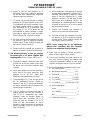
CARBON MONOXIDE WARNING:
CAUTION: IMPROPER COMBUSTION MAY CAUSE SERIOUS INJURY.
PVI recommends a seasonal or annual combustion check-out be performed by a
qualified service agency to ensure safe and efficient operation.
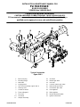
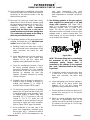
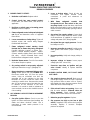
Typical Construction
Figure 21B-1
1.
Burner housing
12.
Air switch
2.
Mounting flange
13.
Manual gas valve
3.
Blast tube
14.
Gas inlet
4.
Flange gasket
15.
Common electr
ic gas valve
5.
Gas nozzle assembly (Figure 21B
-
2)
16.
Main electric gas valve
6.
Housing cover
17.
Pilot electric gas valve
7.
Control enclosure
18.
Pilot regulator
8.
Flame safeguard
19.
Main regulator
9.
Fan motor
20.
Nozzle adjustment plate
10.
F
an wheel
21.
Ignition transformer
11.
Damper assembly

PV500-21B 08-98 2 Section 21B
PVI FIREPOWER
BG600 GAS BURNER
CAUTION: CONDUCT THE FOLLOWING GAS TRAIN LEAKAGE TEST BEFORE START-UP, AT
ANNUAL INTERVALS AND PRIOR TO INVESTIGATING THE CAUSE OF ANY REPORTED
OCCURRENCES OF DELAYED IGNITION.
1. Using an appropriate bubble detection
solution, thoroughly coat all gas train pipe
connections. If any bubbles are detected, the
leaking connection must be tightened,
recoated and rechecked to assure stoppage
of the leak.
2. Attach a manometer, to measure gas
pressure, at the manual gas shutoff valve
located just upstream of the gas train. Adjust
gas train inlet pressure to the specified value
(e.g. 14 in. W.C.), and tightly close the gas
train manual shutoff valve closest to burner.
3. Reattach the manometer to the gas train
manual shutoff valve at the burner and
record the measured gas pressure in inches
of water column (in W.C.). Measure gas
pressure again after 15 minutes. If gas
pressure has increased 0.5” W.C. or more,
the gas leak must be isolated to one or more
of the operating gas valves, for example, a
solenoid actuated gas shutoff valve. After
any leaking valve is replaced, the
reassembled gas train must be leak tested
again before start-up is attempted. (NOTE:
All gas valves removed because of
suspected leakage must be returned to PVI
Customer Service for disposition.)
ELECTRICAL
1. Wiring to the unit should conform to the
National Electrical Code or the code legally
authorized to your locality. A fused
disconnect switch should be used for water
heater control. Service wiring connections of
120V, 1 phase, 60 Hz. are located in the
enclosure on water heater. (See Figure 21B-
8, page 10.)
2. A proper earth ground for this unit must be
provided. PVI recommends a single
conductor ground wire be pulled from the
distribution panel to the sub panel (or some
similar type).
NOTE: Use only copper wire of proper sizing
for incoming service. Damage resulting from
use of aluminum wiring will be excluded
from coverage under warranty of this unit.
FOR YOUR SAFETY
WHAT TO DO WHEN
YOU SMELL GAS:
• DO NOT try to light any
appliance
• DO NOT touch any electrical
switch; DO NOT use any
phone in your building.
• IMMEDIATELY call your gas
supplier from a phone
outside the building. Follow
the gas supplier’s
instructions.
• If you cannot reach your
gas supplier, CALL THE
FIRE DEPARTMENT.
FOR YOUR SAFETY
DO NOT store or use gasoline
or other flammable vapors and
liquids in the vicinity of this or
any other appliance.
FOR YOUR SAFETY
WARNING: Improper
installation, adjustment,
alteration, service or
maintenance can cause injury
or property damage. Refer to
this manual for assistance, or
consult a qualified installer

PV500-21B 08-98 3 Section 21B
PVI FIREPOWER
BG600 GAS BURNER START-UP
(Refer to Figure 21B-1 to identify burner parts)
1. Remove the enclosure panel cover on the water
heater or boiler to expose the control circuit.
Located on the backside of this cover is a wiring
diagram. This diagram will show the controls
used in our circuitry.
2. Visually check that all components are intact
and no damage has occurred during transit.
Check all connections within the control cabinet.
A loose connection could cause intermittent
shutdowns.
3. The burner control system provides spark
ignition and flame safeguard. On a call for heat,
the burner motor circuit is energized. The air
flow switch circuit closes. Following a short time
delay (prepurge) the gas valve(s) opens and
ignition occurs.
NOTE: Do not tamper with or readjust program
dipswitch settings. This will cause the control to
become inoperable. Damage resulting from
tampering will be excluded from coverage under
the warranty of this unit.
4. Remove flame safeguard control from its base.
Check connections in control mounting base;
loose connections can cause nuisance
shutdowns. When applicable, check time card or
programmer, for good connection. NOTE:
Always secure gas lines; tag "Out of
Service" before servicing burner nozzle or
electrodes.
5. Pull nozzle assembly to check flame and ignition
electrodes. See Figure 21B-8, page 8.
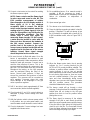
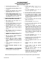
6. With electrodes exposed, check them for the
proper settings as stated in Figure 21B-2, page
3. Check for any hairline cracks in the insulators.
Should replacement of burner electrodes be
required, certain procedures must be followed.
In all cases, removal of the electrodes is
accomplished by loosening the electrode
mounting clamps. Draw the electrodes out of the
nozzle assembly through holes in pressure
plate.
7. Inspect electrodes for cracked ceramic or loose
retaining studs that hold the wire within the
ceramic. Select the proper pressure plate hole
to place each electrode and insert electrode
through the hole, retaining stud end first.
8. Tighten the electrode mounting clamp slightly
until electrode ceramics are seated firmly and
completely in the mounting bracket without gaps
between ceramics and mounting bracket at the
bearing faces.
9. Measure and set electrodes according to Figure
21B-2, pg. 3. After the gaps and setting are
complete, fully tighten electrode mounting
clamp. Be careful not to overtighten or allow
electrodes to impinge on pressure plate
opening; insulation may crack.
Figure 21B-2
10. Replace nozzle assembly; be sure to connect
the flame and spark rod wires before installing
nozzle assembly fully into blast tube. Check
connections on the ends of the flame and spark
rod wires for good contact. Look for properly
stripped wire ends. Be sure connectors are
firmly attached to flame and ignition rod ends.
Insulating boots can give a false feeling of
proper seating. DO NOT MOVE
ELECTRODES. Be careful not to bump
electrodes. Check fan wheel for free rotation.
11. Reinstall orifices in unions (if required). Reinstall
gas nozzle assembly.
12. The following test equipment is required:
a) Manometer or suitable gauge for measuring
up to 28" W.C. for checking gas pressure.
b) Draft gauge for determining draft in stack.
c) Combustion analyzer which measures O
2
or
CO
2
, CO and stack temperature.
d) AC/DC multimeter.
e) Ammeter
f) Potentiometer (modulating burners only)

PV500-21B 08-98 4 Section 21B
PVI FIREPOWER
BG600 GAS BURNER START-UP (con't)
13. Connect a test meter to the control for reading
the flame response signal.
NOTE: Some controls read the flame signal
in micro amps and some in volts DC. The
E110 provides measurement of relative
flame strength on its LCD display module. A
flame signal of 10 is the minimum
acceptable; 20-80 is normal. The MC120
series control has two terminals marked for
reading volts DC. A flame signal of 4.0 to 6.0
volts (for UV amplifiers) and 14-18 volts (for
flame rectification amplifiers). The S89
control uses a micro amp signal for
measuring flame strength. For this control,
a meter must be hooked in series with the
flame rod wire. Disconnect the leadwire at
the S89 sensor terminal. Connect the
positive lead of the meter to the quick-
connect sensor terminal on the S89 and the
negative lead to the free end of the sensor
leadwire. Normal flame signal strength
should be printed on the control case.
14. Be sure the tank is filled with water. Once the
burner is reassembled, two devices to read
pressure, preferably U-tube manometers, will be
needed to read gas pressures. Connect one to
read the inlet pressure of burner. This is the
pressure measured before all components in the
gas train. The manometer must stay connected
throughout the testing, as the inlet pressure
must be monitored during the firing of the
burner. Record static pressure; it must not
exceed the maximum inlet pressure of either
regulator. This pressure will be recorded on
each regulator. Pressures above this could
cause damage to the diaphragm in the gas
valve or pressure regulator.
15. Drill ¼" test hole in stack approximately 8" from
vent connection (before the draft regulator).
16. Check terminal L1 and L2 in control cabinet to
determine if proper control voltage has been
supplied.
17. With fuel selector switch or burner power switch
in off position, turn on main power switch, and
reset low water cutoffs located in control cabinet.
18. Check to determine if correct voltage has been
supplied to the blower motor.
19. For modulating burner: if no manual control is
provided, it will be necessary to install a
potentiometer in place of the modulating control
devise for evaluation or adjustment of
combustion.
20. Open manual gas valve.
21. Turn burner on to check blower motor rotation.
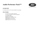
22. Place the high/low manual-auto switch in low fire
position, if supplied. This will lock burner in low
fire. If the burner is supplied with a Landis & Gyr
SQM5 modulation motor, refer to Figure 21B-3,
below.
Figure 21B-3
23. When the blower motor starts, the air proving
indicator (or 3 to P running interlock) on the
MC120 or E110 control should be satisfied. This
indicates a positive airflow condition. If the air
proving indicator is not on, turn air proving
switch adjustment screw counter-clockwise until
the air proving light comes on, then turn screw
one turn counter-clockwise. If the gas valves
open and close intermittently during normal
operation, turn screw one half counter-clockwise
until this condition ceases. This procedure
should be followed with every burner.
24. The burner control will go through a short
prepurge. During that time the modulating motor
should drive the air shutter to the full open
position then back to low fire position before
pilot ignition occurs.
25. The flame signal (a measure of the relative
strength of the pilot or main flame) should be
within the control manufacturers specified range.
If the pilot fails to light during the initial period,
check for air in the line. The control will lockout.
Press the flame safeguard reset button to reset
burner and begin the purge cycle again.

PV500-21B 08-98 5 Section 21B
PVI FIREPOWER
BG600 GAS BURNER START-UP (con't)
26. Once the pilot flame is established, set the pilot
pressure (measure at the shutoff valve closest to
the burner) at the pressure shown on the tag
attached to the gas train.
27. Now open the main gas shutoff valve slowly.
Allow burner to fire for at least 5 minutes or until
the stored water temperature is at least 120°F.
Premature testing can result in inaccurate
combustion readings. NOTE: Condensate
coming from the tubes on a cold start is
normal and does not indicate a leaking tube.
This condensate will appear at the fitting in
the lower part of the flue collector.
28. The following pertains to flue gas analysis when
supplied, for natural gas or LP with fixed input
control. Refer to Figure 21B-4, page 7.
a) Readings need to be taken from a hole in
the vent several inches downstream of flue
outlet connection but below the draft
regulator.
b) Insert draft gauge into the test opening in
stack. Draft in the stack should read
between -.02 to -.06" W.C. Adjust draft
regulator to bring draft within this range.
c) Check the manifold gas pressure. If set at
the factory specified pressure in ("WC),
proceed to paragraph (d). If the manifold
gas pressure is too low, increase the gas
pressure by adjusting the main gas
regulator clockwise; decrease by turning
counter-clockwise.
d) Gradually close air damper to decrease O
2
reading or open air damper to increase O
2
reading until optimum O
2
% (4-6%) is
reached. Refer to Figure 21B-6, page 8.
e) CO should not exceed 100 ppm. A reading
greater than 100 ppm indicates a lack of air
or misadjusted gas nozzle assembly. Open
air damper slightly or reduce firing rate,
exceeding 6% O
2
if necessary; note any
change in CO. If CO levels are still
unacceptable or burner pulsates it may be
necessary to adjust gas nozzle assembly.
Refer to Figure 21B-6, page 8 for details.
f) Once combustion is set, take note of the
gross stack temperature; maximum gross
stack is to be 400° F, minimum net stack is
to be 300°F. (NOTE: Net temperature is the
total stack temperature, less room
temperature.) If an excessively high gross
stack temperature is recorded, consult the
factory.
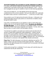
29. The following pertains to flue gas analysis,
when supplied, for natural gas or LP with
air/gas ratio controller. (See Figure 21B-5,
page 7.) For adjustment of the air/gas ratio
controlling actuator, refer to Figure 21B-4,
below. The high fire ratio and low fire bias
adjustment screws are located on the top of the
regulator under a sealed covered plate. The
actual settings can be seen through a window
on each side of the regulator.
Figure 21B-4
NOTE: The burner firing rate is controlled by
the movement of the air damper. The
combustion quality (air/gas ratio) is
controlled by the settings on the regulator
(the + and – indications relate to the change
in gas flow).
a) Combustion samples should be taken from
a small hole in vent several inches from
boiler vent connection but below draft
regulator.
b) Insert draft gauge into the test opening in
stack. Draft in the stack should read
between -.02 to -.06" W.C. Adjust draft
regulator to bring draft within this range.
c) Set the gas flow at low fire to achieve an O
2
content in the vent gas of 5 to 7% (low fire
bias adjustment).
d) Switch to manual modulation and increase
firing rate to approximately 90% of full
capacity and set the gas flow to achieve an
O
2
content in the vent gas of 4 to 6% (high
fire ratio adjustment).

PV500-21B 08-98 6 Section 21B
PVI FIREPOWER
BG600 GAS BURNER START-UP (con't)
e) Return to low fire and measure O
2
. If
necessary, correct the setting by adjusting
the low fire bias. Repeat these steps until
optimum values are obtained.
f) CO should not exceed 100 ppm. A reading
greater than 100 ppm indicates a lack of air
or misadjusted gas nozzle assembly. Open
air damper slightly slightly or reduce firing
rate, exceeding 7% O
2
if necessary; note
any change in CO. If CO levels are still
unacceptable or burner pulsates it maybe
necessary to adjust gas nozzle assembly.
Refer to Figure 21B-7, page 8 for details.
g) Once low and high fire combustion has been
set, take an O
2
and CO reading at 5 equally
spaced inputs. These readings should met
the criteria in steps (c) and (d).
h) Confirm that the manifold gas pressure at
high fire is correct to achieve full rated input.
30. The following pertains to flue gas analysis
for natural gas or LP when supplied with
metering valve. (Refer to Figure 21B-5, pg. 7.)
a) Combustion samples should be taken from
a small hole in the vent several inches from
the burner vent connection but below draft
regulator.
b) Insert draft gauge into the test opening in
stack. Draft in the stack should be read
between -.02 to -.06" W.C. Adjust draft
regulator to bring draft within this range.
c) The percentage of O
2
in the vent gas at low
fire, for modulating burners, should be
between 5 and 7%. If O
2
does not fall within
this range, adjust air and/or fuel pressure to
achieve proper combustion.
d) The CO should not exceed 100 ppm. A
reading greater than 100 ppm indicates a
lack of air or misadjusted gas nozzle
assembly. Open air damper slightly or
reduce firing rate, exceeding 7% O
2
if
necessary; note any change in CO. If CO
levels are still unacceptable or burner
pulsates it maybe necessary to adjust gas
nozzle assembly. Refer to Figure 21B-6,
page 7 for details.
e) Once combustion is set properly at low fire
and the water temperature is at least 100°F,
manually control burner to high fire, repeat
steps (c) and (d), adjusting the O
2
range
between 4 and 6%. This will apply to both
fixed input and modulating burners. All
adjustments on modulating burners should
be made at low fire, so as to not to disturb
previous low fire settings.
f) Confirm the manifold gas pressure is
correct, so as to achieve full rated input.
g) Once low and high fire combustion has been
set, take an O
2
and CO reading at 5 equally
spaced inputs. These readings should met
the criteria in steps (c) and (d).
NOTE: Never change fuel or air adjustment
without first consulting with PVI Customer
Service or an authorized service company.
31. Make sure air shutter is locked securely in
place. (Refer to Figure 21B-6, page 8.)
32. Check each operating and limit control to be
sure they function properly by lowering and
raising the temperature setting on each of the
controls, causing the burner to cycle on and off.
33. Record the following information for future use:
a) Air shutter position ________________
b) Manifold gas pressure_________" W.C.
c) Stack draft _________________" W.C.
d) O
2
reading _______________% (4-6%)
e) CO
2
reading ______________% (8-9%)
f) CO reading _______% (less than .03%)
g) Stack temperature:
Gross ________________________°F.
Less ambient ___________________°F.
Net __________________________°F.
h) Combustion efficiency _________

PV500-21B 08-98 7 Section 21B
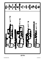
Gas Train
Figure 21B-5

PV500-21B 08-98 8 Section 21B
PVI FIREPOWER
BG600 GAS BURNER START-UP (con't)
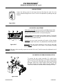
AIR ADJUSTMENT
Loosen the locking screw (A) and move the lever (B) along the scale (C) to the
position wanted and tighten the screw. Check the air adjustment by making a flue gas
analysis.
Figure 21B-6
GAS NOZZLE ADJUSTMENT
High carbon monoxide can be caused by a misaligned gas nozzle
assembly. Turning the adjustment screw (D) clockwise will retract
the gas nozzle assembly, which can improve alignment.
Flame pulsation can be caused by poor flame retention. Turning the
adjustment screw (D) clockwise will retract the gas nozzle assembly,
which will increase flame retention.
Retracting the gas nozzle assembly will restrict air flow thereby
reducing the input of the burner. Any adjustments should be gradual.
Figure 21B-7 Adjustment of the gas nozzle assembly is done using a 5mm allen
wrench. Record the position of the nozzle on the position indicating
scale (E).
Removal of the gas nozzle assembly requires the removal of the nut (F) which secures the adjustment arm of
the nozzle assembly.
GAS NOZZLE ASSEMBLY REMOVAL DETAIL
To remove the gas nozzle assembly (G), unbolt burner
housing (H) from mounting flange (I) and retract along support
rods (J). Disconnect the electrode wires without stressing the
electrodes; make note of their location. Now loosen the bolt
(K) which presses the nozzle against the gas adapter. Be
careful not to break the electrode while extracting the nozzle.
Figure 21B-8

PV500-21B 08-98 9 Section 21B
PVI FIREPOWER
TROUBLESHOOTING SUGGESTIONS
BG600 GAS BURNER
1. BURNER FAILS TO START:
A. Defective on/off switch. Replace switch.
B. Control circuit has open control contact.
Check limits, low water cutoff, and others as
applicable.
C. Bad fuse or switch open on incoming power
source. Correct as required.
D. Flame safeguard control safety switch tripped
out. Reset and determine cause of apparent
flame failure.
E. Loose connections or faulty wiring. Tighten all
terminal screws and consult wiring diagram
furnished with the heater.
F. Flame safeguard control starting circuit
blocked due to flame relay being energized.
Possible defective scanner or flame rod -
replace. Possible defective amplifier - replace.
Scanner actually sighting flame due to leaking
fuel valve - correct unwanted flame cause.
Defective flame safeguard control - replace.
G. Defective blower motor. Check for free rotation
of fan wheel. Repair or replace.
H. Air proving switch is not properly adjusted.
Adjust per instructions on pg. 4, paragraph 23.
I. Direct short due to component failure or mis-
wiring. Isolate power from unit; POWER OFF.
Disconnect neutral wire, (L2) from the power
source. Using an ohmmeter, test from the
grounding lug on the sub-base to the other
terminals. At no time should the meter show
continuity or read 0 ohms. Reconnect the neutral
wire (L2) to the power source. Now test from the
L2 terminal on the sub-base to the other
terminals. It is normal to obtain a resistance at
some terminals, but at no time should there be a
0-ohm reading.
2. OCCASIONAL LOCKOUTS FOR NO APPARENT
REASON:
A. Gas pilot ignition failure. Check to see that
ignition is instant and flame signal readings are
stable and above minimum values. Use a
manometer to make certain pressure is as
recommended.
B. Loose or broken wires. Check all wire nut
connections and tighten terminal screw
connections in panel and elsewhere as
appropriate.
C. With flame safeguard controls that
incorporate the air flow switch in the non-
recycling circuit, ensure that when main flame
lights, the air flow switch is not so critically set as
to allow occasional momentary opening of the air
switch contacts.
D. Occasional low supply voltage. Contact local
utility to correct. Make certain the burner control
circuit transformer (if supplied) is correct for the
voltage and power (VAC) being supplied.
E. Occasional low gas supply pressure. Contact
local utility to correct.
F. Improper grounding to control. Provide proper
earth ground and confirm proper bonding to
control.
G. Incorrect polarity. Verify and change polarity to
heater.
H. Improper voltage to burner. Insure proper
voltage (plus 10% - minus 15%).
I. Excessive amp draw on ignition and gas
valve circuits. Identify & replace defective
component.
3. BURNER MOTOR RUNS, BUT PILOT DOES
NOT LIGHT:
A. Gas supply to burner shut off. Make sure all
manual gas supply valves are open. Automatic
high pressure valve at meter such as "Sentry"
type tripped shut due to high gas pressure. Reset
valve and correct cause for trip out.
B. Pilot solenoid valve not opening. Listen and
feel for valve actuation. Solenoid valve not
being powered. Check electrical circuitry.
Replace coil or entire valve if coil is burned out.
C. Defective gas pilot regulator. Replace.
D. Gas pressure too high or too low at pilot
orifice (if supplied). Check orifice size in gas pilot
assembly. Replace if incorrect. Readjust
pressure as required.

PV500-21B 08-98 10 Section 21B
PVI FIREPOWER
TROUBLESHOOTING SUGGESTIONS
BG600 GAS BURNER (con't)
E. Defective ignition transformer. Replace.
F. Incorrect ignition electrode settings. Readjust
as required.
G. Defective flame safeguard control or plug in
purge timing card. Replace as required.
H. Air flow switch not making circuit. Check out
electrically. Defective air flow switch. Replace.
Air switch negative pressure sensing tube
out of position. Reposition as necessary.
4. BURNER MOTOR RUNS & PILOT LIGHTS, BUT
MAIN GAS FLAME IS NOT ESTABLISHED:
A. Main shutoff or test cock closed. Check to
make certain fully open.
B. Pilot flame signal reading too low to pull in
flame safeguard relay. Readjust as required.
C. Defective automatic main or auxiliary gas
shutoff valves. Check electrical circuitry to
valves. Replace valves or correct circuitry as
required.
D. Main diaphragm shutoff valve opening too
slowly. Adjust bleed on valve.
E. Defective flame safeguard control or plug on
amplifier. Check and replace as required.
F. Main gas pressure regulator atmospheric
vent line obstructed. Correct.
G. Defective main gas pressure regulator.
Replace. Misadjusted main gas pressure
regulator. Readjust to meet required operational
values.
H. Polarity reversed on incoming power. (S89
control only.)
5. CARBON MONOXIDE READINGS ON GAS
FIRING:
A. Flame impingement on "cold" heat transfer
surfaces caused by excessive firing rate.
Reduce firing rate to correct input volume.
B. Incorrect gas/air ratios. Readjust burner to
correct CO
2
/ O
2
levels, eliminate all CO
formation.
C. Gas nozzle misadjusted. Adjust nozzle per
instruction in Figure 21B-7, page 8.
6. GAS HIGH FIRE INPUT CANNOT BE ACHIEVED:
A. Gas company pressure regulator or meter
operating incorrectly, not allowing required
gas pressure at burner train inlet. Contact gas
company to correct.
B. Gas cock upstream of train inlet not fully
open. Check and correct.
C. Gas line obstructed. Check and correct.
D. Gas train main and/or lead test cocks not
fully open. Check and correct.
E. Gas supply line between gas company
regulator and burner inlet too small. Check
supply pressure at meter, determine pressure
drop and increase line size as required, or raise
supply pressure to compensate for small line. Do
not raise pressure so high that under static (no
flow) conditions the pressure exceeds the
maximum allowable pressure to the gas train
components on the burner.
F. Gas nozzle misadjusted. Adjust nozzle per
instruction in Figure 21B-7, page 8.
G. Automatic gas valve not opening fully due to
defective operation. Replace gas valve.
H. Orifice (if supplied) too small. Replace with
correct size.
I. Defective main gas pressure regulator.
Replace.
J. Incorrect spring in main gas pressure
regulator. Replace as required.
K. Main gas pressure regulator vent line
obstructed. Check and correct.
L. Normally open vent valve (if supplied) not
closing when automatic gas valves open.
Replace vent valve, if not closing fully.
Additional troubleshooting information can be found in the Flame Safeguard bulletin supplied with the burner.
-
 1
1
-
 2
2
-
 3
3
-
 4
4
-
 5
5
-
 6
6
-
 7
7
-
 8
8
-
 9
9
-
 10
10


PVI Industries Turbopower Owner's manual
- Type
- Owner's manual
- This manual is also suitable for
Ask a question and I''ll find the answer in the document
Finding information in a document is now easier with AI
Related papers
-
PVI Industries FIREPOWER PV500-9 User manual
-
-
PVI Industries Turbopower Less than 400 MBH Owner's manual
-
-
-
PVI Industries Turbopower Oil and Gas-Oil User manual
-
-
-
-
Other documents
-
 Peavey Electronics 00595700 Datasheet
-
Reznor TR User manual
-
 Milwaukee Instruments Milwaulkee MA957 User manual
-
 PF X4M-700 Operating instructions
-
Eclipse 5602-91 User manual
-
Beckett CG15/CG25/CG50 Gas Burner Owner's manual
-
White Rodgers 770-1 User manual
-
Fireye Flame Safeguard and Combustion Controls, WV-01 User manual
-
-
Cisco LightStream 1010 Series Hardware Installation Manual


