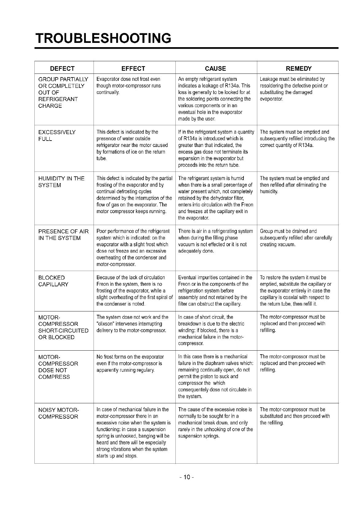
LG GR-151SF User manual

Type
User manual
SAFETY PRECAUTIONS
1. Check if an electric leakage occurs in the set.
2. When servicing current applying parts, unplug prior to
servicing.
3. In case of testing with power injecting, wear rubber
gloves to prevent electric shock.
4. If you use any appliances, check regular current, voltage
and capacity.
5. Don't touch metal products in cold freezer room with wet
hand. It may cause frostbite.
6. Prevent water flowing to electric elements in mechanical
parts.
7. When sloping the set, remove any materials on the set,
especially thin plate type(ex,: glass plates or books.).
8. When servicing evaporator part, wear cotton gloves
without fail. It is to prevent wound by sharp fin of
evaporator.
9. Leave a breakage freezing cycle to a heavy service
center. The gas in cycle inside may soil ambient air.
SERVICING PRECAUTIONS
AIR RECHARGING IN COMPRESSOR
Test the refrigeration system by connecting it electrically
before refilling operation. This is necessary to ascertain the
function of the motor-compressor and identify the defects
immediately. If the defects have been found, empty the old
system of eventual R-12 residue by breaking off the end of
the extension piece at its narrow point. (Figure 1)
Replace the filter and any damaged components. Unsolder
and pull off the piece remaining inside the service tube and
then attach an extension completely with male Hansen and
last, solder it to the same tube again. (Figure 2)
It is necessary to execute the soldering operation with
valve open so that the fumes caused by oil residue can
come out freely without blowholes between two tubes
during heating the point to be soldered.
The extension fitted with the male Hansen is connected to
the female fitting of the vacuum pump tube. (Figure 3)
Air evacuating from the system begins as soon as the
pump starts. The refrigeration system must be kept under
vacuum until the reading on the low-pressure gauge
indicates vacuum (0 absolute, -1 atm., -760 mm Hg) in any
case it is advisable to keep the pump running for about
30 minutes. (Figure 4)
POINT TO BE
BROKEN
SERVICE TUBE
EXTENSION
Figure 1
CHARGE TUBE FEMALE
EXTENSION HANSEN
MALE
HANSEN
SOLDERING
POINT
Figure 2
PRESSURE
GAUGE
Figure 3 Figure 4
-3-
In case that a considerable leakage occurs and to stop the
vacuum pump will be necessary and add a small quantity
of Freon to the system, if vacuum should not be obtained
(pressure gauge can't fall to 1 atmosphere.), start the
refrigeration unit and find the leakage with the special
leak-finder. When the defective soldering point is visible,
re-do it after opening the extension tube valve and
reestablishing the normal outside pressure inside the
group.
Because the melted alloy is sucked into the tubes and
block them, the pressure must be rebalanced when
vacuum is in the system in soldering. As soon as the
vacuum operation is over, add the quantity in grams of R-
12 to the refrigeration system. Remember that every
system has an exact quantity of R-12 with a tolerance of
+5 grams than can be added. (Figure 5)
TO THE
R-12 CYLINDER
__ TO THE
= REFRIGERATION
SYSTEM
Figure 5
Before performing this operation (if the vacuum pump and
refilling cylinder are connected), make sure that the valve
placed between the vacuum pump and refilling tube are
closed to keep the Freon for adding to the system. (Figure 6)
FILLING OR VALVE TO BE
_ CHARGE TUBE OPENED WHEN
REFILLING
TO THE TO THE
REFRIGERATION CHARGE
SYSTEM CYLINDER
TO THE VALVE TO BE
VACUUM CLOSED
PUMP AFTER VACUUM
Figure 6
In addition, check the graduated scale on the cylinder for
the quantity of R-12 to be added, for example, if we have
750 grams of Freon in the cylinder and must add 165
grams to the group, this amount will be reached when R-12
has dropped to 585 grams, remembering that the indicator
shows a lower limit of meniscus. Do this after choosing the
scale corresponding to the gas pressure different scales
reported as the same gas pressure indicated by the
pressure gauge on the top of the column.
To make R-12 flow into the system, open the valve placed
at the base of the cylinder and connected to the filling tube.
The amount of Freon cannot be added to the system all at
once because it may cause a blocking of motor-compresson
Therefore, proceed by adding original quantity of about
20-30 grams and close the valve immediately.
The pressure rises and the motor-compressor must start,
sucking the gas and making the pressure go down again.
Regulate the valve again, maintaining the same manner
until reaching the quantity of R-12 established for the
system being charged. When the system is running, the
suction pressure must be stabilized from 0.30 to 0.6
atmosphere.
-4-
AIR RECHARGING IN COMPRESSOR
Test the refrigeration system by connecting it electrically
before refilling operation. This is necessary to ascertain the
function of the motor-compressor and identify the defects
immediately. If the defects have been found, empty the old
system of eventual R134a residue by breaking off the end
of the extension piece at its narrow point. (Figure 1)
Replace the filter and any damaged components. Unsolder
and pull off the piece remaining inside the service tube and
then attach an extension completely with male Hansen and
last, solder it to the same tube again. (Figure 2)
It is necessary to execute the soldering operation with
valve open so that the fumes caused by oil residue can
come out freely without blowholes between two tubes
during heating the point to be soldered.
The extension fitted with the male Hansen is connected to
the female fitting of the vacuum pump tube. (Figure 3)
Air evacuating from the system begins as soon as the
pump starts. The refrigeration system must be kept under
vacuum until the reading on the low-pressure gauge
indicates vacuum (0 absolute, -1 atm., -760 mm Hg) in any
case it is advisable to keep the pump running for about
60 minutes. (Figure 4)
POINT TO BE
BROKEN
SERVICE TUBE
EXTENSION
Figure 1
CHARGE TUBE FEMALE
EXTENSION HANSEN
MALE
HANSEN
SOLDERING
POINT
Figure 2
MP
PRESSURE
GAUGE
Figure 3 Figure 4
-5-
In case that a considerable leakage occurs and to stop the
vacuum pump will be necessary and add a small quantity
of Freon to the system, if vacuum should not be obtained
(pressure gauge can't fall to 1 atmosphere.), start the
refrigeration unit and find the leakage with the special
leak*finder. When the defective soldering point is visible,
re*do it after opening the extension tube valve and
reestablishing the normal outside pressure inside the
group.
Because the melted alloy is sucked into the tubes and
block them, the pressure must be rebalanced when
vacuum is in the system in soldering. As soon as the
vacuum operation is over, add the quantity in grams of
R134a to the refrigeration system. Remember that every
system has an exact quantity of R134a with a tolerance of
+5 grams than can be added. (Figure 5)
TO THE
R134a CYLINDER
TO THE
REFRIGERATION
SYSTEM
Figure 5
Before performing this operation (if the vacuum pump and
refilling cylinder are connected), make sure that the valve
placed between the vacuum pump and refilling tube are
closed to keep the Freon for adding to the system. (Figure 6)
FILLING OR VALVE TO BE
_ CHARGE TUBE OPENED WHEN
REFILLING
TO THE TO THE
REFRIGERATION CHARGE
SYSTEM CYLINDER
TO THE VALVE TO BE
VACUUM CLOSED
PUMP AFTER VACUUM
Figure 6
In addition, check the graduated scale on the cylinder for
the quantity of R134a to be added, for example, if we have
750 grams of Freon in the cylinder and must add 165
grams to the group, this amount will be reached when
R134a has dropped to 585 grams, remembering that the
indicator shows a lower limit of meniscus. Do this after
choosing the scale corresponding to the gas pressure
different scales reported as the same gas pressure
indicated by the pressure gauge on the top of the column.
To make R134a flow into the system, open the valve
placed at the base of the cylinder and connected to the
filling tube. The amount of Freon cannot be added to the
system all at once because it may cause a blocking of
motor*compressor. Therefore, proceed by adding original
quantity of about 20-30 grams and close the valve
immediately.
The pressure rises and the motor*compressor must start,
sucking the gas and making the pressure go down again.
Regulate the valve again, maintaining the same manner
until reaching the quantity of R134a established for the
system being charged. When the system is running, the
suction pressure must be stabilized from 0.10 to 0.4
atmosphere.
-6-
SPECIFICATIONS
ITEMS SPECIFICATIONS
DOOR TYPE 1 DOOR
NET CAPACITY 94 l
CONDENSER TYPE WALL CONDENSER
(FLUSH BACK)
DEFROSTING SYSTEM MANUAL
TEMPERATURE CONTROL KNOB DIAL
ITEMS
INSULATION DO_OR
_ CABINET
EVAPORATOR
DIMENSION
NET WEIGHT
REFRIGERANT
VS Series
COMPRESSOR
LUBRICANT
NS Series
COMPRESSOR
SPECIFICATIONS
POLYURETHANE
POLYURETHANE
ROLL BOND TYPE
463(W)X830(H)X500(D)mm
22 Kg
R-12(67g) R-134a(60g)
HTS-150 FREOL a 22G
(200cc) (200cc)
HTS-150 FREOL a 22G
(180cc) (180cc)
PARTS IDENTIFICATION
EVAPORATOR(DoorInside)
- The heartof the refrigerator.
- It evaporates the refrigerant
fluid andthereby absorbs
heatfrom the surrounding.
ICE CUBETRAY(DoorInside)
Ice cube is easy to remove
from the tray
DRIP TRAY
Catches the water that
drips off the evaporator
when defrosting.
PLASTIC COATED
SHELVES
Have full width and can
slide out.
PVC BAR
Keeps any kinds of fruits
and vegetables.
THERMOSTAT
Regulates the operation of
the motor and controls the
temperature inside the
refrigerator.
SUPPORTER CAN
Keeps any kinds of bottles.
MAGNETIC GASKET
- Tight fitting door seal
keeps all the cooling
power locked inside,
- No hooks or latches.
NOTE : This is a basic model. The shape of refrigerator is subject to change.
-7-
DISASSEMBLY
A. DOOR
1. Loosen 3 screws holding an upper hinge to separate the
door body. (Figure 7)
Figure 7
B. THERMOSTAT
1. Pull Knob Dial,
2. Loosen 1 screw holding the case and pull it out to
remove the Therme cover. (Figure 8)
Figure 8
C. COMPRESSOR AND PTC
1. Remove Clamp, Protector Cover, Power Cord and Lead
Wire first. (Figure 10)
2. Separate OLR
3. Separate PTC.
4. Remove the Compressor Base by loosening 4 bolts fixed
to base plate of the set. (Figure 11)
Figure 10
-%
Figure 11
5. Remove the Compressor by loosening 2 earth screws
next to Compressor.
NOTE : Replace the Compressor, after peeling off
painted part of earth terminal.
• Compressor inhales the gas evaporated from Evaporator
and condenses this gas and then delivers to Condenser.
PTC is abbreviation of Positive Temperature Coefficient
and is attatched to the Compressor, and operates motor.
• OLP prevents Motor coil from being started inside
Compressor.
Do not turn the Adjust Screw of OLP in any way for
normal operation of OLR
3. Pull out thermostat in the theremostat cover, and
disconnect lead wires. (Figure 9)
NOTE : Replace a new thermostat with proper specification.
@
Figure 9
-8-
CIRCUIT DIAGRAM
4
THERMOS'[A'T
YL _ BK
GN{GN_L)t <_ BK
s_
it"__FL_REs_oR
P.T.C STARTER
YL: YELLOW
BK: BLACK
BL: BLUE
GN:GREEN
THE PLUG TYPE ON CIRCUIT DIAGRAM IS SUBJECT
TO CHANGE IN DIFFERENT LOCALITIES. J652-00041C
TROUBLESHOOTING
DEFECT EFFECT CAUSE REMEDY
GROUP PARTIALLY
OR COMPLETELY
OUT OF
REFRIGERANT
CHARGE
EXCESSIVELY
FULL
HUMIDITY IN THE
SYSTEM
PRESENCE OF AIR
IN THE SYSTEM
BLOCKED
CAPILLARY
MOTOR-
COMPRESSOR
SHORT-CIRCUITED
OR BLOCKED
MOTOR-
COMPRESSOR
DOSE NOT
COMPRESS
NOISY MOTOR-
COMPRESSOR
Evaporatordose notfrosteven
thoughmotoFcompressorruns
continually.
This defectisindicatedbythe
presenced wateroutside
refrigeratornearthe motorcaused
byformationsof ice onthe return
tube.
This defectisindicatedbythe partial
frosting ofthe evaporatorand by
continualdefrostingcycles
determinedby the interruptionof the
flow ofgas onthe evaporator.The
motorcompressorkeepsrunning.
Poorperformanceofthe refrigerant
systemwhich is indicated:onthe
evaporatorwitha slightfrostwhich
dosenot freezeand anexcessive
overheatingof thecondenserand
motor-compressor.
Becauseof thelack of circulation
Freonin the system,thereis no
frosting ofthe evaporator,while a
slightoverheatingofthe first spiralof
the condenseris noted.
The systemdose notwork andthe
"clixson" intervenesinterrupting
deliverytothe motorraompressor.
Nofrostformson the evaporator
evenifthe motor-compressoris
apparentlyrunningregulary.
Incaseof mechanicalfailurein the
motor-compressorthere in an
excessivenoisewhenthe system is
functioning:incaseasuspension
spring isunhooked,bangingwill be
heardand therewill be especially
strong vibrationswhen the system
startsup and stops,
An emptyrefrigerantsystem
indicatesaleakageof R134a This
lossis generallyto belookedfor at
the soldering pointsconnectingthe
variouscomponentsor in an
eventualhole inthe evaporator
madeby the user.
Ifinthe refrigerantsystema quantity
of R134aisintroducedwhichis
greaterthanthat indicated,the
excessgas dosenot terminate its
expansionin the evaporatorbut
proceedsintothe returntube.
The refrigerantsystemis humid
when there isa small percentageof
waterpresentwhich,notcompletely
retainedbythe dehydratorfilter,
enters into circulationwiththe Freon
andfreezes atthe capillaryexitin
the evaporator.
There isair inarefrigeratingsystem
when duringthe fillingphase
vacuum isnot effectedor it is not
adequatelydone.
Eventualimpuritiescontainedin the
Freonor inthe componentsofthe
refrigerationsystembefore
assemblyandnot retainedbythe
filter canobstructthe capillary.
Incaseof shortcircuit,the
breakdownis dueto the electric
winding:if blocked,thereis a
mechanicalfailurein the motor-
compressoE
Inthiscasethereisa mechanical
failurein the diaphramvalveswhich:
remainingcontinuallyopen, do not
permitthe pistonto suck and
compressorthe which
consequenteIydosenot circulatein
the system.
The causeofthe excessivenoise is
normailytobe soughtfor in a
mechanicalbreak down,and only
rarelyin theunhookingofone of the
suspensionsprings.
Leakagemustbeeliminated by
resolderingthe defectivepoint or
substitutingthe damaged
evaporator.
Thesystemmustbe emptiedand
subsequentlyrefilledintroducingthe
correctquantityof R134a.
Thesystemmustbe emptiedand
thenrefilledafter eliminatingthe
humidity.
Groupmustbedrainedand
subsequentlyrefilledaftercarefully
creatingvacuum.
Torestorethe systemit mustbe
emptied,substitutethe capillaryor
the evaporatorentirelyin casethe
capillaryis coaxialwith respectto
the returntube,thenrefillit.
Themotor-compressormustbe
replacedandthenproceedwith
refilling.
Themotor-comprossormustbe
replacedandthenproceedwith
refilling.
Themotor-comprossormustbe
substitutedandthenproceedwith
the refilling.
-10-
NO COOLING
The Compressor
doesn't run,
Check if the current
flows at the contacting
Poor contacting point
Replace the
Thermostat.
Check if the current flows
at the contacting point of
the starting system.
Poor contacting point
and broken
Replace the device.
Check if the current
flowing of the sub coil of _ "
-11-
COMPRESSOR AND ANOTHER ELECTRIC COMPONENTS
Separate the PTC-STARTER from
the Compressor and measure the
voltage between M and C of the
Compressor.
Equal to the applied _ r_
voltage. (Rating _ 2>
voltage + 10%) I
Check the L
resistance of the
Compressor Motor.
YES
YES
NO
NO
YES
OLP works within 30 sec.
in forcible OLP operation
by turning instant power on _ NO _
Replace OLR
Measure minimum starting voltage
after checking steps 1-3 above.
And measure the pressure balance
of the PTC with the interval of
more than 5 min.
-12-
PTC
Poor starting or no
operating of the
Compressor.
4D
First, separate the PTC from
the Compressor and check the
voltage between NO 5 and 6
in the PTC with a muititester or
Wheatstone Bridge.
F
Normal _ Check another
electric
components.
__ Abnormal _ Replace the
PTC.
_{_ Abnormal _ Replace the
PTC.
4m
Separate the OLP from
the Compressor and
check resistance value
between two terminals of
OLP with Tester.
-13-
EXPLODED VIEW
-14-
-15-
HOME DEPOT(HDP) Electrical Specification
ITEM GR-051SF GR-131SF GR=151SF
BUYER MODEL NAME GR_051SF GR_131SPF GR-151SPF
RATED INPUT(W) 70+15% 70+15% 70+15%
DEFROST INPUT(W)
ENERGY CONSUMPTION(kwh/yr) 288 330 350
AMPERE(Amp) 0.84 1.0 0.7
RATING(V/Hz) 115/60 115/60 115/60
REFRIGERANT R134a R134a R134a
CHARGE(Oz) 1.41 2.12 3.35
COMPRESSOR NS24LBCM NS24LBCG NS30LACM
OLP 4TM232NFB 4TM232NFB 4TM265MFB
PTC P6R8MD P6R8MC P6R8MD
CAPACITOR-R 101JF/250VAC 101JF/250VAC
CAPACITOR-S
  • Page 1 1
  • Page 2 2
  • Page 3 3
  • Page 4 4
  • Page 5 5
  • Page 6 6
  • Page 7 7
  • Page 8 8
  • Page 9 9
  • Page 10 10
  • Page 11 11
  • Page 12 12
  • Page 13 13
  • Page 14 14

LG GR-151SF User manual

Type
User manual

Ask a question and I''ll find the answer in the document

Finding information in a document is now easier with AI