Page is loading ...

1
MIRA SILVER
Installation and User Guide
THERMOSTATIC MIXER
These instructions must be left with the user.
For SPARES, ADVICE
or REPAIRS
Please call us on
0844 571 5000
(UK Only)

2
CONTENTS
Introduction .............................................................................................3
Guarantee ............................................................................................4
Patents and Design Registration ..........................................................4
Safety : Warnings ....................................................................................5
Pack Contents .........................................................................................7
Dimensions ..............................................................................................9
Specications ........................................................................................10
Operating Parameters ........................................................................ 10
Installation Requirements ....................................................................12
Installation .............................................................................................14
General ...............................................................................................14
Installation Methods ...........................................................................15
Exposed Thermostatic Mixer .............................................................. 16
1. Rear Entry Supplies (rising or falling concealed pipework) ............ 16
2. Rising or Falling Supplies ...............................................................18
Built-in Thermostatic Mixer ................................................................. 20
1. Solid Wall or Stud Partition
(Using Securing Brackets - Mounting on Front Face of Wall) ....20
2. Solid Wall or Stud Partition
(Using Rear Fixing Points on the Thermostatic Mixer) ...............23
3. Laminated Panel
(Using Securing Brackets - Mounting on Rear Face of Wall) ..... 25
Control Assembly (Built-in Models) .................................................... 27
Reversed Inlet Supplies ........................................................................ 28
Operation ...............................................................................................30
Commissioning .....................................................................................31
Maximum Temperature Setting .......................................................... 31
Fault Diagnosis ......................................................................................32
Maintenance ...........................................................................................33
General ...............................................................................................33
Spare Parts ............................................................................................36
Accessories ...........................................................................................38
Notes ......................................................................................................39
Customer Service .................................................................................. 40

3
INTRODUCTION
Thank you for purchasing a quality Mira product. To enjoy the full potential of your
new product, please take time to read this guide thoroughly, having done so, keep
it handy for future reference.
The Mira Silver Thermostatic Mixer is a Thermostatic Shower Control with a single
control lever for on/off and temperature control.
There is no adjustable ow control. A 12 L/Min ow regulator is supplied for high
pressure systems to reduce excessive shower force.
The Thermostatic Mixer incorporates a wax capsule temperature sensing unit, which
provides an almost immediate response to changes in pressures or temperature of
the incoming water supplies to maintain the selected temperature. An adjustable
maximum temperature stop is provided which limits the temperature to a safe level.
Inlet Filters are tted to protect the thermostatic cartridge.
Mira Silver Exposed: Thermostatic Mixer for connection to rising, falling or rear
entry pipework, supplied with L10 EV Shower Fittings.
Mira Silver Built-in: Thermostatic Mixer for connection to concealed pipework,
supplied with L10 BIV or BIR Shower Fittings.
Type 2 Valves
This product has been certied as a Type 2 valve under the BUILDCERT TMV2 scheme.
This product also complies with the Water Supply (water ttings) Regulations 1999.
Application
The approved designations for Type 2 Valves are as follows:
Model Designation
Mira Silver HP-S, LP-S
Important! The tting of any ow regulator will invalidate TMV2 compliance due to
the minimum ow rate requirements. Do not t ow regulators in TMV2 applications.
For Type 2 Valves refer to the TMV2 Requirements Manual.

4
If you experience any difculty with the installation or operation of your new
Thermostatic Mixer, please refer to ‘Fault Diagnosis’, before contacting Kohler Mira
Ltd. Our telephone and fax numbers can be found on the back cover of this guide.
Guarantee
For domestic installations, Mira Showers guarantee the Mira Silver Thermostatic
Mixer against any defect in materials or workmanship for a period of ve years from
the date of purchase.
For non-domestic installations, Mira Showers guarantee the Mira Silver
Thermostatic Mixer against any defect in materials or workmanship for a period of
ve years from the date of purchase.
For terms and conditions refer to the back cover of this guide.
Recommended Usage
Application
Domestic
ü
Light Commercial
ü
Heavy Commercial
û
Healthcare
û
Patents and Design Registration
Design Registration: 000555768-008, 000555768-009
Patents: GB: 2 291 693, 2 392 225, 2 421 297
Germany: 695 13 455.8
France: 0 694 721 (E)
USA 7 240 850
Patent Applications: GB: 0621637.8
Euro: 1 672 257, 03254070.0
USA: 2006-0124758-A1

5
SAFETY : WARNINGS
This Mira Silver Thermostatic Mixer is precision engineered and should give continued
safe and controlled performance, provided:
1. It is installed, commissioned, operated and maintained in accordance with
manufacturer’s recommendations.
2. Periodic attention is given, when necessary, to maintain the product in good
functional order.
3. Type 2 Valves are only used for applications covered by their approved
designations, refer to the TMV2 Requirements Manual.
Caution!
1. Read all of these instructions.
2. Retain this guide for later use.
3. Pass on this guide in the event of change of ownership of the installation site.
4. Follow all warnings, cautions and instructions contained in this guide.
5. The function of a thermostatic mixing valve is to deliver water consistently at a safe
temperature. In keeping with every other mechanism, it cannot be considered as
functionally infallible and as such, cannot totally replace a supervisor’s vigilance
where that is necessary. Provided it is installed, commissioned, operated and
maintained within manufacturers recommendations, the risk of failure, if not
eliminated, is reduced to the minimum achievable.
6. Anyone who may have difculty understanding or operating the controls of any
shower should be attended whilst showering. Particular consideration should
be given to the young, the elderly, the inrm or anyone inexperienced in the
correct operation of the controls. This shower is not intended for use by persons
(including children) with reduced physical, sensory or mental capabilities, or
lack of experience and knowledge, unless they have been given supervision or
instruction concerning the use of the shower by a person responsible for their
safety.
7. Rapid/Excessive movement of the ow and/or temperature control levers may
result in momentary unstable blend temperatures.
8. Care is required when adjusting ow or temperature, make sure that the
temperature has stabilised. Sunburn or skin conditions can increase your
sensitivity to hot water.
9. Make sure that you fully understand how to operate this shower and make sure
that it is properly maintained in accordance with the instructions given in this
manual.

6
10. The plumbing installation must comply with the requirements of UK Water
Regulations/Bye-laws (Scotland), Building Regulations or any particular
regulations and practices, specied by the local water supplier. The installation
should be carried out by a plumber or contractor who is registered or is
a member of an association such as:
i) Institute of Plumbing (IOP), throughout the UK.
ii) National Association of Plumbing, Heating and Mechanical Services
Contractors (NAPH & MSC), England and Wales.
iii) Scottish and Northern Ireland Plumbing Employers’ Federation
(SNIPEF), Scotland and Northern Ireland.
11. The shower head must be de-scaled regularly. Lack of regular shower head
cleaning will lead to poor performance and cause early failure of the product.
If necessary refer to the Shower Fittings User Guide for more information.
12. When this product has reached the end of its serviceable life, it should be
disposed of in a safe manner, in accordance with current local authority
recycling, or waste disposal policy.

7
PACK CONTENTS
Tick the appropriate boxes to familiarize yourself with the part names and to
conrm that the parts are included.
1 x Mira Silver Thermostatic Mixer
1 x ‘O’ Key
2 x Olives
2 x Compression
Nuts
2 x Concealing
Plates
1 x 2.5 mm
Hexagon Key
2 x No. 8 x 1 ¼”
Screws
2 x Wall Plugs
Documentation
1 x Guarantee Registration Document
1 x Installation Template
1 x TMV2 Requirements Manual
1 x 12 L/Min
Flow Regulator
Exposed Silver Thermostatic Mixer
1 x Cartridge
Removal Socket

8
Built-in Silver Thermostatic Mixer
Documentation
1 x Guarantee Registration Document
1 x TMV2 Requirements Manual
1 x 2.5 mm
Hexagon Key
2 x No. 8 x 1 ¼”
Screws
2 x Wall Plugs
1 x 12 L/Min
Flow Regulator
3 x Olives
3 x Compression
Nuts
1 x Mira Silver Thermostatic Mixer
(attached to the Building-in Shroud)
1 x Control Assembly
2 x M5 x 40 mm
Screws
2 x Securing
Brackets
1 x ‘O’ Key
2 x Bracket
Securing Screws

9
DIMENSIONS
153137
Ø70
35
Ø56
105
20
67 - 85
Building-in Depth
72 Ø183
108
All dimensions in mm.
Exposed Silver Thermostatic Mixer
Built-in Silver Thermostatic Mixer

10
Operating Parameters
For Type 2 Valves, the supply conditions specied in the TMV2 Requirements Manual
take precedence over the operating parameters which follow.
Pressures
Maximum Static Pressure: 10 Bar.
Maximum Maintained Pressure: 5 Bar.
Minimum Maintained Pressure (Gas Water Heater): 1.0 Bar.
(for optimum performance supplies should be nominally equal).
Minimum Maintained Pressure (Gravity System): 0.1 Bar.
(0.1 bar = 1 Metre head from base of cold tank to the outlet of the shower handset).
Note! For combination type boilers it may be necessary to t the ow regulator
(supplied) to restrict the ow through the boiler to ensure it produces a sufciently
hot water temperature.
Important! The tting of ow regulators will invalidate any TMV2 compliance due to the
minimum ow rate requirements. Do not t the ow regulator in TMV2 applications.
Temperatures
Factory Pre-set (Blend) Shower: 43°C.
Optimum Thermostatic Control Range: 35°C - 45°C.
(Achieved with supplies of 15°C cold, 65°C hot and nominally equal pressures).
Recommended Hot Supply: 60°C - 65°C.
Note! The Mixing Valve can operate at temperatures up to 85°C for short periods
without damage. However for safety reasons it is recommended that the maximum
hot water temperature is limited to 65°C.
Minimum Differential between Hot Supply and Outlet Temperature: 10°C.
Cold Water Range: 5°C - 25°C.
Thermostatic Shut-down
For safety the Thermostat will shut off the Hot Supply Within 2 Seconds if the Cold
Supply Fails.
(Achieved only if the hot supply temperature is greater than 10°C above the set
blend temperature).
Connections
Exposed Mixer:
Inlets: 15 mm Compression, Hot - Left, Cold - Right.
Outlet: ½” BSP Flat Face, Bottom - Outlet.
Built-in Mixer:
Inlets: 15 mm Compression, Hot - Left, Cold - Right.
Outlet: 15 mm Compression, Top - Outlet.
If reversed inlets are required refer to section: ‘Reversed Inlet Supplies’.
SPECIFICATIONS

11
Flow Rates
Typical Flow Rates on Low Pressure Systems (0.1 Bar to 1 Bar) - Mira Silver with
L10 Adjustable Fittings or Rigid Head:
Typical Flow Rates on High Pressure Systems (1 Bar to 5 Bar, with 12 Litre/Min Flow
Regulator tted in shower control outlet) - Mira Silver with L10 Adjustable Fittings
or Rigid Head:
Flow Regulator Installation
Flow regulators are supplied with this product and should be tted in high pressure
systems to either;
1. Reduce Excessive Force & Flow Rate
2. Reduce Noise through the mixer due to high or unequal pressures
3. Stabilise incoming supply temperatures
Important! The tting of any ow regulator will invalidate TMV2 compliance due to
the minimum ow rate requirements. Do not t ow regulators in TMV2 applications.

12
INSTALLATION REQUIREMENTS
Isolating Valve
Thermostatic Mixer
Overow Indicator
Pressure Reducing Valve
Float Valve
Twin Impeller Pump
Single Impeller Pump
Tempering Valve
Mini Expansion Vessel
Key to Symbols
The Mira Silver Thermostatic Mixer is compatible with the following systems:
Gravity fed system
The Thermostatic Mixer MUST be fed from
a cold water cistern and hot water cylinder
providing nominally equal pressure.
Gas heated system
The Thermostatic Mixer MUST be installed
with a gas water heater or combination
boiler of a fully modulating design.
Note! We recommend the use of a
12 L/Min Outlet Flow Regulator (supplied).
However, it is possible following the
installation of the Flow Regulator that the
ow rate is reduced too much for the boiler
to ignite. If this is the case remove the ow
regulator.

13
Unvented mains pressure system
The Thermostatic Mixer can be installed
with a unvented, stored hot water
cylinder.
Note! We recommend the use of a 12 L/Min
Outlet Flow Regulator (supplied).
Mains pressurised instantaneous hot
water system (thermal store)
The Thermostatic Mixer can be installed
with systems of this type with balanced
pressures.
Note! We recommend the use of a 12 L/Min
Outlet Flow Regulator (supplied).
Pumped system
The Thermostatic Mixer can be installed
with an inlet pump (twin impeller). The pump
must be installed on the oor next to the hot
water cylinder.
Note! We recommend the
use of a 12 L/Min Outlet
Flow Regulator (supplied).
Air Separation
30°-60°
90°

14
INSTALLATION
General
Installation must be carried out in accordance with these instructions, and must be
conducted by designated, qualied and competent personnel.
The installation must comply with the “Water Supply Regulations 1999 (Water Fittings)”
or any particular regulations and practices, specied by the local water company or
water undertakers.
Note! Make sure that all site requirements correspond to the information given in
section: ‘Specications’. For Type 2 Valves see also supply conditions in the TMV2
Requirements Manual.
1. The Mixer must not be installed in an area where it may freeze.
2. For stud partitions alternative xings may be required.
3. Isolating valves must be installed close to the Mixer for ease of maintenance.
4. Pipework must be rigidly supported and avoid any strain on the connections.
5. Pipework dead-legs should be kept to a minimum.
6. Supply pipework layout should be arranged to minimise the effect of other outlet
usage upon the dynamic pressures at the Mixer inlets.
7. Inlet and outlet threaded joint connections should be made with PTFE tape or
liquid sealant. Do not use oil-based, non-setting joint compounds.
8. To eliminate pipe debris it is essential that supply pipes are thoroughly ushed
through before nal connection.
9. Decide on a suitable position for the
Mixer. The position of the Mixer and
the Shower Fittings must provide
a minimum gap of 25 mm between
the spill-over level of the shower
tray/bath and the handset. This is to
prevent back-siphonage. For further
information on the installation of your
Shower Fittings, refer to the Fittings
Installation and User Guide.
Note! Only use Shower Fittings
recommended by the manufacturer
or supplier.
25 mm
Spill Over
Level
Hose Retaining Ring

15
Installation Methods
Exposed Silver Thermostatic Mixer
The Exposed Silver Mixer can be installed
with rear, rising or falling supply inlets.
For rear entry supplies, go to section:
‘Exposed Thermostatic Mixer, 1. Rear
Entry Supplies’.
For rising or falling supplies, go to section:
‘Exposed Thermostatic Mixer, 2. Rising
or Falling Supplies’.
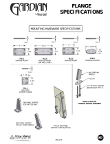
Built-in Silver Thermostatic Mixer
The Built-in Silver Mixer can be installed
with rising or falling supply inlets (rising
inlets are illustrated).
The Mixer can be installed using Rear
Fixing Points on the Body, or by using the
Securing Brackets (supplied) on the Front
Face of a Solid Wall or Stud Partition, or on
the Rear Face of a Laminated Panel.
For installation into a Solid Wall or Stud
Partition using the Securing Brackets, go
to section: ‘Built-in Thermostatic Mixer,
1. Solid Wall or Stud Partition (Using
Securing Brackets - Mounting on Front
Face of Wall)’.
For installation into a Solid Wall or Stud
Partition using the Rear Fixing Points, go
to section: ‘Built-in Thermostatic Mixer,
2. Solid Wall or Stud Partition (Using
Rear Fixing Points on Thermostatic
Mixer)’.
For installation behind a Laminated
Panel using the Securing Brackets, go to
section: ‘Built-in Thermostatic Mixer,
3. Laminated Panel (Using Securing
Brackets - Mounting on Rear Face of
Wall)’.
Rear Entry Supplies
Rising or Falling Supplies
Securing Brackets
(Mounting on Front
Face of Wall)
Mounting using
Rear Fixing Points
Securing Brackets
(Mounting on Rear
Face of Wall)

16
1.1 Use the Installation Template to mark the positions of the holes for the Backplate
and the pipe centres.
Note! Allow a minimum of 150 mm either side of the Mixer, to allow access to
the hot and cold Inlet Filters for servicing.
Exposed Thermostatic Mixer
1. Rear Entry Supplies (rising or falling concealed pipework)
Ø32 mm x 10 mm depth
for Concealing Plates
153 mm
Apply Silicone
Sealant
Backplate
Concealing Plates
10 mm minimum
between Elbow
and nished wall
surface
32 mm
18 mm from
nished wall
surface
Elbow
1.2 For solid walls drill the holes for the Backplate with a 6 mm drill and insert the
Wall Plugs (supplied). For other types of wall structure alternative xings may
be required (not supplied).
1.3 Drill the holes for the supply pipes at 153 mm centres.
1.4 Recess the wall to allow for the Concealing Plates, Ø 32 mm x 10 mm deep.
Note! Depth must be sufcient to prevent the Concealing Plates fouling on the
plumbing Elbows.
1.5 Fit the supply pipework (Hot - Left, Cold - Right). The pipework must project
18 mm from the nished wall surface at 153 mm centres (use the Installation
Template as a guide).
Note! If the connections are reversed, complete the installation then refer to
section: ‘Reversed Inlet Supplies’ before commissioning.
Hot
Cold
40 mm
153 mm
Shower Control
Backplate Fixing Points
(Ø6 mm)
Bend tabs inwards
Use as a support for the spirit level
Bend tabs inwards
Use as a support for the spirit level
Hot Supply Inlet
(Ø15 mm)
Make sure that supply pipes are thoroughly flushed through
before connection to the shower control
Cold Supply Inlet
(Ø15 mm)
153 mm
150 mm
40 mm
150 mm

17
1.6 Loosen the Grubscrew with the 2.5 mm Hexagon Key (supplied) and remove
the Backplate from the Mixer.
1.7 Secure the Backplate to the wall using the Screws (supplied).
1.8 Fit the Concealing Plates.
Note! Apply silicone sealant to the back face of the ange.
Caution! It is essential at this point that the supply pipework is thoroughly
ushed through before connection to the Mixer. Failure to do so may result in
product malfunction.
1.9 Fit the Compression Nuts and Olives onto the pipework.
1.10 Align the Mixer with the pipework and t onto the Backplate.
1.11 Tighten the Compression Nuts onto the Mixer with a suitable Spanner.
Caution! Take care not to damage the chrome surfaces.
1.12 Tighten the Grubscrew to secure the Mixer to the Backplate.
1.13 Fit the Shower Fittings, refer to your Shower Fittings Installation and User
Guide for Instructions.
Note! For high pressure systems, a 12 litre/minute Flow Regulator (supplied)
can be tted under the Hose Washer (refer to illustration).
Important! The tting of this ow regulator will invalidate any TMV2 compliance
due to the minimum ow rate requirements. Do not t the ow regulator in TMV2
applications.
1.14 Turn on the hot and cold water supplies and check for leaks.
1.15 Before using the Shower, refer to section: ‘Commissioning’.
Flow regulator
(for high pressure
systems)
Grubscrew
Hot
Cold

18
2. Rising or Falling Supplies
2.1 Loosen the Grubscrew on each
Elbow using the 2.5 mm Hexagon
Key (supplied) and rotate the Elbow
90° as required. Retighten the
Grubscrews.
2.2 Use the Installation Template to mark
the positions of the xing holes for the
Backplate.
Note! Allow a minimum of 150 mm
either side of the Mixer, to allow
access to the hot and cold Inlet Filters
for servicing.
Wall Plugs
40 mm
153 mm
Shower Control
Backplate Fixing Points
(Ø6 mm)
Bend tabs inwards
Use as a support for the spirit level
Bend tabs inwards
Use as a support for the spirit level
Hot Supply Inlet
(Ø15 mm)
Make sure that supply pipes are thoroughly flushed through
before connection to the shower control
Cold Supply Inlet
(Ø15 mm)
153 mm
150 mm 150 mm
40 mm
35 mm
35 mm
35 mm
2.3 For solid walls drill the holes for
the Backplate with a 6 mm drill and
insert the Wall Plugs (supplied).
For other types of wall structure
alternative xings may be required
(not supplied).
2.4 For Falling Supplies: Using the
Installation Template as a guide,
mark the pipe positions on the ceiling
and set the 35 mm centres from the
nished wall (refer to illustration).
For Rising Supplies: Using the
Installation Template as a guide,
mark the pipe positions and set the
35 mm centres from the finished
wall.
153 mm

19
2.5 Fit the supply pipework (Hot - Left,
Cold - Right).
Note! If the connections are reversed,
complete the installation then refer to
section: ‘Reversed Inlet Supplies’
before commissioning.
2.6 Loosen the Grubscrew with the
2.5 mm Hexagon Key (supplied)
and remove the Backplate from the
Mixer.
2.7 Secure the Backplate to the wall
using the Screws (supplied).
Caution! It is essential at this point
that the supply pipework is thoroughly
ushed through before connection to
the Mixer. Failure to do so may result
in product malfunction.
2.8 Fit the Compression Nuts and Olives
onto the pipework.
2.9 Align the Mixer with the pipework and
t onto the Backplate.
2.10 Tighten the Compression Nuts onto
the Mixer with a suitable Spanner.
Caution! Take care not to damage
the chrome surfaces.
2.11 Tighten the Grubscrew to secure the
Mixer to the Backplate.
2.12 Fit the Shower Fittings, refer to your
Shower Fittings Installation and User
Guide for Instructions.
Note! For high pressure systems,
a 12 litre/minute Flow Regulator
(supplied) can be tted under the
Hose Washer (refer to illustration).
Important! The tting of this ow
regulator will invalidate any TMV2
compliance due to the minimum ow
rate requirements. Do not t the ow
regulator in TMV2 applications.
2.13 Turn on the hot and cold water
supplies and check for leaks.
2.14 Before using the Shower, refer to
section: ‘Commissioning’.
Flow regulator
(for high pressure
systems)
Grubscrew
Hot
Cold

20
Built-in Thermostatic Mixer
1. Solid Wall or Stud Partition
(Using Securing Brackets - Mounting on Front Face of Wall)
1.1 Determine the route for the hot and
cold supply pipework and for the
outlet pipework. When connecting
to the BIV Shower Fittings it is
recommended that the outlet be
positioned above and to one side
of the Mixer. This is to prevent the
Flexible Hose from obstructing the
Shower Controls.
1.2 Remove the two Shroud Screws
(retain for later use) and remove the
Mixer from the Building-in Shroud.
1.3 Determine the position of the Mixer
and draw around the Building-in
Shroud.
1.4 Mark the routes for the hot and cold
supply pipework at 108 mm centres
(Hot - Left, Cold - Right).
Falling Supplies: For falling supplies
use the 2.5 mm hexagonal key
(supplied) to loosen the grubscrew
in each elbow.
Note! It is important to retract the
grubscrews sufciently to clear the
‘O’ seals and the inlet ange to avoid
causing damage to the seals.
1.5 Remove the elbows and install on
opposite sides. Make sure that the
elbows are pushed fully onto the inlet
stubs then retighten the grubscrews
using the 2.5 mm hexagonal key.
Caution! Do not overtighten.
Note! Make sure that the ‘O’ Seals
are correctly tted and that the Filter
Plugs are positioned to the front
(i.e. Hexagonal Key facing forward).
1.6 Mark the route for the outlet pipework.
Note! The Outlet Elbow should be
sited above the Mixer and on the right
or left, as site dictates.
Outlet Pipe BIR
Outlet Pipe BIV Outlet Pipe BIV
Cold InletHot Inlet
Thermostatic
Mixer
Alternative Pipe
Layouts
62 mm Min
24 mm Max
Finished Wall
6 mm Min
Finished Wall
Finished Wall
Surface
Securing
Bracket
/