
WARNING: This product contains chemicals known to the State of
California to cause cancer and birth defects or other reproductive harm.
For more information: Watts.com/prop65
306P
_
D - 02/20 12 of 12 © 2020 tekmar
Tel: (250) 545-7749 • Fax: (250) 984-0815
tekmarControls.com
All specications are subject to change without notice
Limited Warranty The liability of tekmar under this warranty is limited. The
Purchaser, by taking receipt of any tekmar product (“Product”), acknowl-
edges the terms of the Limited Warranty in effect at the time of such Product
sale and acknowledges that it has read and understands same.
The tekmar Limited Warranty to the Purchaser on the Products sold hereunder
is a manufacturer’s pass-through warranty which the Purchaser is authorized to
pass through to its customers. Under the Limited Warranty, each tekmar Prod-
uct is warranted against defects in workmanship and materials if the Product
is installed and used in compliance with tekmar’s instructions, ordinary wear
and tear excepted. The pass-through warranty period is for a period of twen-
ty-four (24) months from the production date if the Product is not installed during
that period, or twelve (12) months from the documented date of installation if
installed within twenty-four (24) months from the production date.
The liability of tekmar under the Limited Warranty shall be limited to, at tekmar’s
sole discretion: the cost of parts and labor provided by tekmar to repair defects in
materials and / or workmanship of the defective product; or to the exchange of the
defective product for a warranty replacement product; or to the granting of credit
limited to the original cost of the defective product, and such repair, exchange or
credit shall be the sole remedy available from tekmar, and, without limiting the
foregoing in any way, tekmar is not responsible, in contract, tort or strict prod-
uct liability, for any other losses, costs, expenses, inconveniences, or damages,
whether direct, indirect, special, secondary, incidental or consequential, arising
from ownership or use of the product, or from defects in workmanship or materials,
including any liability for fundamental breach of contract.
The pass-through Limited Warranty applies only to those defective Products
returned to tekmar during the warranty period. This Limited Warranty does not
cover the cost of the parts or labor to remove or transport the defective Product, or
to reinstall the repaired or replacement Product, all such costs and expenses being
subject to Purchaser’s agreement and warranty with its customers.
Any representations or warranties about the Products made by Purchaser to its cus-
tomers which are different from or in excess of the tekmar Limited Warranty are the
Purchaser’s sole responsibility and obligation. Purchaser shall indemnify and hold
tekmar harmless from and against any and all claims, liabilities and damages of any
kind or nature which arise out of or are related to any such representations or war-
ranties by Purchaser to its customers.
The pass-through Limited Warranty does not apply if the returned Product has been
damaged by negligence by persons other than tekmar, accident, fire, Act of God,
abuse or misuse; or has been damaged by modifications, alterations or attachments
made subsequent to purchase which have not been authorized by tekmar; or if the
Product was not installed in compliance with tekmar’s instructions and / or the local
codes and ordinances; or if due to defective installation of the Product; or if the Prod-
uct was not used in compliance with tekmar’s instructions.
THIS WARRANTY IS IN LIEU OF ALL OTHER WARRANTIES, EXPRESS OR
IMPLIED, WHICH THE GOVERNING LAW ALLOWS PARTIES TO CONTRACTU-
ALLY EXCLUDE, INCLUDING, WITHOUT LIMITATION, IMPLIED WARRANTIES
OF MERCHANTABILITY AND FITNESS FOR A PARTICULAR PURPOSE, DURA-
BILITY OR DESCRIPTION OF THE PRODUCT, ITS NON-INFRINGEMENT OF
ANY RELEVANT PATENTS OR TRADEMARKS, AND ITS COMPLIANCE WITH
OR NON-VIOLATION OF ANY APPLICABLE ENVIRONMENTAL, HEALTH OR
SAFETY LEGISLATION; THE TERM OF ANY OTHER WARRANTY NOT HEREBY
CONTRACTUALLY EXCLUDED IS LIMITED SUCH THAT IT SHALL NOT EXTEND
BEYOND TWENTY-FOUR (24) MONTHS FROM THE PRODUCTION DATE, TO
THE EXTENT THAT SUCH LIMITATION IS ALLOWED BY THE GOVERNING LAW.
Product Warranty Return Procedure All Products that are believed to have
defects in workmanship or materials must be returned, together with a written
description of the defect, to the tekmar Representative assigned to the territory in
which such Product is located. If tekmar receives an inquiry from someone other
than a tekmar Representative, including an inquiry from Purchaser (if not a tekmar
Representative) or Purchaser’s customers, regarding a potential warranty claim,
tekmar’s sole obligation shall be to provide the address and other contact informa-
tion regarding the appropriate Representative.
Limited Warranty and Product Return Procedure
Technical Data
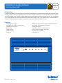
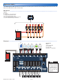
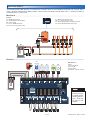
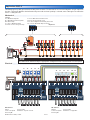
Switching Relay 306P Six Zones with Priority
Literature 306P_C, 306P_D, 306_J
Control Microprocessor control. This is not a safety (limit) control.
Packaged weight 5.0 lb. (2250 g)
Dimensions 8-3/16" H x 10-02/20" W x 2-3/8" D (208 x 271 x 60 mm)
Enclosure Cover: ABS plastic, Base: galvanized steel, NEMA type 1
Approvals
CSA C US
Ambient conditions 32 to 122°F (0 to 50°C), ≤ 90% RH non-condensing
Power supply 115 V (ac) ±10%, 60 Hz, 17.3 A
Transformer 40 VA at 24 V (ac), expandable to 80 VA with additional transformer M3069 (sold separately)
Control load 7 VA at 24 V (ac)
Fuses T5A 250 V slow blow, two spare fuses included
Pump relays 115 V (ac), 5 A, 1/3 hp, 17.3 A combined
Boiler XX end switch 24 V (ac), 5 A
DHW end switch 24 V (ac), 5 A
Mod boiler output 0-10 V (dc) 500 Ω min impedance / 4-20 mA 1 kΩ max impedance


 1
1
 2
2
 3
3
 4
4
 5
5
 6
6
 7
7
 8
8
 9
9
 10
10
 11
11
 12
12


tekmar Wall Trim Plate 014 Installation guide
Watts 306P Installation guide
Viessmann ViCare Installation guide
Tekmar Control Systems 304V Installation guide
Rehau Deluxe Operating instructions
Lochinvar Condensing Boiler User manual
Laars MFTHW140NA1XN User guide