BBV28587 02/2012 17
Thermal resistances and losses
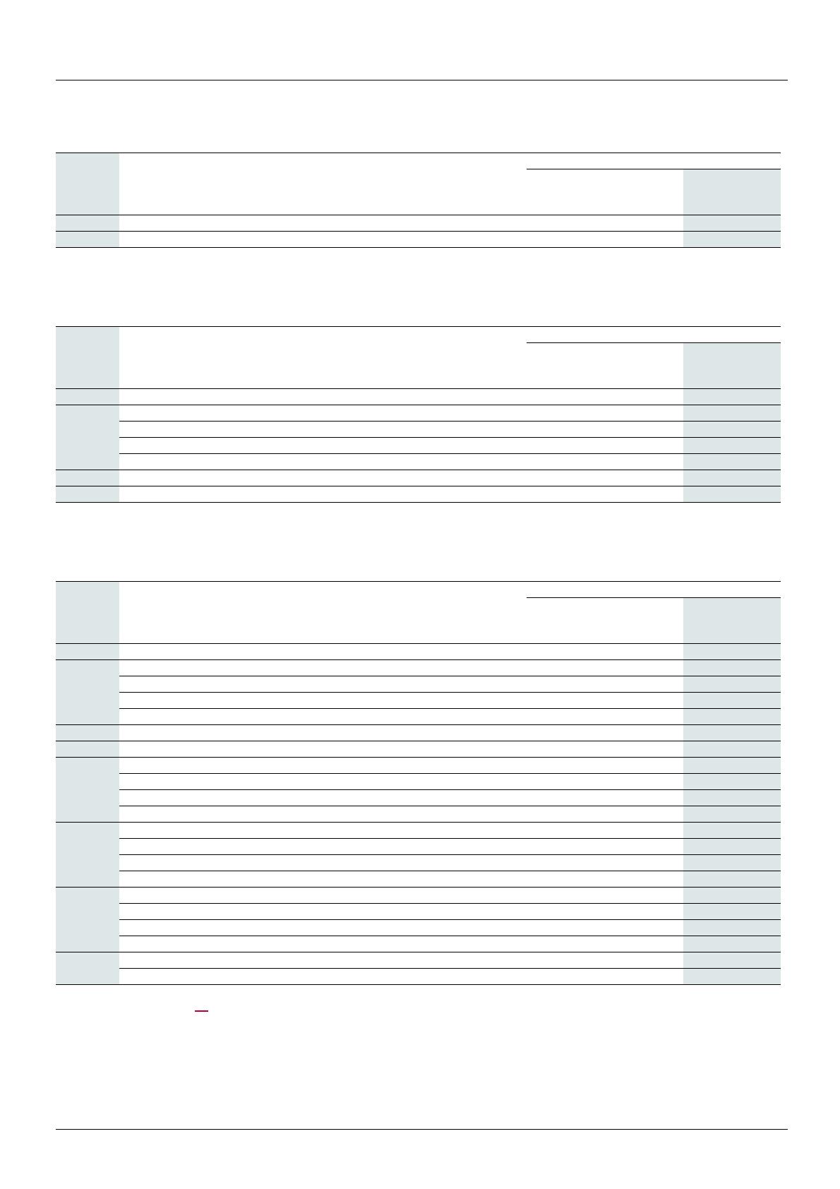
Single-phase supply voltage: 100…120 V 50/60 Hz
Single-phase supply voltage: 200…240 V 50/60 Hz
Three-phase supply voltage: 200…240 V 50/60 Hz
(1)See definition on page 15. The table takes into account a 10% margin.
(2) K/W: kelvin per watt
(3)Concentrated heatsource
(4)These losses take into account the derating used for switching frequency.
Drive Frequency Thermal
losses
(4) L
OAD
Thermal
density
Concentrated heatsource
surface area
Thermal resistance R
th
(1)
baseplate
R
BP
grease
R
G
External
heatsink R
Ext
(3)
ATV12P kHz W W/m² (W/sqft) mm (in.) K/W (2) K/W (2) K/W (2)
037F1 4 to 16 17 1816 (169) 72 x 130 (2.83 x 5.12) 0,04 0,012 2,6
Drive Frequency Thermal
losses
(4) L
OAD
Thermal
density
Concentrated heatsource
surface area
Thermal resistance R
th
(1)
baseplate
R
BP
grease
R
G
External
heatsink R
Ext
(3)
ATV12P kHz W W/m² (W/sqft) mm (in.) K/W (2) K/W (2) K/W (2)
037M2
4 16 1709 (159) 72 x 130 (2.83 x 5.12) 0,04 0,012
2,75
8 17 1816 (169) 72 x 130 (2.83 x 5.12) 0,04 0,012
2,6
12 18 1923 (179) 72 x 130 (2.83 x 5.12) 0,04 0,012
2,45
16 18 1923 (179) 72 x 130 (2.83 x 5.12) 0,04 0,012
2,45
055M2 4 to 16 24 2564 (238) 72 x 130 (2.83 x 5.12) 0,04 0,012 1.82
075M2 4 to 16 31 3312 (308) 72 x 130 (2.83 x 5.12) 0,04 0,012 1.4
Drive Frequency Thermal
losses
(4) L
OAD
Thermal
density
Concentrated heatsource
surface area
Thermal resistance R
th
(1)
baseplate
R
BP
grease
R
G
External
heatsink R
Ext
(3)
ATV12P kHz W W/m² (W/sqft) mm (in.) K/W (2) K/W (2) K/W (2)
037M3
4 14 1496 (139) 72 x 130 (2.83 x 5.12) 0,04 0,012
3,16
8 15 1603 (149) 72 x 130 (2.83 x 5.12) 0,04 0,012
2,95
12 16 1709 (159) 72 x 130 (2.83 x 5.12) 0,04 0,012
2,76
16 16 1709 (159) 72 x 130 (2.83 x 5.12) 0,04 0,012
2,76
055M3 4 23 2457 (228) 72 x 130 (2.83 x 5.12) 0,04 0,012 1.9
075M3 4 to 16 29 3098 (288) 72 x 130 (2.83 x 5.12) 0,04 0,012 1.5
U15M3
4 57 4176 (388) 72 x 130 (2.83 x 5.12) 0,012 0,008
0,77
8 64 4689 (436) 72 x 130 (2.83 x 5.12) 0,012 0,008
0,68
12 69 5055 (470) 72 x 130 (2.83 x 5.12) 0,012 0,008
0,63
16 71 5201 (483) 72 x 130 (2.83 x 5.12) 0,012 0,008
0,61
U22M3
4 61 4469 (415) 72 x 130 (2.83 x 5.12) 0,012 0,008
0,71
8 62 4542 (422) 72 x 130 (2.83 x 5.12) 0,012 0,008
0,7
12 63 4615 (429) 72 x 130 (2.83 x 5.12) 0,012 0,008
0,69
16 63 4615 (429) 72 x 130 (2.83 x 5.12) 0,012 0,008
0,69
U30M3
4 72 3025 (281) 140 x 170 (5.51 x 6.69) 0,004 0,0036
0,61
8 74 3109 (289) 140 x 170 (5.51 x 6.69) 0,004 0,0036
0,6
12 75 3151 (293) 140 x 170 (5.51 x 6.69) 0,004 0,0036
0,59
16 75 3151 (293) 140 x 170 (5.51 x 6.69) 0,004 0,0036
0,59
U40M3
4 103 4328 (402) 140 x 170 (5.51 x 6.69) 0,004 0,0036
0,43
8 to 16 110 4622 (429) 140 x 170 (5.51 x 6.69) 0,004 0,0036
0,4


