
2 Unit Connection
On test stand left side, ensure that all 5 barb ttings are in
place & straight before connecting cylinder holder or
another test stand.
Press 2 units together until barb ttings are fully inserted &
ange screw holes align.
Insert 3 screws: to connect multiple test stands, remove
white gas plugs from all units except farthest right test stand.
Continue adding test stands to right, cylinder holders to left.*
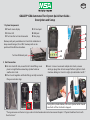
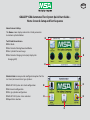
GALAXY® GX2 Automated Test System Quick Start Guide -
Description and Setup
Memory card port provided on test stand is for calibration &
bump record storage; SD or SDHC memory card can be
purchased from MSA or elsewhere.
Test stand Ethernet jacks
1 System Components
Touch screen display
Status LED
Test stand to test stand connector
SD card port
USB port
Gas plugs
If using MSA cylinder holders, left-most cylinder holder should
have fresh air lter attached to top port.
*If using ammonia or chlorine test gas, read restriction found under instruction manual chapter 2.8 “Special Conditions for Use with
Reactive Gases” .
GB/EN

ID 0818-25-MC / Sept 2012
© MSA 2012 Printed in U.S.A. Rev. 0 218 10127112
View complete product literature on the enclosed CD or visit MSAsafety.com
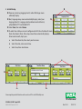
3 Initial Startup
Power on system by plugging into A/C outlet. MSA logo screen
will briey display.
Next, language setup screen automatically displays; select your
language from list. Language selection determines date format,
either MM/DD/YYYY or DD/MM/YYYY.
Select Save, then select Home.
To select time & date, users must congure each of 3 tabs at bottom of screen
(Date, Time Zone & Time). Date setup screen then automatically displays.
Enter current month, day & year.
a. Select Time Zone tab, then select your time zone.
b. Select Time tab, enter current time.
c. Select Save, then select Home.
4a.
4c.
4b.

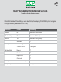
GALAXY® GX2 Automated Test System Quick Start Guide -
Test Stand Default Parameters
Refer to the listing below for for each display screen's default settings for conguring the GALAXY GX2 System. Settings can
be changed for optimal performance in the user’s facility.
Screen Name Parameter Default Setting
Date Setup Date Current date set during assembly
Time Zone Setup Time zone Eastern Time (US & Canada)
Time Setup Time Current time set during assembly
24 hour time O
Test Setup Allow simulant gas Yes for all
% volume to 100% LEL US setting for all
Test Setup - Mode Bump only O
Calibration only O
Bump/cal on fail On
Classic mode O
Test Setup- Calibration Calibration interval (days) 30
Security Setup Passcode 0000 (o)
GB/EN

ID 0818-25-MC / Sept 2012
© MSA 2012 Printed in U.S.A.
View complete product literature on the enclosed CD or visit MSAsafety.com
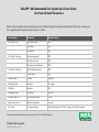
Screen Name Parameter Default Setting
GX2 Setup GX2 USB drive enable On
Display psi On
Display bar O
GX2 Setup Datalog Download periodic O
Download session O
Erase download afterward O
GX2 Setup Printing Print calibration sticker O
Print receipt O
Volume Setup Volume Medium
Backlight Setup Intensity Very high
USB Drive Enabled On
Language Setup Language English
Cylinder Setup 1 4 Auto cylinder enable All on
Expiration Setup 1 4 Weeks to expiration 4 weeks
LEL Setup % volume setting All combustible gas 100% LEL volumes set to ANSI standards
GALAXY® GX2 Automated Test System Quick Start Guide -
Test Stand Default Parameters
Refer to the listing below for for each display screen's default settings for conguring the GALAXY GX2 System. Settings can
be changed for optimal performance in the user’s facility.

GALAXY® GX2 Automated Test System Quick Start Guide -
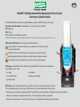
Electronic Cylinder Holder
For full functionality of electronic cylinder holder, cylinders with RFID tags must be used.
Electronic cylinder holder accommodates 1 test gas cylinder & includes:
Light band
RFID tag
Internal pressure regulator & sensor
See Galaxy GX2 Automated Test System Quick Start Guide 1 for directions regarding test stand/cylinder holder setup.
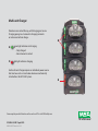
Multi-color light band indicates gas cylinder functionality:
Green indicates functional cylinder; gas parameters are within pressure &
expiration date limits.
Yellow indicates low calibration gas, or that gas nears expiration date.
Blinking yellow light band indicates cylinder holder hardware problem.
Red indicates empty calibration gas cylinder, or that gas has expired.
RFID tag gas identication reads MSA test gas cylinder RFID tag & transmits information
listed below to test stand:
• Gas type • Lot number
• Gas concentration • Cylinder part number
• Expiration date
RFID tag is only available on MSA test gas cylinders shown in manual maintenance section.
Pressure regulator & sensor read gas cylinder pressure & transmit information to test stand:
• When gas pressure drops to approximately 99 psi (6.89 bar), warning displays & display numbers appear yellow.
• When pressure drops to approximately 49 psi (3.45 bar), display numbers appear red.
• When pressure drops to less than 5 psi (0.34 bar), test stand prohibits testing using that cylinder.
GB/EN

ID 0818-25-MC / Sept 2012
© MSA 2012 Printed in U.S.A.
View complete product literature on the enclosed CD or visit MSAsafety.com
Detectors are inserted face up, with charging pins to rear.
Charging prongs must connect to charging terminals
or instrument will not charge.
Green light indicates not charging.
- Fully charged
- No instrument inserted
Red light indicates charging.
Each multi-unit charger requires an individual power source.
Unit can be used as a stand-alone device or mechanically
attached to a GALAXY GX2 System.
Multi-unit Charger

GALAXY® GX2 Automated Test System Quick Start Guide -
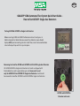
How to Test ALTAIR® Single-Gas Detectors
Testing ALTAIR & ALTAIR Pro Single-Gas Detectors
Before inserting ALTAIR or ALTAIR Pro Detector into test stand, press &
hold instrument test button for one second. Gas detector screen should
display GAS? prior to inserting into test stand. Then, insert instrument bottom
into cradle & push top until it snaps into place.
Removing Gas Seal for ALTAIR and ALTAIR Pro H2S & CO Single-Gas Detectors
All ALTAIR/ALTAIR Pro Single-Gas Detector test stands are shipped with
black rubber base seal & green rubber gas seal. Green seal is used
only for ALTAIR H2S and ALTAIR CO Single-Gas Detectors. Seal should
be removed & stored for ALTAIR O2 and all ALTAIR Pro Single-Gas Detectors.
ALTAIR and ALTAIR Pro
Detector inlet seals
GB/EN

ID 0818-25-MC / Sept 2012
© MSA 2012 Printed in U.S.A.
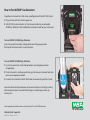
To insert ALTAIR 5/5X Multigas Detectors:
1 Insert instrument into cradle, sliding bottom over charging connector
(if applicable).
2 Pivot instrument in cradle upwards into gas inlet sleeve; instrument locks into
place once properly positioned.
3 Ensure that instrument red LEDs ash when communicating with test stand.
Several seconds will elapse between instrument insertion & start of gas testing
while communications are established. Progress screen displays when gas
testing starts.
How to Test ALTAIR® Gas Detectors
To perform instrument tests after setup & conguration of GALAXY GX2 System:
1 Plug-in Galaxy GX2 test stand to power on.
2 GALAXY GX2 System includes 1 of 3 instrument cradles to accommodate
ALTAIR Gas Detectors. Please follow the instructions listed for your instrument.
View complete product literature on the enclosed CD or visit MSAsafety.com
To insert ALTAIR 4/4X Multigas Detectors:
Insert instrument into cradle, sliding bottom over charging connector.
Push top of instrument until it snaps into place.

GALAXY® GX2 Automated Test System Quick Start Guide -
Home Screen & Setup and Test Sequence
Home Screen & Setup
The Home screen displays relevant test stand parameters
& electronic cylinder holders.
Test Stand Home Screen
Test Mode
Gas Detector Datalog Download Mode
Gas Cylinder Pressure Gauge
Gas Detector Charging status (only displays for
changing GX2)
Administrator screen provides conguration options for the
test stand, instrument & test gas cylinders:
GALAXY GX2 System test stand conguration
Instrument conguration
Test gas cylinder conguration
GALAXY GX2 System status selection
Export data selection
GB/EN

ID 0818-25-MC / Sept 2012
© MSA 2012 Printed in U.S.A.
View complete product literature on the enclosed CD or visit MSAsafety.com
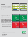
Test Sequence
Insert instrument into test stand. Several seconds
after initial IR communications, Bump or Calibration
progress screen displays include up to 6 gas
types & progress bar.
For Bump progress screen, hourglass symbol
displays in each sensor box until that sensor's
bump is complete. Green checkmark (3) or red X (x)
displa
ys f
or each sensor when bump test is complete.
Instrument Pass or Fail screen displays until a new
instrument is inserted or user makes another selection
on touch screen. If datalog downloads are enabled,
screen indicates download status (successful or failed)
at data transfer completion.
• If instrument passes test, remove it or select Home.
• If instrument fails the test, select Calibration Details
or Bump Details for sensor failure information.
-
 1
1
-
 2
2
-
 3
3
-
 4
4
-
 5
5
-
 6
6
-
 7
7
-
 8
8
-
 9
9
-
 10
10


Galaxy galaxy GX2 Quick start guide
- Type
- Quick start guide
- This manual is also suitable for
Ask a question and I''ll find the answer in the document
Finding information in a document is now easier with AI
Related papers
Other documents
-
Altair ALTAIR 5X Owner's manual
-
-
-
-
Motorola GX2-PSDC10D-R Operating instructions
-
-
MSA ALTAIR 5X IR Operating instructions
-
-
-
Turbo Chef Technologies FSB10036 User manual