MARTINDALE IN2101 Insulation & Continuity Tester 500V User manual
- Category
- Cable network testers
- Type
- User manual
This manual is also suitable for

IN2101 / IN2102
INSULATION TESTER
INSTRUCTION
MANUAL
ALWAYS READ THESE INSTRUCTIONS BEFORE PROCEEDING
Thank you for buying one of our products. For safety and a full understanding of its benefits
please read this manual before use. Technical support is available from 01923 441717 and
support@martindale-electric.co.uk
CONTENTS
1 Safety Information 1
1.1 Meaning of Symbols and Markings 1
1.2 Precautions 2
2 Introduction 4
2.1 Inspection 4
2.2 Description 4
2.3 Accessories 5
2.4 Battery Installation 5
3 Operation 5
3.1 General 5
3.2 Low Battery Indication 5
3.3 Defective Fuse Indication 6
3.4 Description of Insulation Tester Elements 6
3.5 Description of Press Buttons 6
3.6 Description of LCD Symbols 7
3.7 Battery Check 7
3.8 Auto Power Off 7
3.9 Display Auto Hold 7
3.10 Display Backlight 8
3.11 Turning the Buzzer Off 8
3.12 Zero Function 8
3.13 Locking the Test Button 9
3.14 Use of the TL47 Test Leads 9
3.15 Voltage Measurements 9
3.16 Insulation Resistance Measurements 10
3.17 Continuity Measurements 11
3.18 Resistance Measurements 12
3.19 Resistance Measurements with Buzzer 12
4 Maintenance 13
4.1 Battery Replacement 13
4.2 Fuse Replacement 13
4.3 Test Lead Replacement 14
4.4 Calibration 14
4.5 Cleaning 14
4.6 Repair & Service 15
4.7 Storage Conditions 15
5 Warranty 16
Specifications
1. SAFETY INFORMATION: Always read before proceeding.
REMEMBER: SAFETY IS NO ACCIDENT
These instructions contain both information and warnings that are
necessary for the safe operation and maintenance of this product. It
is recommended that you read the instructions carefully and ensure
that the contents are fully understood. Failure to understand and to
comply with the warnings and instructions can result in serious injury,
damage or even death.
Particular attention should be paid to the Warnings, Precautions and
Technical Specifications.
Please keep these instructions for future reference. Updated
instructions and product information are available at:
www.martindale-electric.co.uk
1.1 Meaning of Symbols and Markings
Caution - risk of danger & refer to instructions
Caution - risk of electric shock
Equipment protected by double or reinforced insulation
(Class II)
>500V
Do not use in distribution systems with voltages higher
than 500V.
CAT II (Measurement Category II) is applicable to test and
measuring equipment connected directly to utilization points
(socket outlets and similar points) of the low-voltage MAINS
installation.
1
2
CAT III (Measurement Category III) is applicable to test and
measuring equipment connected to the distribution part of
the building’s low-voltage MAINS installation.
CAT IV (Measurement Category IV) is applicable to test and
measuring equipment connected at the source of the
building’s low-voltage MAINS installation.
For further information on measurement categories visit
www.martindale-electric.co.uk/measurement_categories.php
Equipment complies with relevant EU Directives
End of life disposal of this equipment should be in
accordance with relevant EU Directives.
1.2 Precautions
This product has been designed with your safety in mind, but please
pay attention to the following warnings and cautions before use.
Warnings
In order to avoid the danger of electrical shock, it is important that
proper safety measures are taken when working with voltages
exceeding 30V AC rms, 42V AC peak or 60V DC.
Where applicable other safety measures such as the use of protective
gloves, goggles etc. should be employed.
The insulation tester must only be used by a skilled and competent
person who is familiar with the relevant regulations, the safety risks
involved and the consequent normal safe working practices, and
under the conditions and for the purposes for which it has been
constructed and specified.

3
Before each use the insulation tester and any associated test leads
and accessories should be examined for damage, cracks, cuts or
scratches. Do not use if damaged in any way.
Make sure the insulation tester and test leads are dry, clean and
free from dust, grease and moisture while in use to avoid the
danger from electric shock due to surface leakage.
The insulation tester must only be used on CAT III and CAT
II installations up to 600V to earth, and within the operating
temperature and humidity range specified.
If the removable probe tip caps are not fitted to the probes of the
test leads, their measurement category becomes CAT II 1000V,
and they must not be used on CAT III or CAT IV installations to
avoid the risk of shorting high energy circuits and arc flash.
When this unit is used in combination with test leads, the
measurement category of the combination is the lower
measurement category of either this unit or the test leads used.
Likewise if test lead accessories such as crocodile clips are also
used, the measurement category will be the lowest measurement
category in that combination.
Do not use if the battery compartment cover is not fitted.
When using test leads or crocodile clips, always keep your fingers
behind the finger guard on the test lead probe or crocodile clip.
4
Cautions
Avoid severe mechanical shock or vibration and extreme
temperature.
When using test leads avoid excessive stresses to the cable entry
points at the probe and 4mm plug connector.
To avoid possible corrosion from leaking batteries, remove the
batteries when the unit is not in use for an extended period.
2. INTRODUCTION
2.1 Inspection
Examine the shipping carton for any sign of damage. Inspect the
unit and any accessories for damage. If there is any damage then
consult your distributor immediately.
2.2 Description
The IN2101 and IN2102 digital insulation and continuity testers have
been designed to perform testing in accordance with international
standards and BS7671.
The IN2101 and IN2102 have the following measurement functions:
Insulation resistance to 1000 M: with test voltage of 500V
(IN2101 only)
Insulation resistance to 5000 M: with test voltages of 250, 500
and 1000V (IN2102 only)
Continuity range to 40 : conforming to BS EN 61557-4
Resistance range to 1999k:
Resistance range to 999.9: with audible indication at <30:
Live circuit voltage test with audible warning >30V
5
Further functions are:
Display auto hold
Auto power off
Buzzer disable
Display backlight
2.3 Accessories
The IN2101 and IN2102 come with the following accessories:
Carrying case with strap
Set of TL47 test leads
6 x 1.5V AA batteries
Spare fuse (located in battery compartment)
Instructions
2.4 Battery Installation
Refer to Section 4.1 (Battery Replacement).
3. OPERATION
3.1 General
If the insulation tester displays OL then the measurement limits of
the range have been exceeded.
3.2 Low Battery Indication
If the
symbol is displayed, the batteries are lower than 6.6V
and the batteries need replacing as measurement accuracy can no
longer be guaranteed (See section 4.1 Battery Replacement).
3.3 Defective Fuse Indication
The IN2101/IN2102 is fitted with a fuse to protect against
inadvertently pressing the test button when the unit is connected to
a live circuit.
6
A FUSEErr display when pressing the test button to make a
measurement, indicates the fuse is defective (See section 4.2
Fuse Replacement).
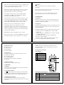
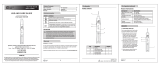
3.4 Description of Insulation
Tester Elements
1
V: - input terminal
2
COM - Common terminal
3
Display
4
Soft keys
5
Rotary function switch
6
Test button
3.5 Description of Press Buttons
)))
Enables / disables the buzzer
Δ
ZERO
Zero’s 40: and ranges to compensate for lead resistance
A-H
Selects auto hold function
Turns on/off backlight
TEST
Press to perform all tests except the voltage test
2
4
3
6
5
1
KΩ
ZERO
A - H
8.8.8.8
-8.8.8.8
0
1
0
0
2
0
0
3
0
0
4
0
0
5
0
0
6
0
0
7
0
0
8
0
0
9
0
0
x
1
0
0
0
0
0
.
5
1
2
3
4
5
6
7
1
0
1
5
2
0
3
0
5
0
1
0
0
mGΩ
KMΩ
V
V
z
AUTO HOLD

3.6 Description of LCD Symbols
Indicates voltage >30 V at terminals
Indicates buzzer is activated
AUTO HOLD
Display auto hold is activated
Indicates zero function is activated
:, k:, M:, V
Units of measurement being displayed
Indicates AC voltage measurement
Indicates DC voltage measurement
Indicates low battery
3.7 Battery Check
Set the rotary function switch to
and press the
TEST
button.
The battery voltage as a % and as a voltage will be displayed.
3.8 Auto Power Off
The unit will automatically power off after 5 minutes.
To disable/enable the auto power off function hold down
)))
for >2
seconds.
3.9 Display Auto Hold
To activate auto hold press
A-H
. The LCD will display AUTO HOLD
with HOLD blinking.
7
HOLD will stop blinking and the buzzer will sound when a stable
measurement occurs.
After the
TEST
button is released the measured value is displayed
and HOLD will resume blinking.
Press
A-H
to delete the value held on the display.
3.10 Display Backlight
Press
to turn on the backlight. Press again to turn the backlight
off.
3.11 Turning the Buzzer Off
Press
)))
to turn the buzzer off. The LCD no longer displays
Press again to turn the buzzer back on.
3.12 Zero Function
The zero function is used to compensate for test lead resistance
when using the 40: and
low resistance ranges.
Set the rotary function switch to the desired low resistance range.
Short the test leads or crocodile clips.
Press the
TEST
button to display the resistance of the leads.
Press
ZERO
to remove the lead resistance. The LCD will display the
symbol.
To remove the lead compensation press
ZERO
again. The LCD no
longer displays
.
8
9
3.13 Locking the Test Button
The
TEST
button may be locked into the test position by pressing it
down and turning it clockwise. Turn anticlockwise to unlock it.
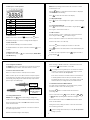
3.14 Use of the TL47 Test Leads
Before use, always check the continuity of the test leads.
When crocodile clips are to be fitted, or where it may be required
to plug the probes into 4mm sockets, the probe tip covers may be
removed by gently pulling them forward until they unclip from the
probe body to reveal 4mm plugs.
CAT III 1000V
CAT IV 600V
CAT II 1000V ONLY
DO NOT USE ON
CAT III or CAT IV
installations
3.15 Voltage Measurements
DO NOT press the
TEST
button when testing for voltage on a
circuit and ensure it is unlatched and released before proceeding.
Connect the black test lead to the COM terminal and the red test
lead to the V: terminal.
Taking all necessary safety precautions connect the test leads to
the circuit being measured.
Read the measured voltage from the display.
10
When a voltage > 30V DC or AC rms is detected the buzzer will
sound and the
symbol will flash on the LCD.
If a voltage test is being made prior to an insulation resistance,
continuity or resistance measurement and voltage is present
on the circuit under test, do not proceed.
In this event, remove the test leads from the circuit under test.
A suitably qualified electrician must proceed with caution to
investigate and remove the source of the voltage on the circuit
under test before proceeding with any other measurement.
3.16 Insulation Resistance Measurements
For safety and to avoid damage to the insulation tester, perform
insulation resistance tests in the following order.
Ensure the
TEST
button is unlatched and released before
proceeding.
Set the rotary switch to the
M:
position (IN2101) or
250V
,
500V
or
1000V
(IN2102) depending on the desired test voltage.
Connect the black test lead to the COM terminal and the red test
lead to the V: terminal.
Taking all necessary safety precautions connect the test leads to
the circuit being measured.
Perform a voltage measurement (see 3.15). Do not proceed if
voltage is present.

11
Press the
TEST
button. The buzzer will sound (unless disabled)
and the
symbol will be displayed on the LCD to indicate the
presence of the test voltage at the terminals.
Allow several seconds for the measurement to stabilise and read
the measured insulation resistance from the display.
The test voltage is displayed in the lower right corner of the LCD.
The test voltage decreases when measuring low values of
resistance. If it drops to <80V, a flashing indication of 0000 will be
displayed.
When the
TEST
button is released following the test, the circuit
under test will be discharged. If locked, unlock it before removing
the test leads.
Do not remove the test leads until the displayed voltage has
discharged to a safe level.
3.17 Continuity Measurements
Set the rotary switch to the
40:
position.
Connect the black test lead to the COM terminal and the red test
lead to the V: terminal.
If required, compensate for test lead resistance by performing the
zero function (see 3.12).
Taking all necessary safety precautions connect the test leads to
the circuit being measured.
12
Perform a voltage measurement (see 3.15). Do not proceed if
voltage is present.
Press the
TEST
button and read the measured continuity resistance
from the display.
3.18 k: Resistance Measurements
Set the rotary switch to the
K:
position.
Connect the black test lead to the COM terminal and the red test
lead to the V: terminal.
Taking all necessary safety precautions connect the test leads to
the circuit being measured.
Perform a voltage measurement (see 3.15). Do not proceed if
voltage is present.
Press the
TEST
button and read the measured resistance from the
display.
3.19 Resistance Measurements with Buzzer
Set the rotary switch to the
position.
Connect the black test lead to the COM terminal and the red test
lead to the V: terminal. If required, compensate for test lead
resistance by performing the zero function (see 3.12).
Taking all necessary safety precautions connect the test leads to
the circuit being measured.
Perform a voltage measurement (see 3.15). Do not proceed if
voltage is present.
Press the
TEST
button and read the measured continuity resistance
from the display.
If the resistance <30: the buzzer will sound.
4. MAINTENANCE
4.1 Battery Replacement
To avoid shock or injury, disconnect the insulation tester from
any external circuits and remove the test leads before proceeding.
The battery compartment is underneath the unit and can be
accessed by removing the two screws and lifting off the cover.
Fit 6 new 1.5V, AA alkaline batteries (IEC LR6, NEDA 15A) observing
correct polarity.
Replace the battery compartment cover and screws.
Note: Do not mix old and new batteries.
4.2 Fuse Replacement
To avoid shock, injury or damage to the multimeter, disconnect
it from any external circuits or components and remove the test
leads and battery before proceeding.
Replace only with the fuses specified.
13
The fuse is located in the battery compartment underneath the unit
and can be accessed by removing the two screws and lifting off the
cover.
Replace the fuse only with the original type F 0.5 A/600V
6.3 x 32mm fast blow ceramic fuse.
Replace the battery compartment cover and screws.
4.3 Test Lead Replacement
If the test leads become damaged they should be replaced.
The replacement test leads must have the same (or better)
overvoltage category rating as the TL47 test leads supplied.
4.4 Calibration
To maintain the integrity of measurements made using your
instrument, Martindale Electric recommends that it is returned
at least once a year to an approved Calibration Laboratory for
recalibration and certification.
Martindale Electric is pleased to offer you this service. Please
contact our Service Department for details.
Email: [email protected] Tel: 01923 650660
4.5 Cleaning
To reduce the risk of surface leakage, this instrument must be
kept in a clean condition.
Prior to cleaning, ensure that the instrument is disconnected
from any voltage source.
14

If contamination is found, clean with a damp soft cloth and if
necessary a mild detergent or alcohol. Do not use abrasives, abrasive
solvents, or detergents which can cause damage to the unit. If a mild
detergent is used, the unit should subsequently be thoroughly cleaned
with a water dampened soft cloth. After cleaning, dry and allow to
remain in a dry environment for 2 hours before use.
4.6 Repair & Service
There are no user serviceable parts in this unit other than those
that may be described in section 4. Return to Martindale Electric
if faulty. Our service department will quote promptly to repair any
fault that occurs outside the guarantee period.
Before the unit is returned, please ensure that you have checked
the unit, batteries, leads and for poor connections.
4.7 Storage Conditions
The instrument should be kept in warm dry conditions, away from
direct sources of heat or sunlight, with the batteries removed, and
in such a manner as to preserve the working life of the unit. It is
strongly advised that the unit is not kept in a tool box where other
tools may damage it.
5. WARRANTY AND LIMITATION OF LIABILITY
This Martindale product is warranted to be free from defects in
material and workmanship under normal use and service. The
warranty period is 2 years and begins on the date of receipt by the
end user. This warranty extends only to the original buyer or end-
user customer, and does not apply to fuses, disposable batteries,
test leads or to any product which, in Martindale’s opinion, has
been misused, altered, neglected, contaminated, or damaged by
15
accident or abnormal conditions of operation, handling or storage.
Martindale authorised resellers shall extend this warranty on new
and unused products to end-user customers only but have no
authority to extend a greater or different warranty on behalf of
Martindale.
Martindale’s warranty obligation is limited, at Martindale’s option, to
refund of the purchase price, free of charge repair, or replacement
of a defective product which is returned to Martindale within the
warranty period.
This warranty is the buyer’s sole and exclusive remedy and is in
lieu of all other warranties, expressed or implied, including but not
limited to any implied warranty of merchantability or fitness for a
particular purpose. Martindale shall not be liable for any special,
indirect, incidental or consequential damages or losses, including
loss of data, arising from any cause or theory.
Since some jurisdictions do not allow limitation of the term of
an implied warranty, or exclusion or limitation of incidental or
consequential damages, the limitations and exclusions of this
warranty may not apply to every buyer. If any part of any provision
of this warranty is held invalid or unenforceable by a court or other
decision-maker of competent jurisdiction, such holding will not
affect the validity or enforceability of any other provision or other
part of that provision.
Nothing in this statement reduces your statutory rights.
ELECTRICAL
All specified accuracies are at 23°C ± 5°C, <80% RH for 1 year.
Temperature coefficient:
Add 0.1 x (specified accuracy) per °C (0°C to 18°C, 28°C to 40°C)
All accuracies below are expressed as ± (percentage of reading + digits)
Voltage
Range Resolution Accuracy
600V 1V 3% + 5
Voltage warning: >30V
Specification
IN2101 & IN2102
Insulation Tester
Insulation Resistance
IN2101
Test
voltage
Test
current
Range
Operating
range to
BS EN 61557-2
(See note 1)
Resolution Accuracy
500V
1mA
at
0.5M:
4M:
0.1M:
to
1000M:
0.001M:
3% + 5
40M: 0.01M:
0
0.1M:
0
1M:
IN2102
Test
voltage
Test
current
Range
Operating
range to
BS EN 61557-2
(See note 1)
Resolution Accuracy
9
1mA
at
0.25 M:
0
0.1M:
to
1000M:
0
0 0
0 0
0 0
9
1mA
at
0.5M:
0
0.1M:
to
4000M:
0
0 0
0 0
0 0
9
1mA
at
1M:
0
0.1M:
to
5000M:
0
0 0
0 0
0 0
Specification
IN2101 & IN2102
Insulation Tester

Test voltage accuracy: 0% to +20%
Short circuit test current: <1.5mA
Auto discharge: Discharge time <1s for C=1μF or less
Maximum capacitive load: Operable with up to 1μF load
Live circuit detection: >30V DC or AC rms, test is inhibited
Overload protection: 600V DC or AC rms
Continuity Resistance
Range
Open circuit
test voltage
Short
circuit
test
current
Operating
range to
BS EN 61557-4
(See note 1)
Resolution Accuracy
40: 8V dc typical t 200mA
0.2: to 40: 0.01: 3% + 5
Overload protection: 600V DC or AC rms
k: Resistance
Range
Open circuit
test voltage
Short circuit
test current
Resolution Accuracy
1999k:
1.8V dc
typical
0.37mA
approx
d999.9: - 0.1:
t1000: - 1:
3% + 5
Overload protection: 600V DC or AC rms
)))
Resistance
Range
Open circuit
test voltage
Short circuit
test current
Resolution Accuracy
999.9: 2V dc approx.
0.37mA
approx.
0.1: 3% + 5
Overload protection: 600V DC or AC rms
Specification
IN2101 & IN2102
Insulation Tester
Note 1: The operating range where the operating uncertainty does not exceed
±30% in accordance with BS EN 61557-2 and BS EN 61557-4.
Operating uncertainty (B) = ± (|A| + 1,15 [ E
2
2
+ E
3
2
] )
where, A is the intrinsic uncertainty at reference conditions
E
2
is the variation due to supply voltage change
E
3
is the variation due to temperature change
GENERAL
Display: 5000 count liquid crystal display
Sample rate: 2.5 times/sec
Bar-graph: 51 segments
Overrange: (OL) is displayed
Power: 6 x 1.5V, AA alkaline batteries (IEC LR6, NEDA 15A)
Battery life (alkaline): >3000 measurements typical
Low battery indication:
symbol is displayed
Auto power off: After 5 minutes
Fuse: F 0.5 A/600 V 6.3x32mm fast blow ceramic
Dimensions: 90 x 210 x 54mm
Weight: Approx. 596g, including batteries
Includes: Carrying case, set of TL47 test leads, 6 x 1.5V AA batteries,
instructions
ENVIRONMENTAL
Temperature & Humidity
(Operating): 0°C to 40°C <70% R.H.
(Storage): -20°C to 60°C < 80% R.H., batteries removed
Altitude: up to 2000m
Pollution degree: 2
IP rating: IP44, not for use in wet conditions
Specification
IN2101 & IN2102
Insulation Tester
FUNCTIONALITY
Conforms to BS EN 61557-2 and BS EN 61557-4
SAFETY
Conforms to BS EN 61010-1, CAT III 600V
Class II, double insulation
EMC
Conforms to BS EN 61326-2-2
SPECIFICATION FOR TL47 TEST LEADS
Maximum voltage: 1000V AC/DC
Maximum current: 10A continuous
Connector: 4mm banana plug with fixed shroud
Environmental
Temperature (Operating & Storage): 0°C to 40°C
Altitude: up to 2000m
Pollution degree 2
Safety
Conforms to BS EN 61010-031, CAT IV 600V, CAT III 1000V, 10A (Probe tip
covers fitted)
CAT II 1000V, 10A (Probe tip covers removed)
Class II, double insulation
Specification
IN2101 & IN2102
Insulation Tester
17th Edition Testers
Accessories
Calibration Equipment
Continuity Testers
Electricians’ Kits
Environmental Products
Full Calibration & Repair Service
Fuse Finders
Digital Clamp Meters
Digital Multimeters
Labels
Microwave Leakage Detectors
Motor Maintenance Equipment
Multifunction Testers
Non-trip Loop Testers
Pat Testers & Accessories
Phase Rotation Testers
Proving Units
Safe Isolation kits
Socket Testers
Thermometers & Probes
Test Leads
Voltage Indicators
Specialist Metrohm Testers (4 & 5kV)
Specialist Drummond Testers
Check out what else you can get from Martindale:
Martindale Electric Company Limited
Metrohm House, Imperial Park, Imperial Way, Watford,
Hertfordshire, WD24 4PP, UK
Tel: +44(0)1923 441717 Fax: +44 (0)1923 446900
E-mail: [email protected]
Website: www.martindale-electric.co.uk
© 2016 Martindale Electric Company Ltd.
Registered in England No. 3387451. Rev 7 LIT IN2101
-
 1
1
-
 2
2
-
 3
3
-
 4
4
-
 5
5
-
 6
6


MARTINDALE IN2101 Insulation & Continuity Tester 500V User manual
- Category
- Cable network testers
- Type
- User manual
- This manual is also suitable for
Ask a question and I''ll find the answer in the document
Finding information in a document is now easier with AI
Related papers
-
MARTINDALE TEK404 Audible & Visual Continuity Tester User manual
-
-
-
-
-
-
-
-
-
 Martindale Electric PD440S 440V AC Proving Unit User manual

Other documents
-
Mastech MS5205B User manual
-
-
-
 Commercial Electric NCS-8904R Operating instructions
-
 Sperry instruments 3132MOV Owner's manual
-
Sperry VD6504 Operating instructions
-
Amprobe VPC-10 Voltage Continuity Tester User manual
-
 UEi IRT803 User manual
-
Metrohm E3511 User manual
-
UNI-T UT07B-EU User manual


