HUIZHOU EPEVER TECHNOLOGY CO., LTD. Tel:+86-10-82894896/82894112/+86-752-3889706 Website:www.epever.com
3 4
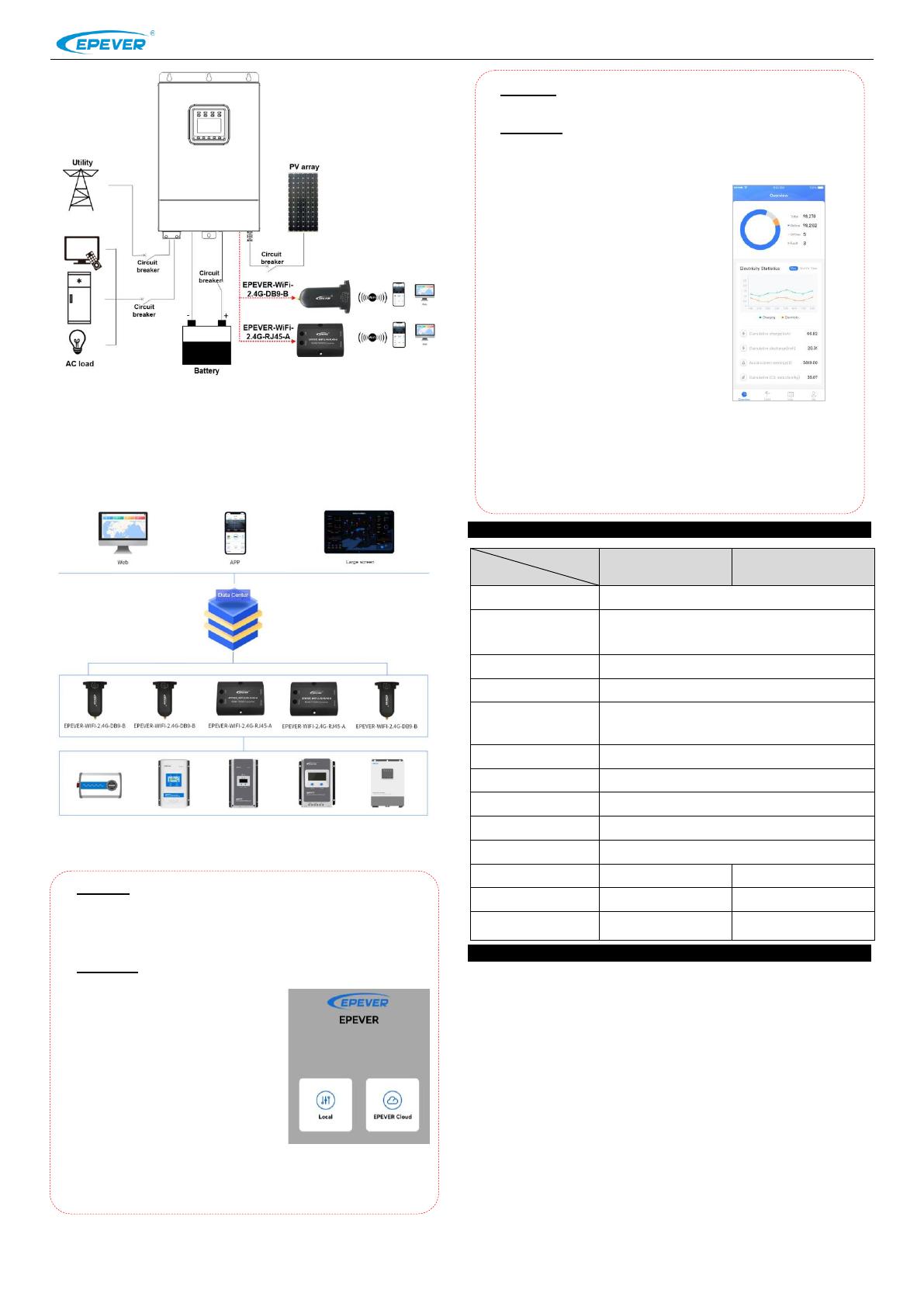
Note:EPEVER-WiFi-2.4G-RJ45-A is suitable for the controller, inverter, or
inverter/charger designed with an RJ45 port. EPEVER-WiFi-2.4G-DB9-B is suitable
for the device designed with a DB9 interface. For detailed connection cables,
refer to the connected device’s accessories list.
Step2: Users remotely monitor the controller, inverter, or inverter/charger
through a PC, large screen, or mobile phone APP.
The phone APP supports the AP(default) and STA working mode. According to
the login method and local network, it automatically enters the corresponding
working mode, no need to switch the working mode manually.
4. Specifications
Peak emission voltage: 5V@100mA
Idle voltage: 5V@40mA
EPEVER general communication standardV1-1.0
EPEVER IoT communication protocol V1.1
5. Disclaimers
The warranty does not apply to the following conditions:
Damage caused by improper use or inappropriate environment.
The parameter setting exceeds the WiFi terminal’s limit.
Damage caused by working temperature exceeds the rated range.
Unauthorized dismantling or attempted repair.
Damage caused by force majeure.
Damage occurred during transportation or handling.
Any changes without prior notice! Version number: V1.1
AP mode (default): When there is no local network, the WiFi
terminal cannot upload data to the cloud server. All performs
(including real-monitoring and parameter settings) are only carried
out between mobile phone and the WiFi terminal.
STA mode: When there is local network, the WiFi terminal uploads
data to the cloud server automatically.
Operations:
1) Turn on the WiFi switch on your
phone and open the cloud APP.
2) Click the "Local" icon to enter the
"WiFi" tab.
3) Click the corresponding name to
connect the WiFi terminal. Users
can obtain the name by checking
the QR code on the WiFi terminal.
4) Enter the real monitoring interface
after connecting the network
successfully (only downloaded
product models can be monitored).
Operations:
1) Connect the phone to local network.
2) Open the cloud APP, and click the
"EPEVER Cloud" icon to enter the
login interface.
3) Click the "Wifi On Cloud" icon to
enter the "Network Connection"
interface.
4) Connect the network by searching
the hotspots or scanning the QR
code on the WiFi terminal. After
successful network connection, the
WiFi terminal is added into the cloud
server automatically.
5) Click the “Confirm” button to return
the initial login interface.
6) Input the user name and password.
Click the "Sign In" button to enter the
cloud interface. All devices added
into the cloud server can be
monitored by the phone APP.

