Page is loading ...


PACKAGE CONTENTS
2
HARDWARE CONTENTS
21
22
23
24
25 28
27
26 29
30
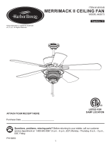
1. Canopy
2. Canopy Cover
3. Mounting Bracket
4. Downrod
5. Downrod Pin
6. Downrod Clip
7. Yoke Cover
8. Motor Assembly
9. Fitter Plate
10. Switch Housing
11. Light Kit
12. Glass Bowl
13. Finial Cap
14. Finial
15. Blade (x 5)
16. Blade Arm (x 5)
17. Bulb (x 2)
18. Pull Chain Extension (x2)
19. Hardware Kit
20. Owner’s Manual
21. Motor Screw (x 10)
22. Mounting Bracket
Screw(x 4)
23. Blade Screw (x 15)
24. Closemount Screw (x 3)
25. Set Screw (x 2)
26. Blade Washer (X 15)
27. Fitter Plate Screw (x 3)
28. Plug Button
29. Wire Connector (x 3)
30. Spring Washer (x 15)
Unpack your fan and check the contents. You should
have the following items:
PACKAGE CONTENTS
HARDWARE CONTENTS
Note: Some extra hardware has been included. The quantity
listed above is the number required for installation.
Hardware Kit
Owner’s
Manual
1
2
3
4
7
6
5
8
9
10
11
12
13
15
14
16
17
18
19
20

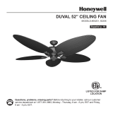
MOUNTING OPTIONS
3
Closemount
Downrod Mount
Angled Ceiling Mount (Up to 16 degrees)
17.98 in. B. 13.25 in. C. 11.91 in. D. 10.56 in. E. 5.08 in.
DIMENSION REFERENCE
E
DC
A
B
Choose one of the following mounting options:
Closemount method is best suited for ceilings lower than 8 feet. It does not utilize the downrod.
Downrod Mount is best suited for ceilings 8 ft. or higher. For taller ceilings you may want to use a longer
downrod (not included).
Angled Ceiling Mount is best suited for angled or vaulted ceilings. A longer downrod is sometimes necessary to
ensure proper blade clearance from the ceiling. If using the angle mount, check to ensure the ceiling angle is not
steeper than 16°.

WARNING
READ ALL SAFETY INFORMATION AND INSTALLATION INSTRUCTIONS BEFORE YOU BEGIN INSTALLING THE
FAN AND SAVE INSTRUCTIONS.
All set screws of the fan must be checked and retightened where necessary before installation.
To reduce the risk of personal injury, do not bend the blade brackets when installing the brackets, balancing
the blades or cleaning fan. Do not insert foreign objects in between rotating fan blades.
Before changing the fan direction, turn o the fan and wait for the fan blades to stop completely.
The safeguards provided by these safety instructions and by the separate installation instructions are not
meant to cover all possible conditions and situations that may occur. It must be understood that common
sense, caution and care are factors which can not be built into this product. These factors must be supplied
by the person(s) installing, caring for and operating the fan.
TO AVOID RISK OF ELECTRIC SHOCK, BE SURE TO SHUT OFF POWER AT THE MAIN FUSE OR CIRCUIT
BREAKER BOX BEFORE INSTALLING OR SERVICING THIS FIXTURE. TURNING OFF THE ELECTRICAL POWER
BY USING THE LIGHT SWITCH IS NOT SUFFICIENT TO PREVENT ELECTRICAL SHOCK.
TO REDUCE THE RISK OF INJURY, INSTALL THE FAN SO THAT THE BLADES ARE AT LEAST 7 FEET (2.1
METERS) ABOVE THE FLOOR AND AT LEAST 18 INCHES (0.5 METERS) FROM THE TIP OF THE BLADES TO
THE WALL.
TO REDUCE THE RISK OF FIRE, ELECTRIC SHOCK, OR PERSONAL INJURY, MOUNT TO OUTLET BOX
MARKED “ACCEPTABLE FOR FAN SUPPORT” AND USE MOUNTING SCREWS PROVIDED WITH THE OUTLET
BOX.
THE INSTALLATION HAS TO BE IN ACCORDANCE WITH THE NATIONAL ELECTRICAL CODE, ANSI/NFPA
70-1999 AND LOCAL CODES. IF YOU ARE UNFAMILIAR WITH THE METHODS OF INSTALLING ELECTRICAL
WIRING, SEEK THE SERVICES OF A QUALIFIED LICENSED ELECTRICIAN.
SAFETY INSTRUCTIONS
4
IMPORTANT:
Before you begin installing or using the fan, carefully read the entire manual. If unsure about any part of the
installation, contact a qualied electrician.
Save all instructions.
NOTE: The fan weight is Net Weight: 22.7 lb (10.29 kg). Be sure the outlet box (not included) is securely attached
to the building structure and is marked “Acceptable For Fan Support”. Failure to do so can result in serious injury.

5
ASSEMBLY INSTRUCTIONS
1
1. Turn OFF the electrical power at the main fuse or circuit
breaker.
Motor
Block
Motor
Motor ScrewFlat Washer
4
3
4. CLOSEMOUNT INSTALLATION (OPTIONAL)
a. Remove the canopy cover from the bottom of the
canopy.
b. Remove the three Phillips-head closemount screws from
the top of the motor assembly.
c. Align the holes in the bottom of the canopy with the
screw holes in the top of the motor housing. The larger
holes in the canopy will encompass 3 pre-installed screws.
Secure the canopy to the top of the motor assembly by
reinstalling the three Phillips-head closemount screws.
d. Hang the fan on the hook of the mounting bracket to
leave hands free during the wiring process.
Proceed to Step 9.
2
Mounting
Bracket Screw
3. Remove the motor screws, at washers and motor
blocks from the underside of the motor assembly. Discard
the motor blocks and at washers but keep the motor
screws for later.
If you wish to use the Downrod Mount (shown on page 3),
proceed to Step 5.
Closemount
Screw
Canopy
Hook
Mounting
Bracket
2. Loosen all four mounting brackets screws, then
completely remove the two mounting bracket screws
from the round holes of canopy. Set screws aside for later
use.
Warning: To reduce the risk of re electric shock,
or personal injury, mount to the outlet box marked
“acceptable for fan support” and use the mounting
screws and washers provided with the outlet box.

6
ASSEMBLY INSTRUCTIONS
7
Downrod
Clip
Set Screw
Yoke
Downrod
Pin
5
6
DOWNROD MOUNT
5. Remove the downrod clip and downrod pin from the
downrod. Then, loosen but do not remove the two set
screws in the yoke of the motor assembly.
6. Feed the wires coming from the yoke through the
yoke cover, canopy and downrod.
7. Insert the downrod into the yoke in the top of the
motor assembly and reinstall the downrod pin and
downrod clip. Then retighten the two set screws. With
wiring extending out of the top of the downrod,
measure 8 inches of lead wire and cut the excess wire
with wire cutters (not included). Then strip 1/2” of
insulation from the end of each wire.
Downrod
Canopy
Yoke Cover
Downrod Pin
Yoke
Downrod
Downrod Clip
Yoke
8
8. Lift the downrod into the mounting bracket. Rotate the
downrod until the tab in the mounting bracket is seated in
the slot in the downrod ball.
WARNING: The fan and/or downrod should not rotate in
the mounting bracket if installed correctly. Failure to align
the slot in the downrod ball with the tab may result in fan
falling causing serious injury or death.
Tab
Slot
Downrod
Mounting
Bracket

7
ASSEMBLY INSTRUCTIONS
Black (Hot)
Wire Connector
White (Neutral)
Bare/Green (Ground)
Black
Blue
White
Green
11
10 10. Raise the canopy, ensuring the two mounting bracket
screws are aligned with the J-shaped slots in the canopy.
Then turn the canopy clockwise until the mounting
bracket screws are completely engaged in the J-shaped
slots. Install the two previously removed mounting
bracket screws in the round holes. Securely tighten all four
mounting bracket screws.
11. Attach the blades to blade arms using the blade
screws, spring washers, and blade washers from the
hardware kit.
9. Use wire connectors to connect the fan wires to the
power supply wires according to the wiring diagram and
the following instructions:
• Connect the white wire from the fan to the white (neutral/
common) supply wire.
• Connect the black and blue wires from the fan to the
black (hot/power) supply wire.
• Connect the green wire from the fan to the bare/green
(ground) supply wire.
Note: If a second hot/power wire is available from the
outlet box, connect it to the blue (light power) fan wire for
separate fan and light switches.
Important: After the connections have been made, the
wires should be turned upward and pushed carefully
up into the outlet box. Place the black and white wire
connections on opposite sides of the outlet box.
9
Canopy
J-shaped Slot
Round
Hole
Blade
Arm
Blade Screw
Spring Washer
Blade Washer
Blade
Mounting
Bracket Screw
Blade Arm
Motor Screw
Motor Assembly
12
12. Secure the blade arm to the underneath side of the
motor using motor screws removed in Step 3. Completely
secure each blade arm to motor before moving to the
next.
To install the fan without the light kit, skip to step 17.

8
ASSEMBLY INSTRUCTIONS
14
13. Remove the three tter plate screws from the tter
plate. Connect the 9-pin connectors from the fan to the
9-pin connectors from the light kit. Then, use the tter
plate screws to secure the light kit to the tter plate.
14. Install the E26-base LED bulbs into the sockets of the
light kit. Then, remove the nial, nial cap, hex nut and
rubber washer from the threaded rod at the bottom of the
light kit.
Replacement bulbs: Use E26-base LED, CFL, or
incandescent (60 watt max.) bulbs.
13
Switch
Housing
Screw
Light Kit
9-pin
Connector
Bulb Socket
15
15. Feed the pull chain through the center hole in the
glass bowl and rubber washer. Then, lift the the glass bowl
and rubber washer over the threaded rod and secure the
glass using the hex nut. Feed the pull chain through the
nial cap nial. Lift the nial cap up to the glass and secure
it with the nial.
Finial
Finial
Finial Cap
Glass Bowl
Chain
Guide
Finial Cap
Hex Nut
Hex Nut
Rubber Washer
Rubber Washer
16
16. Insert the pull chain coming from the switch housing
down through the chain guide.
Skip to Step 19.

9
Pull Chain Extension
ASSEMBLY INSTRUCTIONS
20. Restore the power at the main fuse or circuit breaker.
18. NO LIGHT KIT INSTALLATION (CONT’D)
a. Remove the three switch housing screws from the tter
plate. Then, install the switch housing to the tter plate
with the three switch housing screws.
Switch
Housing
Fitter Plate
Switch
Housing
Screw
18
19
20
19. Attach pull chain extension(s) to the pull chain(s).
Switch
Housing
Plug Button
Switch
Housing
Light Kit
Lock Washer Hex Nut
17. NO LIGHT KIT INSTALLATION (OPTIONAL)
To install the fan without the light kit, remove the
preassembled hex nut and lock washer from the threaded
rod inside the switch housing. Disconnect the single-pin
connectors inside the switch housing. Then, remove the
light kit from the switch housing.
Insert the plug button into the center hole of the switch
housing.
17

10
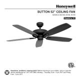
OPERATING INSTRUCTIONS
1
2. Using a ceiling fan will allow you to raise your
thermostat setting in summer and lower your thermostat
setting in winter without feeling a dierence in your
comfort.
Note: Wait for the fan to stop before moving the reverse
switch.
In warmer weather, push the reverse switch left which
will result in downward airow creating a wind chill eect.
In cooler weather, push the reverse switch right, which
will result in upward airow that can help move stagnant,
hot air o the ceiling area.
IMPORTANT: The reverse switch must be set either
completely left or right in order for the fan to function
correctly. If the reverse switch is set in the middle
position, the fan will not operate.
1. The fan pull chain extends from the switch housing. It
has four positions to control fan speed. One pull is HIGH,
two is MEDIUM, three is LOW and four turns the fan OFF.
The light pull chain is located in the center of the nial. It
turns the light ON and OFF.
2
Fan Pull
Chain
Reverse Switch
Light Pull
Chain

11
If you have diculty operating your new ceiling fan, it may be the result of incorrect assembly, installation or
wiring. In some cases, these installation errors may be mistaken for defects. If you experience any faults, please
check the Troubleshooting section below. If a problem cannot be remedied or you are experiencing diculty in
installation, please contact the Service Department: 1-706-3267, 9 a.m.- 5 p.m. Central time.
PROBLEM SUGGESTED REMEDY
1. Fan does not start 1. Check main and branch circuit fuses or circuit breakers.
2. Check power supply wire connections to fan and switch wire connections in
switch housing.
CAUTION: Make sure main power is turned o.
3. Make sure forward/reverse switch pushed completely left or right. Fan will not
operate when switch is in the middle.
4. Make sure that the wall control is turned ON.
1. Make sure all screws in motor housing are snug, but not overtightened.
2. Make sure the screws which attach the blade arm to the motor are tight.
3. Make sure wire connectors in switch housing are not rattling against each other
or against the interior wall of the switch housing.
CAUTION: Make sure main power is turned o before entering switch housing.
4. Some fan motors are sensitive to signals from Solid State variable speed controls.
DO NOT USE a Solid State variable speed control.
1. Ensure all blades are screwed rmly into blade arms.
2. Ensure all blade arms are tightened securely to motor.
3. Ensure canopy and mounting bracket are tightened securely to outlet box and
outlet box is mounted rmly to ceiling joist.
4. Switch one blade with a blade from the opposite side. Or balance the fan using a
balancing kit.
5. If blade wobble is still noticeable, interchanging two adjacent (side by side)
blades can redistribute the weight and possibly result in smoother operation.
1. Check blue wire from fan to make sure it is connected to hot (black) power
supply wire or to a separate power supply wire from outlet box.
2. Check for loose or disconnected wires in fan switch housing.
3. Check for loose or disconnected wires in light kit.
4. Check for faulty light bulbs.
CAUTION: Make sure main power is turned o before entering switch housing.
1. Make sure the reverse switch is in the left position.
2. Change to higher fan speed by pulling the fan pull chain
2. Fan is noisy
3. Fan wobbles
4. Light does not work:
5. Weak airow:
TROUBLESHOOTING

LIMITED LIFETIME WARRANTY
To obtain Service, please contact the Service Department:
1-877-706-3267, 9 a.m.- 5 p.m. central time.
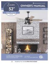
Model Name: 52” Ceiling Fan
Model No: 80018 - White
12
Subject to the limitations set forth below, Hong Kong China Electric appliance Company (HKC) warrants
the fan motor for this ceiling fan to be free from defects in workmanship and material for the life of
the product. Also, subject to the limitations below, HKC warrants all ceiling fan parts (“ceiling fan parts”
excludes the motor and parts made in whole or in part with glass) to be free from defects in workmanship
and material for a period of one year after the date of purchase by the original purchaser at retail.
All claims must be made by the original purchaser, whether such purchaser purchased the product through a
store or contractor. Ceiling fan part defects must be reported within the rst year from the date of purchase.
Parts made in whole or in part with glass and the nishes of metal and other surfaces are not warranted.
Purchasers are responsible for all costs of removing and reinstalling the product. Any damage to any
part caused by ordinary wear and tear, accident, misuse, or improper installation, is not covered by this
warranty. HKC assumes no responsibility whatsoever for fan installation. Any service performed by a non-
licensed electrician will render the warranty invalid.
HKC’s sole responsibility shall be to repair or replace the motor, parts, or product within the terms stated
above. HKC shall not be liable for any loss or damage of any kind, including any incidental or consequential
damages resulting directly or indirectly, from any breach of warranty, express or implied, or any other
failure of this product. Some states do not allow the exclusion or limitation of incidental or consequential
damages so this limitation may not apply to you.
If the original purchaser ceases to own the fan, this warranty is voided.
Should the purchaser encounter a problem with your fan related to defects in workmanship or materials
within the warranty period associated with the defective part, HKC agrees to replace the defective part
without charge, or at its option, to replace the ceiling fan with a comparable or superior model.
HKC’s warranties are limited to the written warranties set out in this HKC ceiling fan limited lifetime
warranty. All other express and implied warranties, including, without limitation, the implied warranty of
tness for a particular purpose and the implied warranty of merchantability are disclaimed. Some states do
not allow the disclaimer of implied warranties, so this disclaimer may not apply to you.
To obtain warranty service, please write down your model number and call Customer Service at
1-877-706-3267. Please have a copy of the receipt as proof of purchase.
/