Blueridge BMKH0938O Owner's manual
- Category
- Split-system air conditioners
- Type
- Owner's manual
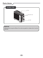
The Blueridge BMKH0938O is a split air conditioner with energy-saving features and a user-friendly design. It provides both cooling and heating functions to offer year-round temperature control. The air conditioner has a compact indoor unit and a durable outdoor unit that can withstand various weather conditions. Installation should be performed by qualified professionals.
The Blueridge BMKH0938O is a split air conditioner with energy-saving features and a user-friendly design. It provides both cooling and heating functions to offer year-round temperature control. The air conditioner has a compact indoor unit and a durable outdoor unit that can withstand various weather conditions. Installation should be performed by qualified professionals.


-
 1
1
-
 2
2
-
 3
3
-
 4
4
-
 5
5
-
 6
6
-
 7
7
-
 8
8
-
 9
9
-
 10
10
-
 11
11
-
 12
12
-
 13
13
-
 14
14
-
 15
15
-
 16
16
-
 17
17
-
 18
18
-
 19
19
-
 20
20
-
 21
21
-
 22
22
-
 23
23
-
 24
24


Blueridge BMKH0938O Owner's manual
- Category
- Split-system air conditioners
- Type
- Owner's manual
The Blueridge BMKH0938O is a split air conditioner with energy-saving features and a user-friendly design. It provides both cooling and heating functions to offer year-round temperature control. The air conditioner has a compact indoor unit and a durable outdoor unit that can withstand various weather conditions. Installation should be performed by qualified professionals.
Ask a question and I''ll find the answer in the document
Finding information in a document is now easier with AI
Other documents
-
GREE LIVV09HP115V1AO User manual
-
Dettson LPD Installation guide
-
Tosot TW09HQ2C2A Outdoor Unit Owner's Manual
-
Gibson 16 SEER Single Zone, LS(A,K)4DL Installation guide
-
Cooper&Hunter GWH09QC-D3DNA1D Victoria Installation Manual
-
Sinclair ASP-18AI User manual
-
-
HTW WAC-R32 Owner's manual
-
-
GREE Hansol Out Dreds Owner's manual