
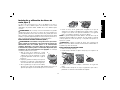
D28474, D28476, D28494, D28496
Esmeriladora Angular
Large Angle Grinders
D284076, D28493
Lijadora/Esmeriladora Angular
Large Angle Sander/Grinder
INSTRUCTIVO DE OPERACIÓN, CENTROS DE SERVICIO Y PÓLIZA DE
GARANTÍA. ADVERTENCIA: LÉASE ESTE INSTRUCTIVO ANTES DE USAR EL
PRODUCTO.
MANUAL DE INSTRUCCIONES
INSTRUCTION MANUAL
¿Dudas? Visítenos en Internet: www.dewalt.com
Questions? See us on the World Wide Web at www.dewalt.com
Page is loading ...
Page is loading ...
Page is loading ...
Page is loading ...
Page is loading ...
Page is loading ...
Page is loading ...
Page is loading ...
Page is loading ...
Page is loading ...
Page is loading ...
Page is loading ...
Page is loading ...
Page is loading ...
Page is loading ...
Page is loading ...
Page is loading ...
Page is loading ...
Page is loading ...
Page is loading ...
Page is loading ...

21
English
Defi nitions: Safety Guidelines
The definitions below describe the level of severity for each
signal word. Please read the manual and pay attention to these
symbols.
DANGER: Indicates an imminently hazardous situation which,
if not avoided, will result in death or serious injury.
WARNING: Indicates a potentially hazardous situation which,
if not avoided, could result in death or serious injury.
CAUTION: Indicates a potentially hazardous situation which, if
not avoided, may result in minor or moderate injury.
NOTICE: indicates a practice not related to personal injury
which, if not avoided, may result in property damage.
WARNING: To reduce the risk of injury, read the instruction
manual.
General Power Tool Safety Warnings
WARNING! Read all safety warnings and all instructions
Failure to follow the warnings and instructions may result in
electric shock, fire and/or serious injury.
SAVE ALL WARNINGS AND INSTRUCTIONS
FOR FUTURE REFERENCE
The term “power tool”in the warnings refers to your mains-operated
(corded) power tool or battery-operated (cordless) power tool.
1) WORK AREA SAFETY
a) Keep work area clean and well lit. Cluttered or dark areas
invite accidents.
b) Do not operate power tools in explosive atmospheres,
such as in the presence of flammable liquids, gases or
dust. Power tools create sparks which may ignite the dust or
fumes.
c) Keep children and bystanders away while operating a
power tool. Distractions can cause you to lose control.
2) ELECTRICAL SAFETY
a) Power tool plugs must match the outlet. Never modify
the plug in any way. Do not use any adapter plugs with
earthed (grounded) power tools. Unmodified plugs and
matching outlets will reduce risk of electric shock.
b) Avoid body contact with earthed or grounded surfaces
such as pipes, radiators, ranges and refrigerators. There
is an increased risk of electric shock if your body is earthed or
grounded.
c) Do not expose power tools to rain or wet conditions.
Water entering a power tool will increase the risk of electric
shock.
d) Do not abuse the cord. Never use the cord for carrying,
pulling or unplugging the power tool. Keep cord away
from heat, oil, sharp edges or moving parts. Damaged or
entangled cords increase the risk of electric shock.
e) When operating a power tool outdoors, use an extension
cord suitable for outdoor use. Use of a cord suitable for
outdoor use reduces the risk of electric shock.
f) If operating a power tool in a damp location is unavoidable,
use a residual current device (RCD) protected supply.
Use of an RCD reduces the risk of electric shock.
3) PERSONAL SAFETY
a) Stay alert, watch what you are doing and use common
sense when operating a power tool. Do not use a power
tool while you are tired or under the influence of drugs,
alcohol or medication. A moment of inattention while
operating power tools may result in serious personal injury.
b) Use personal protective equipment. Always wear eye
protection. Protective equipment such as dust mask, non-

22
English
skid safety shoes, hard hat, or hearing protection used for
appropriate conditions will reduce personal injuries.
c) Prevent unintentional starting. Ensure the switch is in
the off position before connecting to power source and/
or battery pack, picking up or carrying the tool. Carrying
power tools with your finger on the switch or energising power
tools that have the switch on invites accidents.
d) Remove any adjusting key or wrench before turning the
power tool on. A wrench or a key left attached to a rotating
part of the power tool may result in personal injury.
e) Do not overreach. Keep proper footing and balance at
all times. This enables better control of the power tool in
unexpected situations.
f) Dress properly. Do not wear loose clothing or jewellery.
Keep your hair, clothing and gloves away from moving
parts. Loose clothes, jewellery or long hair can be caught in
moving parts.
g) If devices are provided for the connection of dust
extraction and collection facilities, ensure these are
connected and properly used. Use of dust collection can
reduce dust-related hazards.
4) POWER TOOL USE AND CARE
a) Do not force the power tool. Use the correct power tool
for your application. The correct power tool will do the job
better and safer at the rate for which it was designed.
b) Do not use the power tool if the switch does not turn it
on and off. Any power tool that cannot be controlled with the
switch is dangerous and must be repaired.
c) Disconnect the plug from the power source and/or the
battery pack from the power tool before making any
adjustments, changing accessories, or storing power
tools. Such preventive safety measures reduce the risk of
starting the power tool accidentally.
d) Store idle power tools out of the reach of children and
do not allow persons unfamiliar with the power tool or
these instructions to operate the power tool. Power tools
are dangerous in the hands of untrained users.
e) Maintain power tools. Check for misalignment or binding
of moving parts, breakage of parts and any other
condition that may affect the power tool’s operation. If
damaged, have the power tool repaired before use. Many
accidents are caused by poorly maintained power tools.
f) Keep cutting tools sharp and clean. Properly maintained
cutting tools with sharp cutting edges are less likely to bind and
are easier to control.
g) Use the power tool, accessories and tool bits etc., in
accordance with these instructions taking into account
the working conditions and the work to be performed.
Use of the power tool for operations different from those
intended could result in a hazardous situation.
5) SERVICE
a) Have your power tool serviced by a qualified repair
person using only identical replacement parts. This will
ensure that the safety of the power tool is maintained.
ADDITIONAL SPECIFIC SAFETY RULES
Additional safety rules for grinders
• Your grinder has been designed for grinding and cutting
masonry and steel.
WARNING: Do not cut or grind light metal with a magnesium
content exceeding 80% since this type of metal is flammable.
• Do not use any accessories other than fibre reinforced
grinding and cutting discs.
• Use the grinding and cutting discs recommended by the
manufacturer only.

23
English
• The max. allowable speed of the grinding wheel or cutting
disc must always be equal to or greater than the no-load
speed of the tool specified on the nameplate.
• Do not cut workpieces requiring a maximum depth of cut
exceeding that of the cutting disc.
• Do not use grinding and cutting discs that do not conform
to the dimensions stated in the technical data. Do not use
any spacers to make a disc fit onto the spindle.
• Inspect grinding and cutting discs before each use. Do not
use chipped, cracked or otherwise defective discs.
• If provided, ensure that blotters are used when the disc is
fitted onto the spindle.
• When applying a threaded hole disc, ensure that the thread
is long enough to accept the spindle.
• Ensure that the grinding or cutting disc is mounted
correctly before use.
• Let the tool run at no-load in a safe position for at least 30
seconds. If there is a considerable vibration or if any other defect
occurs, stop the tool and check it to determine the cause.
• Do not operate this tool without the guard in place.
• Check that the workpiece is properly supported.
• Do not operate the tool near flammable liquids, gases or
dust. Sparks or hot chips from cutting or arcing motor brushes
may ignite combustible materials.
• Do not operate the tool while standing in line with the disc.
Keep other persons away from the work area.
• Do not use cutting discs for side grinding.
• Do not operate the spindle lock while the tool is running.
• Beware that after switching off the tool the wheel continues
to rotate for a short period.
• Always store grinding and cutting discs in a dry place.
Causes and Operator Prevention of
Kickback
• Kickback is a sudden reaction to a pinched or snagged rotating
wheel, backing pad, brush or any other accessory. Pinching or
snagging causes rapid stalling of the rotating accessory which
in turn causes the uncontrolled power tool to be forced in the
direction opposite of the accessory’s rotation at the point of the
binding.
• For example, if an abrasive wheel is snagged or pinched by the
workpiece, the edge of the wheel that is entering into the pinch
point can dig into the surface of the material causing the wheel
to climb out or kick out. The wheel may either jump toward or
away from the operator, depending on direction of the wheel’s
movement at the point of pinching. Abrasive wheels may also
break under these conditions.
• Kickback is the result of tool misuse and/or incorrect operating
procedures or conditions and can be avoided by taking proper
precautions as given below:
a) Maintain a firm grip on the power tool and position your
body and arm to allow you to resist kickback forces.
Always use auxiliary handle, if provided, for maximum
control over kickback or torque reaction during start up.
The operator can control torque reaction or kickback forces, if
proper precautions are taken.
b) Never place your hand near the rotating accessory.
Accessory may kickback over your hand.
c) Do not position your body in the area where power tool
will move if kickback occurs. Kickback will propel the tool
in direction opposite to the wheel’s movement at the point of
snagging.
d) Use special care when working corners, sharp edges etc.
Avoid bouncing and snagging the accessory. Corners,
sharp edges or bouncing have a tendency to snag the rotating
accessory and cause loss of control or kickback.

24
English
e) Do not attach a saw chain woodcarving blade or toothed
saw blade. Such blades create frequent kickback and loss of
control.
Safety Warnings Specifi c for
Grinding Operations
a) Use only wheel types that are recommended for your
power tool and the specific guard designed for the
selected wheel. Wheels for which the power tool was not
designed cannot be adequately guarded and are unsafe.
b) The guard must be securely attached to the power tool
and positioned for maximum safety, so the least amount
of wheel is exposed towards the operator. The guard
helps to protect operator from broken wheel fragments and
accidental contact with wheel.
c) Wheels must be used only for recommended applications.
For example: do not grind with the side of cut-off wheel.
Abrasive cut-off wheels are intended for peripheral grinding,
side forces applied to these wheels may cause them to shatter.
d) Always use undamaged wheel flanges that are of correct
size and shape for your selected wheel. Proper wheel
flanges support the wheel thus reducing the possibility of wheel
breakage. Flanges for cut-off wheels may be different from
grinding wheel flanges.
e) Do not use worn down wheels from larger power tools.
Wheel intended for larger power tool is not suitable for the
higher speed of a smaller tool and may burst.
Safety Warnings Specifi c
for Wire Brushing Operations
a) Be aware that wire bristles are thrown by the brush even
during ordinary operation. Do not overstress the wires
by applying excessive load to the brush. The wire bristles
can easily penetrate light clothing and/or skin.
b) If the use of a guard is recommended for wire brushing,
do not allow any interference of the wire wheel or brush
with the guard. Wire wheel or brush may expand in diameter
due to work and centrifugal forces.
Additional Safety Warnings for Grinders
• Air vents often cover moving parts and should be avoided.
Loose clothes, jewelry or long hair can be caught in moving parts.
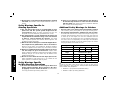
• An extension cord must have adequate wire size for safety.
An undersized cord will cause a drop in line voltage resulting in loss
of power and overheating. When using more than one extension
to make up the total length, be sure each individual extension
contains at least the minimum wire size. The following table shows
the correct size to use depending on cord length and nameplate
ampere rating. If in doubt, use the next heavier gauge. The smaller
the gauge number, the heavier the cord.
Voltage (Volts)
Total length of cord in meters (m)
120–127V 0–7 7–15 15–30 30–50
220–240V 0–15 15–30 30–60 60–100
Rated Ampere
range
Minimal cross-sectional area of the
cord in meters (mm
2
)
0–6A 1.0 1.5 1.5 2.5
6–10A 1.0 1.5 2.5 4.0
10–12A 1.5 1.5 2.5 4.0
12–16A 2.5 4.0 Not Recommended
WARNING: ALWAYS USE SAFETY GLASSES. Everyday
eyeglasses are NOT safety glasses. Also use face or dust mask if
cutting operation is dusty. All users and bystanders MUST ALWAYS
wear certified safety equipment:
• ANSI Z87.1 eye protection (CAN/CSA Z94.3),
• ANSI S12.6 (S3.19) hearing protection,

25
English
CAUTION: To reduce the risk of personal injury, use extra care
when working into a corner or edge because a sudden, sharp
movement of the tool may be experienced when the wheel or other
accessory contacts a secondary surface or a surface edge.
• The label on your tool may include the following symbols. The
symbols and their definitions are as follows:
V .......... volts A .......... amperes
Hz ........ hertz W......... watts
min ......minutes
....... alternating current
...direct current ....... alternating or direct current
........ Class I Construction
n
o ........ no load speed
............
............(grounded) ........ earthing terminal
........Class II Construction ......... safety alert symbol
............(double insulated) BPM .... beats per minute
…/min . per minute RPM .... revolutions per minute
IPM ......impacts per minute sfpm .... surface feet per minute
SAVE THESE INSTRUCTIONS
FOR FUTURE USE
Motor
Be sure your power supply agrees with the nameplate marking.
Voltage decrease of more than 10% will cause loss of power and
overheating. All D
EWALT tools are factory tested; if this tool does not
operate, check the power supply.
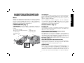
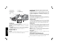
DESCRIPTION (FIG. 1)
WARNING: Never modify the power tool or any part of it. Damage
or personal injury could result.
• NIOSH/OSHA/MSHA respiratory protection.
WARNING: Some dust created by power sanding, sawing,
grinding, drilling, and other construction activities contains chemicals
known to cause cancer, birth defects or other reproductive harm.
Some examples of these chemicals are:
• lead from lead-based paints,
• crystalline silica from bricks and cement and other masonry
products, and
• arsenic and chromium from chemically-treated lumber.
Your risk from these exposures varies, depending on how often you
do this type of work. To reduce your exposure to these chemicals:
work in a well ventilated area, and work with approved safety
equipment, such as those dust masks that are specially designed to
filter out microscopic particles.
• Avoid prolonged contact with dust from power sanding,
sawing, grinding, drilling, and other construction activities.
Wear protective clothing and wash exposed areas with
soap and water. Allowing dust to get into your mouth, eyes, or
lay on the skin may promote absorption of harmful chemicals.
WARNING: Use of this tool can generate and/or disburse dust,
which may cause serious and permanent respiratory or other injury.
Always use NIOSH/OSHA approved respiratory protection appropriate
for the dust exposure. Direct particles away from face and body.
WARNING: Always wear proper personal hearing protection
that conforms to ANSI S12.6 (S3.19) during use. Under some
conditions and duration of use, noise from this product may
contribute to hearing loss.
WARNING: Always use eye protection. All users and
bystanders must wear eye protection that conforms to ANSI Z87.1.
WARNING: When not in use, place grinder on a stable
surface where it will not move inadvertantly, roll or cause a
tripping or falling hazard. Serious personal injury may result.

26
English
A. Trigger Switch E. Spindle
B. Lock On Button F. Soft Mount
C. Spindle Lock G. Rubber Bumper
D. Side Handle
A
B
D
E
F
C
G
FIG. 1
INTENDED USE
Large angle grinders and large angle sanders are designed for heavy
material removal in extended use applications.
DO NOT use under wet conditions or in presence of flammable
liquids or gases.
This heavy-duty angle grinder and sanders are professional power
tool. DO NOT let children come into contact with the tool. Supervision
is required when inexperienced operators use this tool.
Features (Fig. 1)
SWITCH
The tool is controlled by a trigger switch (A). A lock-on button (B)
provides increased comfort in extended use applications.
ROTATING GEAR CASE (D28474, D28476, D284076, D28493,
D28494, D28496)
For applications in which a tool will be dedicated for uses in edge
grinding and finishing work, the gear case may be rotated 90° left
or right of its original position. See Rotating the Gear Case under
Assembly and Adjustment for instructions on rotating the gear
case.
MULTIPLE SIDE HANDLE POSITIONS
The side handle can be properly positioned in five lo ca tions based on
personal preference and application. The side handle must be used
at all times to maintain proper control of the tool.
RUBBER BUMPER
The gear case rubber bumper (G) may wear with use. The bumper
can be replaced and is available at extra cost from D
EWALT service
centers and D
EWALT dealers. Replacement should be performed by
D
EWALT authorized service centers or qualified service personnel.
SPINDLE LOCK
The spindle lock pin is provided to prevent the spindle from rotating
when installing or removing wheels. Operate the spindle lock pin only
when the tool is turned off and unplugged from the power source. To
engage the lock, depress the spindle lock button (C) and rotate the
spindle until you are unable to rotate it further.
NOTE: Never depress the spindle lock button while the grinder is
running. Never turn on the grinder while the spindle lock button is
depressed. Damage to your tool may result.
SOFT MOUNT
The grinder is equipped with a soft mount, enabling easy wheel
installation and removal.
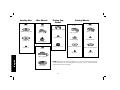
Accessories and Attachments
It is important to choose the correct guards, backing pads and
flanges to use with grinder accessories. See the chart on pages
27–29 for information on choosing the correct accessories.

27
English
ASSEMBLY AND ADJUSTMENTS
WARNING: To reduce the risk of serious personal injury,
turn tool off and disconnect tool from power source before
making any adjustments or removing/installing attachments
or accessories. Before reconnecting the tool, depress and
release the trigger switch to ensure that the tool is off. An
accidental start-up can cause injury.
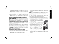
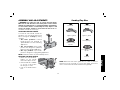
ATTACHING THE SIDE HANDLE
To install the side handle, thread the
handle into one of the five positions listed
below and tighten securely by turning
clockwise.
• Two front positions: Forward
handle positions are designed for
optimized balance in surface finishing
applications.
• Two rear positions: Rear handle
positions are designed for optimized
balance in edge grinding applications.
• One top position: Top handle
position is designed for edge grinding applications.
NOTE: D284076 includes only three handle positions.
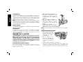
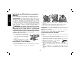
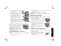
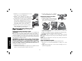
ROTATING THE REAR HANDLE
1. Unlock the rear handle by
M
pulling out the handle
re lease lever (M) as shown.
2. Rotate handle into available
0°, 30°, 60° or 90° position
left OR right of center.
3. Push in the handle release
lever.
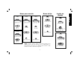
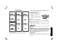
Sanding Flap Disc
NOTE: Wheel size must match guard size; i.e., a new 7" (180 mm
wheel may not be used with a 9" (230 mm) guard. The bottom
surface of wheel must be inside the bend of the guard lip.
hubbed sanding
flap disc
backing flange
non-hubbed sanding
flap disc
clamp nut
Type 27 guard
Type 27 guard
soft mount soft mount

28
English
Sanding Disc
mount
rubber backing pad
sanding disc
clamp nut
Flaring Cup
Stones
Type 11 flaring cup guard
backing flange
flaring cup stone
Cutting Wheels
mount
type 1 guard
backing flange
diamond cutting wheel
mount
type 1 guard
backing flange
abrasive cutting wheel
clamp nut clamp nut
NOTE: Wheel size must match guard size; i.e., a new 7" (180 mm) wheel may
not be used with a 9" (230 mm) guard. The bottom surface of wheel must be
inside the bend of the guard lip.
Wire Wheels
mount
wire wheel
type 27 guard
mount
wire cup brush
type 27 guard

29
English
4. Before turning the tool on, ensure that the handle is locked into a
position and the handle release lever has returned to the original
position flush with the tool housing.
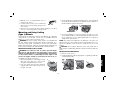
ROTATING THE GEAR CASE
1. Remove the four corner screws
90˚
90˚
attaching the gear case to motor
housing.
2. Without separating the gear
case from motor housing, rotate
the gear case head to desired
position.
NOTE: If the gear case and motor
housing become separated by more
than 1/8" (3mm), the tool must be serviced and re-assembled by a
D
EWALT service center. Failure to have the tool serviced may cause
brush, motor and bearing failure.
3. Re-install screws to attach the gear case to the motor housing.
Tighten screws to 20 in lbs torque. Over tightening could cause
screws to strip.
OPERATION
WARNING: Always observe the safety instructions and applicable
regulations.
WARNING: To reduce the risk of serious personal injury,
turn tool off and disconnect tool from power source before
making any adjustments or removing/installing attachments
or accessories. Before reconnecting the tool, depress and
release the trigger switch to ensure that the tool is off. An
accidental start-up can cause injury.
POWER SOURCE
Plug the large angle grinder into a dedicated electrical circuit.
Operating this tool on a circuit with other tools will decrease tool
performance.
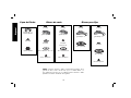
Grinding Wheels
mount
type 27 guard
type 27 hubbed
wheel
mount
type 28 guard
type 28 hubbed
wheel
mount
type 27 guard
backing flange
type 27 non-hubbed
wheel
clamp nut
mount
type 27 guard
backing flange
type 28 non-hubbed
wheel
clamp nut
NOTE: Wheel size must match guard size; i.e., a new 7" (180 mm)
wheel may not be used with a 9" (230 mm) guard. The bottom
surface of wheel must be inside the bend of the guard lip.

30
English
SWITCH
CAUTION: Before connecting the tool to a
A
B
power source or after a power failure, depress
and release the trigger switch (A) once without
depressing the lock-on button (B) to ensure
that the switch is in the off position. If the
trigger switch is locked on, the tool will start
unexpectedly when power is reconnected to
the tool. Hold the side handle and rear handle
firmly to maintain control of tool at start up and during use.
TRIGGER OPERATION
To turn the tool on, depress the trigger switch (A). The tool will remain
running while the trigger is depressed. Turn the tool off by releasing
the trigger.
TRIGGER OPERATION WITH LOCK-ON FEATURE
To turn tool on, depress trigger. Depress and hold lock-on button (B)
while releasing trigger. Lock-on button will remain depressed and tool
will remain on.
To turn the tool off, depress and release trigger. The lock pin button
will pop out, permitting the trigger to disengage and causing the tool
to turn off.
NOTE: Allow the tool to reach full speed before touching tool to work
surface. Lift the tool from the work surface before turning the tool off.
CAUTION: Make sure the wheel has come to a complete stop
before setting the tool down.
REMOVAL OF LOCK-ON FEATURE
The lock-on button can be permanently removed without
compromising compliance with regulatory agencies shown on the
tool’s nameplate. Removal of the lock pin must be done by a DEWALT
service center.
Mounting and Using Depressed Center
Grinding Wheels and Sanding Flap Discs
MOUNTING AND REMOVING GUARD
WARNING: To reduce the risk of serious personal injury,
turn tool off and disconnect tool from power source before
making any adjustments or removing/installing attachments
or accessories. Before reconnecting the tool, depress and
release the trigger switch to ensure that the tool is off. An
accidental start-up can cause injury.
IMPORTANT INFORMATION ABOUT GUARDS
Guards must be used with all grinding wheels, sanding flap discs,
wire brushes and wire wheels. The tool may be used without a
guard only when sanding with conventional sanding discs. D
EWALT
models D28493, D28494, D28474, and D28476 are provided with a
guard intended for use with depressed center wheels (Type 27), and
hubbed grinding wheels (Type 27). The same guard is designed for
use with sanding flap discs, wire brushes and wire wheels. Grinding
and cutting with wheels other than Type 27 and 29 require different
accessory guards not included with the tool. Mounting instructions
for these accessory guards are included in the accessory package.
CAUTION: When using a grinding wheel with a type 27, 28 or 29
guard, be sure that the bottom surface of the grinding wheel is inside
the guard lip.
GRINDING
WHEEL
SURFACE
GUARD
LIP
CAUTION: DEWALT model D284076 Angle Sander may only be
used for grinding by using appropriate accessory guard.

31
English
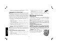
1. Open the guard latch (H), and align
H
the lugs with slots on the gear case
cover. Position the guard facing
backward, as shown.
2. Push the guard down until the guard
lugs engage and rotate freely in the
groove on the gear case hub.
3. With the guard latch open, rotate the
guard into the desired working position
that provides maximum protection to
the user as shown.
4. Close the guard latch to secure the
guard on the gear case. You should
be unable to rotate the guard by
hand when the latch is closed. Do not
operate the grinder with a loose guard or the clamp lever in open
position.
5. To remove the guard, follow the procedure above in reverse order.
NOTE: The guard is pre-adjusted to the
I
diameter of the gear case hub at the
factory. If, after a period of time, the guard
becomes loose, tighten the adjusting screw
(I) with clamp in the closed position.
CAUTION: Do not tighten the adjusting
screw with the clamp lever in open position.
Undetectable damage to the guard or the
mounting hub may result.
MOUNTING AND REMOVING HUBBED WHEELS
Hubbed wheels install directly on the 5/8"– 11 or M14 threaded
spindle.
1. Thread the wheel on the spindle by hand, seating the wheel
against the soft mount.
2. Depress the spindle lock button and use a wrench to tighten the
hub of the wheel.
3. Reverse the above procedure to remove the wheel.
CAUTION: Failure to properly seat the wheel against the soft
mount before turning the tool on may result in damage to the tool or
the wheel.
MOUNTING NON-HUBBED WHEELS
Depressed center, Type 27 grinding wheels must be used with
available accessory flanges. See the chart on pages 27–29 of this
manual for more information.
1. Install the metal backing flange (J) on spindle
J
E
(E) against the soft mount.
2. Place wheel against the backing flange,
centering the wheel on the backing flange
pilot.
3. While depressing the spindle lock button,
K
thread the clamp nut (K) on spindle, piloting
the raised hub on clamp nut in the center of
grinding wheel.
4. Tighten the clamp nut with a wrench.
5. Reverse the above procedure to remove
the wheel.
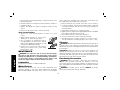
SURFACE GRINDING WITH GRINDING WHEELS
1. Allow the tool to reach full speed before touching tool to work
surface.
2. Apply minimum pressure to work surface, to allow the tool to
operate at high speed.
3. Maintain a 20˚ to 30˚ angle between the tool and work surface.
4. Continuously move the tool in a forward
20˚- 30˚
and back motion to avoid creating gouges
in the work surface.

32
English
5. Remove the tool from work surface before turning tool off. Allow
the tool to stop rotating before setting it down.
EDGE GRINDING WITH GRINDING WHEELS
CAUTION: Wheels used for cutting and edge grinding may break
if they bend or twist while the tool is being used to do cut-off work
or deep grinding. To reduce the risk of serious injury, limit the use of
these wheels with a standard type 27 guard to shallow cutting and
notching (less than 1/2” in depth). The open side of the guard must
be positioned away from the operator. For deeper cutting with a type
1 wheel, use a closed, type 1 guard. Type 1 guards are available at
extra cost from your local dealer or authorized service center.
1. Allow the tool to reach full speed before touching the tool to the
work surface.
2. Apply minimum pressure to work surface, to allow the tool to
operate at high speed.
3. Protect yourself during edge finishing by directing the open side
of the guard away from you.
4. Move the tool continuously in a forward and back motion to avoid
creating gouges in the work surface.
5. Remove tool from work surface before turning the tool off. Allow
the tool to stop rotating before setting it down.
WARNING: Do not use edge grinding wheels for surface grinding
applications because edge grinding wheels are not designed for side
pressures encountered with surface grinding. Wheel breakage and
injury may result.
SURFACE FINISHING WITH SANDING FLAP DISCS
1. Allow the tool to reach full speed before touching tool to work
surface.
2. Apply minimum pressure to work surface, to allow the tool to
operate at high speed.
3. Maintain a 5˚ to 10˚ angle between the tool and work surface.
4. Continuously move the tool in a forward
5˚- 10˚
and back motion to avoid creating gouges
in the work surface.
5. Remove the tool from work surface before
turning tool off. Allow the tool to stop rotating before setting it
down.
Mounting and Using Sanding
Backing Pads
Sanding pads and sanding discs must be rated above minimum
accessory speed as shown on tool. Recommended sanding backing
pads and sanding discs are available at extra cost from D
EWALT
service centers and D
EWALT dealers.
NOTE : Guard may be removed for sanding applications with backing
pads and sanding discs. Sanding flap discs are considered grinding
wheels by ANSI standards and require the use of a guard. (See
Mounting and Using Depressed Center Grinding Wheels and
Sanding Flap Discs).
MOUNTING SANDING BACKING PADS
WARNING: To reduce the risk of serious personal injury,
turn tool off and disconnect tool from power source before
making any adjustments or removing/installing attachments
or accessories. Before reconnecting the tool, depress and
release the trigger switch to ensure that the tool is off. An
accidental start-up can cause injury.
CAUTION: Proper guard must be
N
L
reinstalled for grinding wheel, sanding flap
disc, wire brush, or wire wheel applications
after sanding applications are complete.

33
English
1. Place or appropriately thread rubber backing pad (L) down to
mount.
2. Place the sanding disc on the rubber backing pad.
3. While depressing spindle lock, thread clamp nut (N) on spindle,
piloting the raised hub on the clamp nut into the center of sanding
disc and backing pad.
4. Tighten the clamp nut with the proper wrench.
5. To remove the wheel, reverse the above procedure.
USING SANDING BACKING PADS
Choose the proper grit sandpaper for your application. Sandpaper
is available in various grits. Coarse grits yield faster material removal
rates and a rougher finish. Finer grits yield slower material removal and
a smoother finish. Begin with coarser grit discs for fast, rough material
removal. Move to a medium grit paper and finish with a fine grit disc
for optimal finish.
Coarse 16 - 30 grit
Medium 36 - 80 grit
Fine Finishing 100 - 120 grit
Very Fine Finishing 150 – 180 grit
1. Allow the tool to reach full speed before touching tool to work
surface.
2. Apply minimum pressure to work surface, allowing tool to operate
at high speed.
3. Maintain a 5˚ to 15˚ angle between the tool and work surface.
The sanding disc should contact approximately one inch of work
surface.
4. Move the tool constantly in a straight line to prevent burning and
swirling of work surface. Allowing the tool to rest on the work
surface without moving, or moving the tool in a circular motion
causes burning and swirling marks on the work surface.
5. Remove the tool from the work surface before turning the tool off.
Allow the tool to stop rotating before setting it down.
Mounting and Using Wire Brushes and
Wire Wheels
WARNING: To reduce the risk of serious personal injury,
turn tool off and disconnect tool from power source before
making any adjustments or removing/installing attachments
or accessories. Before reconnecting the tool, depress and
release the trigger switch to ensure that the tool is off. An
accidental start-up can cause injury.
Wire brushes and wire wheels must be rated above minimum
accessory speed as shown on tool. Use only wire brushes and
wheels provided with a 5/8"–11 or M-14 threaded hub. A type 27
guard is required when using wire brushes and wheels.
CAUTION: Wear work gloves when handling wire brushes or
wheels. Wire brushes and wheels can become sharp.
MOUNTING WIRE BRUSHES AND WIRE WHEELS
1. Thread the wheel on the spindle by hand, seating the wheel
against the mount.
2. Depress the spindle lock button and use a wrench on the hub of
the wire brush or wheel to tighten the wheel.
3. To remove the wheel, depress the spindle lock button and use a
wrench on the hub of the wire brush or wheel to loosen it.
NOTE: Failure to properly seat the wheel hub against the mount
before turning the tool on may result in damage to the tool or wheel.
USING WIRE CUP BRUSHES AND WIRE WHEELS
Wire wheels and brushes can be used for removing rust, scale and
paint, and for smoothing irregular surfaces.
1. Allow tool to reach full speed before touching tool to work
surface.
2. Apply minimum pressure to work surface, to allow the tool to
operate at high speed.

34
English
3. Maintain a 5˚ to 10˚ angle between the tool and
5˚-10˚
work surface for wire cup brushes.
4. Maintain contact between the edge of the
wheel and the work surface with wire wheels.
5. Continuously move the tool in a forward and
back motion to avoid creating gouges in the
work surface. Allowing the tool to rest on
the work surface without moving, or moving
the tool in a circular motion causes burning
and swirling marks on the work surface.
6. Remove the tool from the work surface
before turning the tool off. Allow the tool to
stop rotating before setting it down.
Mounting and Using Flaring Cup
(Type 11) Wheel
MOUNTING FLARING CUP WHEEL GUARD
WARNING: The flaring cup wheel guard is not included with
this tool. Flaring cup wheels require proper flanges and guards. 4"
(102mm) flaring cup wheel guard and 6" (152 mm) flaring cup wheel
guard are available as accessories and include proper flange. Failure
to use the proper flange and guard can result in injury resulting from
wheel breakage and wheel contact.
WARNING: To reduce the risk of serious personal injury,
turn tool off and disconnect tool from power source before
making any adjustments or removing/installing attachments
or accessories. Before reconnecting the tool, depress and
release the trigger switch to ensure that the tool is off. An
accidental start-up can cause injury.
1. Install the guard as shown.
2. Guard body should be positioned between the spindle and the
operator to provide maximum operator protection.
3. Securely tighten the two clamping
W
screws (W) supplied with the guard.
MOUNTING FLARING CUP WHEEL
1. Remove the mount (F).
2. Install the flaring cup wheel backing
flange, aligning the flats (O) on spindle
with the flats on backing flange (P).
P
O
F
3. Thread the flaring cup wheel on spindle by hand, seating wheel
against backing flange.
4. Depress the spindle lock button and tighten the wheel by hand.
5. To remove the wheel, reverse the above procedure.
CAUTION: Failure to properly seat the wheel against backing
flange before turning the tool on may result in damage to the tool or
the wheel.
NOTE: Adjust the guard skirt so that only 1/8" (3mm) of the wheel is
exposed below the skirt.
USING A FLARING CUP WHEEL
Flaring cup wheels are designed for heavy material removal.
1. Allow the tool to reach full speed before touching tool to work
surface.
2. Apply minimum pressure to work surface, allowing the tool to
operate at high speed.

35
English
3. Maintain a 5˚ to 10˚ angle between the tool
5˚-10˚
and the work surface.
4. Continuously move the tool in a forward and
back motion to avoid creating gouges in the
work surface.
5. Remove the tool from work surface before turning tool off. Allow
the tool to stop rotating before setting it down.
Mounting and Using Cutting
(Type 1) Wheels
Cutting wheels include diamond wheels and abrasive discs. Abrasive
cutting wheels for metal and concrete use are available. Diamond
blades for concrete cutting can also be used.
WARNING: A closed, cutting wheel guard is not included with
this tool. Cutting wheels require proper flanges and guards. A 7"
(180 mm) cutting guard, is available as an accessory and includes
proper, matching flanges. Failure to use proper flange and guard can
result in injury resulting from wheel breakage and wheel contact.
MOUNTING CLOSED (TYPE 1) GUARD
WARNING: To reduce the risk of serious personal injury,
turn tool off and disconnect tool from power source before
making any adjustments or removing/installing attachments
or accessories. Before reconnecting the tool, depress and
release the trigger switch to ensure that the tool is off. An
accidental start-up can cause injury.
1. Open the guard latch (H), and align the lugs
H
with slots on the gear case cover. Position
the guard facing backward, as shown.
2. Push the guard down until the guard lug
engages and rotates freely in the groove on
the gear case hub.
3. Rotate guard (Q) into desired working position. The guard body
should be positioned between the spindle and the operator to
provide maximum operator protection.
Q
I
4. Close the guard latch to secure the guard on the gear case cover.
You should be unable to rotate the guard by hand when the latch
is in closed position. Do not operate grinder with a loose guard or
clamp lever in open position.
NOTE: The guard is pre-adjusted to the dia met er of the gear case
hub at the factory. If, after a period of time, the guard be comes loose,
tighten the adjusting screw (I) with the clamp lever in the closed
position.
CAUTION: Do not tighten adjusting screw with clamp lever in
open position. Undetectable damage to guard or mounting hub may
result.
MOUNTING CUTTING WHEELS
1. Remove soft mount (F).
2. Install wheel backing flange, aligning flats on spindle (O) with flats
on backing flange (R).
F
O
R

36
English
3. Place the wheel on the backing flange, centering the wheel on the
backing flange pilot.
4. Install the clamp nut, ensuring that the wheel remains centered on
the backing flange.
5. Depress the spindle lock button and tighten clamp nut with
wrench.
6. Reverse the above procedure to remove the wheel.
USING CUTTING WHEELS
1. Allow tool to reach full speed before touching tool to work
surface.
2. Apply minimum pressure to work surface,
allowing tool to operate at high speed.
3. Once you begin a cut, maintain the angle of
the cutting wheel to the work surface. This will
keep you from bending the wheel which could
result in wheel breakage and injury.
4. Remove the tool from work surface before
turning tool off. Allow the tool to stop rotating
before setting it down.
MAINTENANCE
WARNING: To reduce the risk of serious personal injury,
turn tool off and disconnect tool from power source before
making any adjustments or removing/installing attachments
or accessories. Before reconnecting the tool, depress and
release the trigger switch to ensure that the tool is off.
Lubrication
Your power tool requires no additional lubrication.
Motor Brushes
When brushes become worn, the tool will automatically stop,
preventing damage to the motor. Brush replacement should be
performed by D
EWALT authorized service centers or other qualified
service personnel. Qualified service personnel should follow the
procedures below when replacing motor brushes.
1. Remove the brush doors located on the sides of motor housing.
2. To remove the brush, hold the female terminal, which is attached
to the brush lead wire, and disconnect the female terminal from
the male terminal.
3. Pull the brush straight up out of the brush holder.
4. Replace brushes, in pairs, with original D
EWALT brushes available
from D
EWALT authorized service centers.
5. Ensure that the brushes slide freely in brush box.
6. Reconnect the brush lead wire to brush box terminal.
7. Reinstall the brush doors before using the tool. Torque screws to
10 in-lbs, maximum. Overtightening may cause screws to strip.
Cleaning
WARNING: Blow dirt and dust out of the main housing with dry air
as often as dirt is seen collecting in and around the air vents. Wear
approved eye protection and approved dust mask when performing
this procedure.
WARNING: Never use solvents or other harsh chemicals for
cleaning the non-metallic parts of the tool. These chemicals may
weaken the materials used in these parts. Use a cloth dampened only
with water and mild soap. Never let any liquid get inside the tool;
never immerse any part of the tool into a liquid.
Purchasing Accessories
WARNING: Since accessories, other than those offered by
D
EWALT, have not been tested with this product, use of such
accessories with this tool could be hazardous. To reduce the risk of
injury, only D
EWALT, recommended accessories should be used with
this product.
WARNING: To reduce the risk of injury, ALWAYS use proper
guards when grinding and wear eye protection.

37
English
Repairs
The charger and battery pack are not serviceable.
To assure product SAFETY and RELIABILITY, repairs, maintenance
and adjustment (including brush inspection and replacement) should
be performed by authorized service centers or other qualified service
personnel, always using identical replacement parts.
Protecting the Environment
Separate collection. This product must not be disposed of
with normal household waste.
Should you find one day that your D
EWALT product needs
replacement, or if it is of no further use to you, do not dispose of it
with household waste.
Separate collection of used products and packaging allows
materials to be recycled and used again. Re-use of recycled
materials helps prevent environmental pollution and reduces
the demand for raw materials.
Local regulations may provide for separate collection of electrical
products from the household, at municipal waste sites or by the
retailer when you purchase a new product.
D
EWALT provides a facility for the collection and recycling of DEWALT
products once they have reached the end of their working life. To take
advantage of this service please return your product to any authorized
service center that will collect them on our behalf.
You can check the location of your nearest authorized service center
by contacting your local D
EWALT office. Alternatively, a service center
listing is included in the packaging of this product.
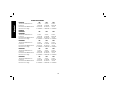
SPECIFICATIONS
D28493P B3 B2 AR
Voltage 120V~ 220V~ 220V~
Watts 2400 W 2400 W 2400 W
Frequency 50-60 Hz 50-60 Hz 50 Hz
No-load rotation 5000/min 5000/min 5000/min
D284076
D28494W
D28494M
B3 B2 AR
Voltage 120V~ 220V~ 220V~
Watts 2400 W 2400 W 2400 W
Frequency 50-60 Hz 50-60 Hz 50 Hz
No-load rotation 6500/min 6500/min 6500/min
D28496M B3 B2 AR
Voltage 120V~ 220V~ 220V~
Watts 2700 W 2700 W 2700 W
Frequency 50-60 Hz 50-60 Hz 50 Hz
No-load rotation 6500/min 6500/min 6500/min
D28474W B3 B2 AR
Voltage 120V~ 220V~ 220V~
Watts 2400 W 2400 W 2400 W
Frequency 50-60 Hz 50-60 Hz 50 Hz
No-load rotation 8500/min 8500/min 8500/min
D28476W B3 B2 AR
Voltage 120V~ 220V~ 220V~
Watts 2700 W 2700 W 2700 W
Frequency 50-60 Hz 50-60 Hz 50 Hz
No-load rotation 8500/min 8500/min 8500/min

DEWALT Industrial Tool Co., 701 East Joppa Road, Baltimore, MD 21286
(NOV11) Part No. N142596 D28474, D28476, D28494, D28496, D284076, D28493
Copyright @ 2002, 2005, 2006, 2011 D
EWALT
The following are trademarks for one or more D
EWALT power tools: the yellow and black color scheme; the “D” shaped air intake grill; the
array of pyramids on the handgrip; the kit box configuration; and the array of lozenge-shaped humps on the surface of the tool.
SOLAMENTE PARA PROPÓSITO DE ARGENTINA:
IMPORTADO POR: BLACK & DECKER ARGENTINA S.A.
PACHECO TRADE CENTER
COLECTORA ESTE DE RUTA PANAMERICANA
KM. 32.0 EL TALAR DE PACHECO
PARTIDO DE TIGRE
BUENOS AIRES (B1618FBQ)
REPÚBLICA DE ARGENTINA
NO. DE IMPORTADOR: 1146/66
SOLAMENTE PARA PROPÓSITO DE MÉXICO:
IMPORTADO POR: BLACK & DECKER S.A. DE C.V.
BOSQUES DE CIDROS, ACCESO RADIATAS NO.42
3A. SECCIÓN DE BOSQUES DE LAS LOMAS
DELEGACIÓN CUAJIMALPA,
05120, MÉXICO, D.F.
TEL. (52) 555-326-7100
R.F.C.: BDE810626-1W7
HECHO EN CHINA
MADE IN CHINA
MAQUINAS Y HERRAMIENTAS BLACK & DECKER CHILE S.A.
AVDA. EDUARDO FREI M. #6001 EDIFICIO 67
CONCHALI-SANTIAGO
CHILE
-
 1
1
-
 2
2
-
 3
3
-
 4
4
-
 5
5
-
 6
6
-
 7
7
-
 8
8
-
 9
9
-
 10
10
-
 11
11
-
 12
12
-
 13
13
-
 14
14
-
 15
15
-
 16
16
-
 17
17
-
 18
18
-
 19
19
-
 20
20
-
 21
21
-
 22
22
-
 23
23
-
 24
24
-
 25
25
-
 26
26
-
 27
27
-
 28
28
-
 29
29
-
 30
30
-
 31
31
-
 32
32
-
 33
33
-
 34
34
-
 35
35
-
 36
36
-
 37
37
-
 38
38
-
 39
39
-
 40
40


Ask a question and I''ll find the answer in the document
Finding information in a document is now easier with AI
in other languages
- español: DeWalt D28474W Manual de usuario
Related papers
Other documents
-
Porter-Cable PC750AG User manual
-
Black & Decker BDGL2223 User manual
-
Bosch 1600A0014V Datasheet
-
-
Craftsman 900.24542 User manual
-
-
Bostitch BTE820K User manual
-
-
Black & Decker KG115 User manual
-
Black & Decker BEG010 User manual