Page is loading ...

PDP4210EA
Model:
SERVICE MANUAL
Safety Precaution
Technical Specifications
Block Diagram
Circuit Diagram
Basic Operations & Circuit Description
Main IC Specifications
Product Specification of PDP Module
Trouble Shooting Manual of PDP Module
Spare Part List
Exploded View
If you forget your V-Chip Password
Software Upgrade
This manual is the latest at the time of printing, and does not
include the modification which may be made after the printing,
by the constant improvement of product.

Safety Precaution
PRECAUTIONS DURING
SERVICING
1. In addition to safety, other parts and
assemblies are specified for conformance with
such regulations as those applying to spurious
radiation. These must also be replaced only
with specified replacements.
Examples: RF converters, tuner units, antenna
selection switches, RF cables, noise-blocking
capacitors, noise-blocking filters, etc.
2. Use specified internal Wiring. Note especially:
1) Wires covered with PVC tubing
2) Double insulated wires
3) High voltage leads
3. Use specified insulating materials for hazardous
live parts. Note especially:
1) Insulating Tape
2) PVC tubing
3) Spacers (insulating barriers)
4) Insulating sheets for transistors
5) Plastic screws for fixing micro switches
4. When replacing AC primary side components
(transformers, power cords, noise blocking
capacitors, etc.), wrap ends of wires securely
about the terminals before soldering.
5. Make sure that wires do not contact heat
generating parts (heat sinks, oxide metal film
resistors, fusible resistors, etc.)
6. Check if replaced wires do not contact sharply
edged or pointed parts.
7. Make sure that foreign objects (screws, solder
droplets, etc.) do not remain inside the set.
The lightning flash with arrowhead symbol,
within an equilateral triangle, is intended to
alert the user to the presence of uninsulated
“dangerous voltage” within the product’s enclo
sure that may be of sufficient magnitude to
constitute a risk of electric shock to persons.
The exclamation point within an equilateral
triangle is intended to alert the user to the
presence of important operating and
maintenance (servicing) instructions in the
literature accompanying the appliance.
CAUTION: TO REDUCE THE RISK OF
ELECTRIC SHOCK, DO NOT REMOVE COVER
(OR BACK). NO USER-SERVICEABLE PARTS
INSIDE. REFER SERVICING TO QUALIFIED
SERVICE PERSONNEL ONLY.
CAUTION
RISK OF ELECTRIC SHOCK
DO NOT OPEN
MAKE YOUR CONTRIBUTION
TO PROTECT THE
ENVIRONMENT
Used batteries with the ISO symbol
for recycling as well as small accumulators
(rechargeable batteries), mini-batteries (cells) and
starter batteries should not be thrown into the
garbage can.
Please leave them at an appropriate depot.
WARNING:
Before servicing this TV receiver, read the
SAFETY INSTRUCTION and PRODUCT
SAFETY NOTICE.
SAFETY INSTRUCTION
The service should not be attempted by anyone
unfamiliar with the necessary instructions on this
apparatus. The following are the necessary
instructions to be observed before servicing.
1. An isolation transformer should be connected in
the power line between the receiver and the
AC line when a service is performed on the
primary of the converter transformer of the set.
2. Comply with all caution and safety related
provided on the back of the cabinet, inside the
cabinet, on the chassis or picture tube.
3. To avoid a shock hazard, always discharge the
picture tube's anode to the chassis ground
before removing the anode cap.
4. Completely discharge the high potential voltage
of the picture tube before handling. The picture
tube is a vacuum and if broken, the glass will
explode.

PRODUCT SAFETY NOTICE
Many electrical and mechanical parts in this
apparatus have special safety-related
characteristics.
These characteristics are offer passed
unnoticed by visual spection and the protection
afforded by them cannot necessarily be obtained
by using replacement components rates for a
higher voltage, wattage, etc.
The replacement parts which have these
special safety characteristics are identified by
marks on the schematic diagram and on the parts
list.
Before replacing any of these components,
read the parts list in this manual carefully. The
use of substitute replacement parts which do not
have the same safety characteristics as specified
in the parts list may create shock, fire, or other
hazards.
9. Must be sure that the ground wire of the AC
inlet is connected with the ground of the
apparatus properly.
5. When replacing a MAIN PCB in the cabinet,
always be certain that all protective are
installed properly such as control knobs,
adjustment covers or shields, barriers, isolation
resistor networks etc.
6. When servicing is required, observe the original
lead dressing. Extra precaution should be given
to assure correct lead dressing in the high
voltage area.
7. Keep wires away from high voltage or high
tempera ture components.
8. Before returning the set to the customer,
always perform an AC leakage current check
on the exposed metallic parts of the cabinet,
such as antennas, terminals, screwheads,metal
overlay, control shafts, etc., to be sure the set
is safe to operate without danger of electrical
shock. Plug the AC line cord directly to the
AC outlet (do not use a line isolation
transformer during this check). Use an AC
voltmeter having 5K ohms volt sensitivity or
more in the following manner.
Connect a 1.5K ohm 10 watt resistor paralleled
by a 0.15µF AC type capacitor, between a
good earth ground (water pipe, conductor etc.,)
and the exposed metallic parts, one at a time.
Measure the AC voltage across the combination
of the 1.5K ohm resistor and 0.15 uF
capacitor. Reverse the AC plug at the AC
outlet and repeat the AC voltage measurements
for each exposed metallic part.
The measured voltage must not exceed 0.3V
RMS.
This corresponds to 0.5mA AC. Any value
exceeding this limit constitutes a potential
shock hazard and must be corrected
immediately.
The resistance measurement should be done
between accessible exposed metal parts and
power cord plug prongs with the power switch
"ON". The resistance should be more than
6M ohms.
Good earth ground
such as the water
pipe, conductor,
etc.
Place this probe
on each exposed
metallic part
AC VOLTMETER
AC Leakage Current Check

Technical Specifications
MODEL : PDP4210EA
42” Plasma Display
DATE FIRST ISSUED
ISSUE
1
RAISED BY
CHECKED BY
NUMBER OF PAGES
10
REVISIONS
ISSUED DATE DESCRIPTION RAISED BY :
SPECIFICATION AGREED : SIGNATURE DATE
R & D DEPARTMENT
COMMERCIAL DEPARTMENT
PRODUCTION DEPARTMENT
Q/A DEPARTMENT
CUSTOMER
......................................................................................
......
......................................................................................
......
......................................................................................
.......
......................................................................................
.......
......................................................................................
.......
...........................
...
...........................
...
...........................
...
...........................
...
...........................
...
SPECIFICATION APPROVED :
.
SIGNATURE :
DATE :
NOTE :
Only documents stamped “Controlled Document” to be used for manufacture of production parts.

Technical Specifications
PDP4210EA
CONTINUATION PAGE
NUMBER
2 OF 10 PAGES
1. Standard Test Conditions
All tests shall be performed under the following conditions, unless otherwise specified.
1.1 Ambient light : 150ux (When measuring I
B
, the ambient luminance
≦0.1Cd/m
2
)
1.2 Viewing distance : 50cm in front of PDP
1.3 Warm up time : 30 minutes
1.4 PDP Panel facing : no restricted
1.5 Measuring Equipment : PC, Chroma 2225 signal generator (with Chroma digital
additional card) or equivalent, Minolta CA100 photometer
1.6 Magnetic field
: no restricted
1.7 Control settings : Brightness, Contrast, Tint, Color set at Center(50)
1.8 Power input : 110~120Vac,60Hz
1.9 Ambient temperature : 20°C ± 5°C (68°F ± 9°F)
1.10 Display mode : 31.5KHz/60Hz (Resolution 852 x 480)
1.11 Other conditions :
1.11.1 With image sticking protection of PDP module, the luminance will descend
by time on a same still screen and rapidly go down in 5 minutes. When
measuring the color tracking and luminance of a same still screen, be sure
to accomplish the measurement in one minute to ensure its accuracy.
1.11.2 Due to the structure of PDP, the extra-high-bright same screen should not
hold over 5 minutes for fear of branding on the panel.

Technical Specifications
PDP4210EA
CONTINUATION PAGE
NUMBER
3 OF 10 PAGES
ELECTRICAL CHARACTERISTICS
2. Power Input
2.1 Voltage : 110 ~120VAC
2.2 Input Current : 3.5A
2.3 Maximum Inrush Current : <30 A (FOR AC110V ONLY)
Test condition : Measured when switched off for at least 20 mins
2.4 Frequency : 60Hz(±3Hz)
2.5 Power Consumption : ≤ 330W
Test condition : full white display with maximum brightness and
contrast
2.6 Power Factor : Meets IEC1000-3-2
2.7 Withstanding voltage : 1.5kVac or 2.2kVdc for 1 sec
3. Display
3.1 Screen Size : 42” Plasma display
3.2 Aspect Ratio : 16:9
3.3 Pixel Resolution : 852x480
3.4 Peak Brightness : 1000 cd/m² (Panel module without filter)
3.5 Contrast Ratio (Dark room) : 3000:1 (Panel module without filter)
3.6 Viewing Angle : Over 160°
3.7 OSD language : English,Spaish,French
4. Signal
4.1 AV & Graphic input
4.1.1 TV standard : NTSC/ATSC
4.1.2 TV Tuning system : 181CH (for NTSC), 2~69CH (for ATSC)
4.1.3 CATV : 125CH (for NTSC)
4.1.4 Composite signal : AV
4.1.5 Y,C Signal : S-Video
4.1.6 Component signal : Y, Pb/Cb, Pr/Cr, HDTV compatible
4.1.7 Graphic I/P : Analog: D-sub 15pin detachable cable
Digital: DVI
4.1.8 PnP compatibility : DDC 1.0
4.1.9 I/P frequency : f
H
: 31.5kHz to 60kHz/f
V
: 56.25Hz to 75Hz (640x480
recommended)

Technical Specifications
PDP4210EA
CONTINUATION PAGE
NUMBER
4 OF 10 PAGES
4.2 Audio input
Audio I/P(L/Rx5) : 1 for DVI
1 for D-Sub
2 for YPbPr
1 for S-Video /AV
4.3 Audio output
Audio O/P(L/Rx1) : Monitor out(L/R)
SPDIF : Optical x 1
5. Environment
5.1 Operating environment
5.1.1 Temperature : 5º to 33°C
5.1.2 Relative humidity: 20% to 85%(non-condensing)
5.2 Storage and Transport
5.2.1 Temperature : -20°C to 60°C(-4º to 140°F)
5.2.2 Relative humidity: 5% to 95%
6. Panel Characteristics
6.1 Type : LG V6
6.2 Size : 42”, 1005mm(width)x597mm(height)x61mm(depth)±1
mm)
6.3 Aspect ratio : 16:9
6.4 Viewing angle : Over 160°
6.5 Resolution : 852x480
6.6 Weight : 14.8kg ±0.5 kg (Net)
6.7 Color : 16.77 million colors by combination of 8 bits R,G,B digital
6.8 Contrast : Average 60:1 (In a bright room with 150Lux at center)
Typical 3000:1 (In a dark room 1/25 White Window
pattern at center).
6.9 Peak brightness : Typical 1000cd/㎡ (1/25 White Window)
6.10 Color Coordinate Uniformity : Contrast; Brightness and Color control
at normal setting
Test Pattern : Full white pattern
Average of point A,B,C,D and E +/- 0.01

Technical Specifications
PDP4210EA
CONTINUATION PAGE
NUMBER
5 OF 10 PAGES
6.11 Color temperature : Contrast at center (50); Brightness center (50);
Color temperature set at Natural
x=0.285±0.02
y=0.293±0.02
6.12 Cell Defect Specifications
Subject to Panel supplier specification as appends.
7. Front Panel Control Button
7.1 CH Up / Down Button : Push the key to changing the channel up or down.
When selecting the item on OSD menu.
Volume Up/ Down Button : Push the key to increase the volume up or down.
When selecting the adjusting item on OSD menu
increase or decrease the data-bar.
Menu Button : Enter to the OSD menu.
Input Select Button : Push the key to select the input signals source.
7.2 Stand by Button : Switch on main power, or switch off to enter power
Saving modes.
7.3 Main Power Switch : Turn on or off the unit.
8. OSD Function
Full on screen display

Technical Specifications
PDP4210EA
CONTINUATION PAGE
NUMBER
6 OF 10 PAGES
9. Agency Approvals
Safety UL60950
Emissions FCC class B
10. Reliability
11.1 MTBF : 20,000 hours(Use moving picture signal at 25°C ambient)
11. Accessories : User manual x1, Remote control x1, Stand x1, Power cord x1,
Battery x 2.
Technical Specifications
PDP4210EA
CONTINUATION PAGE
NUMBER
6

13. Support the Signal Mode
A. VGA and DVI mode
B. HDTV Mode (YPbPr)
- When the signal received by the Display exceeds the allowed range, a warning message
“Main Not Support!” shall appear on the screen.
- You can confirm the input signal format from the on-screen.
NO. Resolution
Horizontal
Frequency
(KHz)
Vertical
Frequency
(Hz)
Dot Clock
Frequency
(MHz)
1 640 x 400 31.47 70.08 25.17
2 640 x 480 31.50 60.00 25.18
3 640 x 480 37.50 75.00 31.50
4 640 x 480 37.86 72.81 31.50
5 720 x 400 31.47 70.08 28.32
6 800 x 600 35.16 56.25 36.00
7 800 x 600 37.90 60.32 40.00
8 800 x 600 46.90 75.00 49.50
9 800 x 600 48.08 72.19 50.00
10 832 x 624 49.00 75.00 57.27
11
1024 x 768 48.40 60.00 65.00
12 1024 x 768 56.50 70.00 75.00
13 1024 x 768 60.00 75.00 78.75
14 1152 x 864 63.86 70.02 94.51
15 1152 x 864 67.52 75.02 108.03
16 1280 x 720 45.00 60.00 74.25
17 1280 x 960 60.02 60.02 108.04
18 1280 x 1024 64.00 60.01 108.00
NO. Resolution
Horizontal
Frequency
(KHz)
Vertical
Frequency
(Hz)
Dot Clock
Frequency
(MHz)
1 480i 15.734 59.94 13.50
2 480p(720x480) 31.468 59.94 27.00
3 576p(720x576) 31.25 50.00 27.00
4 720p(1280x720) 37.50 50.00 74.25
5 720p(1280x720) 45.00 60.00 74.25
6 1080i(1920x1080) 33.75 60.00 74.25
Technical Specifications
PDP4210EA
CONTINUATION PAGE
NUMBER
6 OF 9 PAGES
OF 10 PAGES
Technical Specifications
PDP4210EA
CONTINUATION PAGE
NUMBER
7

Remote Control
Standby ( ): Press to turn on and off.
Mute ( ): Press to mute the sound.
Press again to restore the sound.
0~9 Number Buttons: Press 0~9 to
select a channel, and used to input the
password; the channel changes
after
2 seconds.
EPG: Press to display EPG mode.
Press it again to exit EPG mode.
Input: Press to select the signal
source, such as TV, AV, S-Video,
Component 1, Component 2, VGA,
DVI or DTV.
DTV: Press to choose DTV directly.
Dot: Press number buttons with it to
select the channels directly in DTV.
VOL +/-: Press to adjust the volume.
CH +/- : Press to select the channel
forward or backward.
MTS: Press repeatedly to cycle through
the Multi-channel TV sound (MTS)
options: Mono, Stereo and SAP
(Second Audio Program).
◄,►,▲,▼, Enter: Press ◄,►,▲,
▼ to move the on-screen cursor. To
select an item, press Enter to confirm.
And it can also press ▲ or ▼ to
select channels, press ◄ or ► to
adjust the volume.
Exit: Press this button to exit.
Menu: Press to enter into the on-screen
setup menu, press again to exit.
V-Chip: Press to select the child
protect mode.
CCD: Press to select the Closed Caption mode.
Freeze: Press to freeze the picture, press again to restore the picture.
Display: Press to display the channel information and it disappear after 3 seconds.
Favorite: Press repeatedly to cycle through the favorite channel list.
Add/Erase: Press to add or delete favorite or dislike channels.
S.Mode: Press repeatedly to cycle through the sound mode: Normal, News, Cinema,
Flat and User.
PIC Size: Press repeatedly to cycle through the picture size that best corresponds your
viewing requirements: Normal, Full, Wide1, Wide2, Wide3, 4:3, No Scale and Panoramic.
(Continued on next page)
Technical Specifications
PDP4210EA
CONTINUATION PAGE
NUMBER
8 OF 10 PAGES

Note: Press CH +/- on the remote control can turn on TV set from standby mode.
Insertion of Batteries:
-
Turn the remote control upside down, press and slide off the battery cover.
-
Insert two 1.5V (AAA) batteries into the compartment, take care to observe the and
markings indicated inside.
-
Replace the cover and slide in reverse until the lock snaps.
P.Mode: Press repeatedly to cycle
through the picture mode: Normal,
V
ivid, Hi-Bright, User and Dark.
System:
Press repeatedly to cycle
through the system options: AUTO,
and NTSC3.58.
Recall: Press to return to previous
channel.
Sleep: Press repeatedly until it
displays the time in minutes (5 Min,
10 Min, 15 Min, 30 Min, 60 Min, 90
Min, 120 Min and, OFF) that you
want the TV to remain on before
shutting off. To cancel sleep time,
press SLEEP repeatedly until sleep
OFF appears.
Red: Press this button to access the
red item or page.
Blue: Press this button to access the
blue item or page.
Green: Press this button to access
the green item or page.
Yellow: Press this button to access
the yellow item or page.
Technical Specifications
PDP4210EA
CONTINUATION PAGE
NUMBER
9
OF 10 PAGES

Technical Specifications
PDP4210EA
CONTINUATION PAGE
NUMBER
10 OF 10 PAGES
PHYSICAL CHARACTERISTICS
14. Power Cord
Length : 1.8m nominal
Type : optional
15. Cabinet
15.1 Color : “Black” colour as defined by colour plaque reference number
15.2 Weight
Net weight : 36.2 kg(with stand) /34.0kg(without stand)
Gross weight : 41.0 kg
15.3 Dimensions(with stand)
Width : 1040 mm
Height : 690 mm
Depth : 290 mm

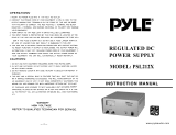
Product Specification of PDP Module
Color Plasma Display Panel
852 X 480 pixels
Address Driver
Scan Driver
Common sustain driver
Display data, Driver timing
Memory
Controller
Driver
Timing
Controller
Input
Interface
Controller
Vcc(+5V)
Va(55V~65V)
Vs(180V~190V)
Control Signal
(Serial Interface)
APL Data
LVDS Input
Applied Voltage level is specified at the time when Full-White pattern is displayed on the panel.
Block Diagram

74HC74
(U12)
UPC3218
AGC Amplifier
(U10)
X6965D
SAW Filter
(U9)
MT5111
DTV Front-end
(U11)
MT5351
DTV Back-end
(U14)
TD1336
Tuner(U8)
256Mb DDR
(U15)
256Mb DDR
(U18)
TS[0...7]
Coaxial
I2C
2nd_IF+ & 2nd_IF-
Differential Data Stream
EEPROM
24C16(U13)
I2C
32Mb
Flash(U17)
Video Data[0...23]
Audio Data
Control
Signals
SPD
Connect with
MT8205
Block Diagram

EEPOROM
24C02(U14)
LP2996
(U12)
IDTQS3VH257
(U25)
IDTQS3
VH257
(U16)
YPbPr
BA7612F
(U23)
EEPROM
24C02(U19)
MT8205
(U7)
CS4334
(U22)
MT8776
(U20)
DDR
128Mb(U11)
Power Connector
(Supplied by PDP)
EEPROM
24C16(U2)
Flash
16M-BIT(U9)
DDR
128Mb(U10)
PDP Connector
SiI161B
(SiI169)
DVI Reciver
(U18)
YpbPr×2
DVI
Video[0...23]
Vedio[0...23]
74LVC244A
U30-U33
Audio
From MT 5351
Control Signals
DVI Audio in
Din
Dout
Bypass Out
Audio L
& Audio R
Audio Bypass
LVDS Data
RGB Output
TV
PDP Control Signals
VGA
I2C (MT8205 I2C)
3.3V
2.5V
1.25V
2.5V
1.25V
5V
5V
5V
3.3V
1.8V
2.5V
3.3V
1.8V
2.5V
1.25V
5V
3.3V
Data[0...31]
Address[0...11]
I2C
MT8205 I2C
I2C
CVBS×2 (CVBS0 is from tuner.)
To PDP
To PDP
MX232A
(U1)
RS232
Signals
TTL Signals
(Used by MT8205)
VGAI2C
DVII2C
AV
V_BYPASS
5V
5V
3.3V
UART0 (Communication with MT5351)
UART2 (MT5351 DownLoad)
From MT3551
YPbPr Audio in
AV Audio in
CD4052
(U17)
AV1 Audio
AV2 Audio
S-Video
Block Diagram

Circuit Diagram
- Power supply board of PDP Module, DGP-420WXGA
- Power supply board of PDP Module, USP490M-42LP
- Main (Video) board
- Audio/Tuner board
- ATSC board
- Keypad board
- Remote control receiver board
- External L/R Speakers board
- Remote control board

5
5
4
4
3
3
2
2
1
1
D D
C C
B B
A A
18 1516
4
1513
2
3
7
17
9
11 1221 819
20
D
HIC_MICOM
6
REVISION HISTORY
NO
1
변경
전
변경
후
일자
/
사유
2004/07/28 FEP30JPPH967C6
<D
<
m
1
R612
12KF
R411 330F
R412 1KF
C403 50V 0.68uF
R504
1.8KF
C225
0.1uF
R132
33KF
PC101
PC-17K1C
R214
360RF
R500
1W 10
D501
SUF30J
C111
0.1uF
R410 330F
R114 3K
TNR101
14D 621K
R416 1KF
0.001uFC204
C101
275VAC 1uF
R700
1W 10
R199
56KF
R414 2KF
D226
LL4148
R210
1W 10F
PC202
CN808
171825-8
1
2
3
4
5
6
7
8
R415 100F
PC-17K1C
PC206
250V 0.47uF
C126
R249
10KF
R176
10KF
R137
10KF
L101
23mH
R408 1KF
1KF
R261
D302
US1M
Q108
KTC3198Y
D503
D10L20U
CN03
3-176976-1
1
2
R143
3W 470K
C116 0.0022uF
45.3KF
R718
R126
75KF
R402 4.7KF
D103
LL4148
C105,106
450V 330uF
L104
CH108200S
D104
US1M
PC102
D5001
SF30SC6
IC300
KA431AZ
R217
10KF
IC501
KIA278R12PI
1 2
3
4
Vin Vo
GND
ON/OFF
R247
1.2K
R229
1W 4.7F
Q202
KRC103M
R301
220F
C410 50V0.01uF
45.3KF
R720
C701,702,704
100V 330uF
J2
0
0R
R508
C516
35V 1000uF
C400
50V 0.1uF
R531
35V 470uF
C117
R518
3.9KF
R115
1.5KF
0.0047uF
C212
Q107
KTC3198Y
R149
100KF
4.7KF
R522
R403 1KF
R609
300KF
R196
56KF
Q702
KTC3207
CN804
171825-9
1
2
3
4
5
6
7
8
9
PC205
R515
1.8KF
R189
200KF
R507
5W 2.7K
C114
0.68uF
R400
1KF
IC502
KIA378R09PI
1 2
3
4
Vin Vo
GND
ON/OFF
KA7552A
IC202
8
1
2
4
3
5
6
7
CS
RT
FB
GND
IS +
OUT
VCC
CT
R155
100KF
R145
2W 240K
KA431AZ
IC500A
2K
VR500
0.047uFC218
C261
4.7uF
C118
0.01uF
R237
5W 0.1
C510
35V 470uF
5K
VR601
CRST400
4MHZ
3
2
1
Xout
GND
Xin
C520
4.7KFR250
R307
5W6.8
R216
100KF
1W 100R
R252
CN806
1-1123723-0
1
2
3
4
5
6
7
8
9
10
L500
6*20 2.5uH
Q208
KTA1281
R120
160KF
C119
0.1uF
R512
15KF
PC204
C406 50V 0.1uF
D105
US1M
SW400
JSS 2209
R117
180KF
C404 50V 0.1uF
R104
10W 0.02
C109
68PF
R222
2.2M
R227
1W 4.7
R423 1KF
R248
100KF
R233
100KF
Q106
KSP2907
C600
1KV 220pF
0.22uFC205 D502
31GF6
CN809
171825-2
1
2
0.001uFC210
R502
0
D200
LL4148
120KF
R627
C514
35V 47uF
SDT-SH-118DM
2W 100K
R602
R501
3.3KF
18KF
R701
R404
1KF
C302
0.68uF
4.7uF
C262
L102
23mH
Q701
KTC3207
R123
330KF
10K
R219
45.3KF
R717
R134
24KF
C113
2.2uF
VA EER4042
T206
R221
2.2M
D300
SB560
D500
SF30SC6
R505
1W 4R7
36KF
R709
R124
220KF
R127
75KF
R706
20KF
D211
1N5234B
R128
75KF
120KF
R604
1KF
R262
CN802
171825-4
1
2
3
4
45.3KF
R721
R133
33KF
270KF
R606
R193
56KF
R516
1KF
R113
24KF
C504,C555~C557
10V 2200uF*4
T208
PFC COIL 200uH
R610
300KF
C407 50V 0.1uF
10KFR251
R102
1W 390KJ
R154
100KF
LED400
GREEN
R305
5W15
120KF
R608
4.7KFR235
R532
1W 2.7K
18KF
R714
R705
20KF
FSF10A60
D600
R224
2.2M
CN02
3-176976-1
1
2
R409 2KF
470pF
C208
R417 1KF
PC206
D106
US1M
C200
630V 0.01uF
R405
1KF
C102,103
250V 0.001uF
C601
1KV 220pF
10uF
C263
D111
1N4148
R407 1KF
Q210
KRC103M
35V 47uFC220
KA7552A
IC201
8
1
2
4
3
5
6
7
CS
RT
FB
GND
IS +
OUT
VCC
CT
BYV26EGP
D205
R112 3KF
C112
330pF
C511
35V 47uF
D303
1N5245B
PC100
PC-17K1C
C227
0.001uF
C409 50V 0.1uF
C405 50V 0.1uF
35V 47uF
C507
10V 2200uF*2
C301,301A
RELAY1
R707
2.7KF
R420 4.7KF
LED401
RED
LL4148
D213
18KF
R708
36KF
R703
R704
22KF
R110
10KF
R175
0
45.3KF
R716
D208
BYV26EGP
3.3KF
R509
F101
250VAC 8A
R148
100KF
Q200
KTA1281
R136
10KF
18KF
R615
R144
10F
35V 47uF
C120
R153
100KF
R306
5W6.8
C202 35V 47uF
35V 47uFC215
1uFC203
CN801
171825-7
1
2
3
4
5
6
7
R125
75KF
R406
1KF
C408 50V 0.1uF
SPW20N60C3*3
Q102,Q103,Q109
R603
1W4R7
10KFR236
LL4148
D204
C110
470pF
PC201 PC-17K1C
Q209
SPW11N80C3
120KF
R613
C222
630V 0.1uF
C104
630V 1uF
630V 0.047uF
C206
R519
1.5KF
Q206
KTA1281
1W 47R
R243
D102
FEP30JP
R150
100KF
C550~C554
10V 2200uF*5
R526
2W 100K
R620
IC400
KIA7045AP
3
2
1
OUT
GND
VCC
TNR102
14D 621K
PC-17K1C
PC202
R401 1KF
R212
10KF
120KF
R628
C214
0.01uF
R109
1W 4.7
PC100
R513
2.7KF
IC200
KA7552A
8
1
2
4
3
5
6
7
CS
RT
FB
GND
IS +
OUT
VCC
CT
L103
CH108200S
Q105
KTA1281
250V 820uF
C602
C226
0.001uF
D109
1N5236B
R228
1W 4.7
Q203,204
SPW11N80C3*2
1uFC216
R198
56KF
PC-17K1C
PC204
R600
1W4R7
R146
2W 100
C505
1KV 0.001uF
PC101
R514
2KF
U101 UC3854N
1
2
3
4
5
6
7
8
9
10
11
12
13
14
15
16
GND
PK
CA
IS
MO
IA
VO
VR
RE
EN
VS
RS
SS
CT
VC
GT
R142
6.8KF
C221
630V 0.1uF
IC401
HMS87C1304A
6
5
3
4
2
1
7
8
9
10
11
12 13
14
15
16
17
18
19
20
21
22
23
24
RD0
VDD
AN6/RA6
AN6/RA6
AN5/RA5
AN4/RA4
RD1
AN0/AVref/RB0
BUZ/RB1
INT0/RB2
INT1/RB3
PWM0/COMP0/RB4 RD2
RD3
Xin
Xout
|RESET
Vss
RC0
RC1
RA0/EC0
RA1/AN1
RA2/AN2
RA3/AN3
C411
50V0.01uF
Q300
FQP17N40
STBY EE1927
T100
D212
1N5234B
C201
0.01uF
18KF
R710
R118
180KF
FSF10A60
D700
R135
10KF
FSF10A60
D601
Q104
KTC3209
R418 1KF
R106
1W 4.7
L301
27uH
PC201
D202
BYV26EGP
35V 47uF
C123
11KF
R711
50V 10uFC115
CN01
3-176976-2
1
2
R111
100F
130KF
R607
18KF
R719
R103
5W 20
C700
1KV 100pF
R195
56KF
45.3KF
R715
R230
4.7KF
T204,205
VS EER4042
U100
5M0280R-YDTU
1 2
34
GND DRAIN
VCCFB
R302
1.02KF
2W 240K
R226
0.001uFC211
R190
200KF
5K
VR700
R140
7.5KF
R141
4.7KF
R510
5W 1K
SEL
CABLE
35V 470uF
C128
470F
R520
C401
50V 0.1uF
R121
160KF
R131
33KF
Q207
KRC103M
D107
US1M
R422 10KF
R108
5W 15
R130
240KF
Q201
SPW11N80C3
1uF
C530
56KF
R525
C108
680pF
33KF
R702
1uFC209
PC205
PC-17K1C
R152
100KF
R511
15KF
D206
LL4148
C304
50V 4.7uF
MULTI EER4042
T207
0.01uF
C219
BD101
D25XB60
R119
180KF
R611
300KF
2.4KF
R260
D301
US1M
R156
1KF
C500
1KV0.001uF
50V 220uF
C506
4.7KFR218
R231
5W 0.05
R303
1KF
R122
18KF
R421 10KF
R246
5W 0.2
R223
2.2M
CN803
1-171825-2
1
2
3
4
5
6
7
8
9
10
11
12
C519
C213
630V 0.01uF
R116
10KF
R225
1M
R107
1W 4.7
LL4148
D203
LL4148
D209
C121
630V 0.01uF
R151
100KF
R503
1KF
R232
1K
CN805
1-1123723-4
1
3
4
2
0.001uFC217
CN807
1-1123723-8
1
2
3
4
5
6
7
8
18KF
R712
R129
150KF
PC-17K1C
PC102
R245
10KF
R253
2W 240K
D108 1N5236B
1/4W 100R
R220
IC500
KA317
1 2
3
Adj Output
Input
R192
56KF
R209
2W 240K
VS_ON
+5V DET
9VSC
+12V DET
5VCTRL
60VA
RYC
ACD
5VSC
PFC +
RLY_ON
RLY ON
SB5V
ACD OUT
VI
5VCTRL
190VS 5VCTRL
AC DET
VI
60VA
9VSC
190VS
+5VSTBY
VS DET
24V/30V
+30V DET
+9V DET
VS ON
RY ON/OFF
RYC
12VSC
VA DET
VA VCC
PFC ON/OFF
5VSC
5VD
PFC+
MULTI ON/OFF
60VA
PFC+
VA DET
5VD OUT
GND
MULTI VCC
PFC +
+12V /1.0A
GND
+9V DET
+12V DET
9VSC
PFC +
VA VCC
VS DET
190VS
190VS
GND
VA,VS ON/OFF
PFC VCC
VA ON/OFF
60VA
GND
GND
GND
GND
방전CTL
VA
AC-1
PFC+
PFC VCC
AC DET
PFC GND
+5VSTBY
PFC ON/OFF
방전 CTL
GND
VS
+5V DET
5VCTRL
+30V/1.0A (+24V/1.25A)
5VSC
GND
MULTI ON/OFF
+5VCTRL
+30V DET
DGP-420WXGA

USP490M-42LP

A
A
B
B
C
C
D
D
E
E
4 4
3 3
2 2
1 1
SCL
SDA
TxD
INVERTER_PWR
8205UP3_1
PWR_GND
+12V
SCL
SDA
TUNER_12V
TUNER_12V
TXD
RXD
RxD
RSRXD
PCRXD
PCTXD
SYS_PWR
8205UP3_1
PCRXD
PCTXD
RSRXD
RSTXD
RSTXD
INVERTER_PWR
PWR_GND
PWR_GND
GPIO_DVD1
GPIO_DVD1
DV33A URST#
URST#
DV18A
5VSB
5VSB
INVERTER_PWR
VCC
DV33A
+12V
+12V
5VSB
5VSB
5VSB
5VSB
DV33A
5VSB
VCC
+12V
DV18A
SDA 7,10
SCL 7,10
INVERTER_PWR 11
8205UP3_1 3
+12V 7,10,13,14
TUNER_12V 7
TXD 3,13
RXD 3,13
PWR_GND 11
PCTXD 13
RSTXD 6
RSRXD 6
GPIO_DVD1 3
URST# 3
DV18A 2 ,3
PCRXD 13
Title
Size Doc Number R e v
Date: Sheet o f
INDEX
V1.2
C
115Wednesday, October 12, 2005
12.WM8776 & A/V BYPASS
2. LDO
14.PDP INTERFACE
For Tuner
5. DDR MEMORY & FLASH
6. VGA IN & PC AUDIO IN
RS-232
7. VIDEO IN & TUNER IO
3. MT8205E PBGA388
1. INDEX
4. MT8205 ANALOG DECOUPLING
DIGITAL GND
8. AUDIO/VIDEO IN CIRCUIT
9. DVI INPUT
10.LVDS/CRT/TTL OUT
11.BACK LIGHT / KEYPAD
SYSTEM EEPROM
AUIO IN/OUT GND
MT8205E (PBGA388) LCDTV BOARD 4 LAYERS
13.ATSC INTERFACE
From Power board.
8205UP3_1 HIGH :POWER OFF
8205UP3_1 LOW :POWER ON
ANALOG INPUT GND
ADD BY MTK
Add by MTK
Add by MTK
Power down Reset circuit
ADD BY MTK
Q14
2N3904
1
3 2
R337
10k
R6
10k
U2
EEPROM 24C16
SOP8/SMD
NC
1
NC
2
NC
3
GND
4
SDA
5
SCL
6
WP
7
VCC
8
R1
10k
R342
0
+
CE3
47uF/16v
C4
0.1uF
C133
20pF
M2
1
R335
0/NC
R3
10K
R2
4.7k
R341 10
R73 10 /NC
C3 0. 1uF
C132
20pF
M3
1
H4
HOLE/GND
2
2
3
3
4
4
5
5
9
9
8
8
7
7
6
6
1
1
J1
5x1 W/HOUSING
PH5/2.0
1
2
3
4
5
J21
CON10
1
2
3
4
5
6
7
8
9
10
J2
DIP11/P2.54
1
2
3
4
5
6
7
8
9
10
11
C5 0. 1uF
J3
8x1 W/HOUSING
DIP8/W/H/P2.54
1
2
3
4
5
6
7
8
C1 0.1uF
+
CE88
47uF/16v
R4
10K
H1
HOLE/GND
2
2
3
3
4
4
5
5
9
9
8
8
7
7
6
6
1
1
V1
1
L50
FB
BEAD/SMD/1206
L1
FB
BEAD/SMD/0805
D28
1N4148
H3
HOLE/GND
2
2
3
3
4
4
5
5
9
9
8
8
7
7
6
6
1
1
H2
HOLE/GND
2
2
3
3
4
4
5
5
9
9
8
8
7
7
6
6
1
1
V2
1
CB1
0.1uF
CB136
0.1uF
C2 0. 1uF
V3
1
R112
R
R0603/SMD
R5
10k
+
CE2
220uF/16v
C220UF16V/D6H11
M1
1
L44
FB
BEAD/SMD/1206
Q1
2N3904
SOT23/SMD
1
3 2
V4
1
U1
MAX232A
R1IN
13
R2IN
8
T1IN
11
T2IN
10
C+
1
C1-
3
C2+
4
C2-
5
V+
2
V-
6
R1OUT
12
R2OUT
9
T1OUT
14
T2OUT
7
VCC
16
GND
15
R336
0
J4
4x1 W/HOUSING
DIP4/W/H/P2.0
1
2
3
4
+
CE1
220uF/16v
C220UF16V/D6H11
CB2
0.1uF
/