Page is loading ...

Copyright DEWALT
Dansk 1
Deutsch 9
English 18
Español 26
Français 34
Italiano 42
Nederlands 50
Norsk 58
Português65
Suomi 73
Svenska 80
EÏÏËÓÈη 88
Page is loading ...
Page is loading ...
Page is loading ...
Page is loading ...
Page is loading ...
Page is loading ...
Page is loading ...
Page is loading ...
Page is loading ...
Page is loading ...
Page is loading ...
Page is loading ...
Page is loading ...
Page is loading ...
Page is loading ...
Page is loading ...
Page is loading ...
Page is loading ...
Page is loading ...
Page is loading ...
Page is loading ...
Page is loading ...
Page is loading ...

ENGLISH
en - 1 18
ROUTER TABLE DE2000
Congratulations!
You have chosen a DEWALT product. Years of experience, thorough
product development and innovation make DEWALT one of the most
reliable partners for professional Power Tool users.
Table of contents
Technical data en - 1
Manufacturer’s Declaration en - 1
Safety instructions en - 1
Package contents en - 2
Description en - 2
Electrical safety en - 2
Mains plug replacement (U.K. & Ireland only) en - 2
Using an extension cable en - 2
Assembly and adjustment en - 3
General en - 3
DE2011 (option) en - 3
DE2000 en - 5
Instructions for use en - 5
DE2011 (option) en - 6
DE2000 en - 6
Optional accessories en - 7
DE2011 (option) en - 7
DE2000 en - 7
Maintenance en - 8
Guarantee en - 8
Technical data
DE2000
Voltage V 230
ON/OFF-switch no-volt release
Dimensions (w x d) mm 770 x 600
height, without legs mm 350
height, with legs mm 860
Loss of cutting depth due to
the table thickness mm 8
Weight kg 23
Fuses:
Europe 230 V tools 16 Amperes, mains
U.K. & Ireland 230 V tools 13 Amperes, in plugs
The following symbols are used throughout this manual:
Denotes risk of personal injury, loss of life or damage to the
tool in case of non-observance of the instructions in this
manual.
Denotes risk of electric shock.
Refer to the instruction manual of your Power Tool.
Manufacturer’s Declaration
DE2000
DEWALT declares that the attachment mentioned above has been
designed in compliance with 89/392/EEC & 73/23/EEC.
This attachment must not be put into service until it has been established
that the Power Tool to be connected to this attachment is in compliance
with 89/392/EEC (identified by the CE-marking on the Power Tool).
Director Engineering and Product Development
Horst Großmann
DEWALT, Richard-Klinger-Straße 40,
D-65510, Idstein, Germany
Safety instructions
Observe the safety regulations in the instruction manual of the Power
Tool to be fitted to this Combi-Table. Read the following safety
instructions before attempting to operate this product.
Keep these instructions in a safe place!
The attention of UK users is drawn to the “woodworking machines
regulations 1974” and any subsequent amendments.
General
• Always mount the Combi-Table in conformity with the present instructions.
• Keep children away.
• Dress properly. Do not wear loose clothing or jewellery. They can be
caught in moving parts. Preferably wear rubber gloves and non-slip
footwear when working outdoors. Wear protective hair covering to
keep long hair out of the way.
• Do not use the Combi-Table outdoors in the rain or in a damp
environment.
• The Combi-Table must be level and stable at all times.
• Keep the work top clear of foreign objects.
• Use the Combi-Table with the Power Tools and accessories specified
in this manual only.
• Secure the Power Tool carefully.
• Work with closed hands.
• Remove any nails, staples and other metal parts from the workpiece.
• Use sharp and undamaged accessories only.
• Before operation, inspect the Combi-Table, the Power Tool, the cable and
the plug carefully for signs of damage. Have any damage repaired by an
authorized DEWALT repair agent before using the tool or Combi-Table.
• Keep the Combi-Table clean and in good condition for better and safer
performance. Follow the instructions for maintenance. Keep all controls
dry, clean and free from oil and grease.
• As woodworking produces dust and woodchips, the use of dust
extraction equipment is recommended. Proper dust extraction is
especially important if beech or oak dust is produced.
• This Combi-Table is in accordance with the relevant safety regulations.
To avoid danger, it must only be repaired by qualified technicians.
Using circular saws in a fixed position
• Ensure that the width of the sawing gap is sufficient to take the saw
blade being used.
• When cutting narrow workpieces (width less than 120 mm) longitudinally,
use a rip fence guide along the longitudinal edge and a push stick.
• When sawing with the workpiece clamped tight, use devices to prevent
the workpiece kicking back.
• When sawing circular sections of wood use a device to hold the
workpiece steady on both sides of the saw blade to prevent slipping.
• Ensure that pieces of wood sawn off the workpiece cannot be caught
up by the teeth of the saw blade and thrown in the air.
• Do not remove the riving knife.
• Do not saw firewood.
• Do not reach around behind the saw blade.

ENGLISH
19 en - 2
Using routers in a fixed position
• Fit a lightweight mask over your nose and mouth, when routing for a
lengthy period.
• Use protective goggles when routing particle board.
• After work, release the router carriage to protect the cutter.
Package contents
The package contains:
1 Aluminium frame with no-volt release switch
4 Legs
DE2000
1 Router mounting plate
3 Fixing screws
1 Router fence with dust spout
1 Cutter guard
4 Cutting inserts (router)
1 Instruction manual
1 Exploded drawing
• Check for damage to the tool, parts or accessories which may have
occurred during transport.
• Take the time to thoroughly read and understand this manual prior to
operation.
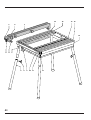
Description (fig. A1 - A3)
Your stable and rigid DE2000/DE2011 Combi-Table has been designed to
extend the versatility of your router or circular saw, enabling them to be
used in a stationary mode.
Fig. A1 - Combi-Table
1 No-volt release switch
2 Socket
3 Fine adjustment clamp
4 Fine adjuster
5 Locking screw (front)
6 Locking screw (back)
7 Star knob
8 Leg
9 Thumbscrew
10 Scale
11-14 Slide rail
15-16 Dovetail grooves
17 Push stick holder
Fig. A2 - DE2011 (option)
18 Saw mounting plate
19 Fixing screws
20 Parallel rip fence with profile (49)
21 Sliding mitre fence
22 Push stick
23 Cutting insert
24 Dust spout
25 Adjustable saw blade guard
26 Dust guard holder
Fig. A3 - DE2000
27 Router mounting plate
28 Fixing screws
29 Router fence with faces (40)
30 Transparent cutter guard
31 Cutter guard bracket
32 Cutting insert
33 Dust spout
We recommend the following saws for use with the DE2011 (option):
Elu MH85 DEWALT DW62 Metabo KsE 1668s-Signal
Elu MH151 D
EWALT DW65 Metabo Ks 1468 S
Elu MH165 D
EWALT DW86 Metabo Ks 1255 S
Elu MH265 Bosch GKS 65
Elu MH286 Bosch GKS 66 CE
We recommend the following Routers for use with the DE2000 Router
Table (all models: construction year from 1990):
Elu MOF96 DEWALT DW613
Elu OF97 DEWALT DW625E
Elu MOF131 DEWALT DW620
Elu MOF177 DEWALT DW621
With the optional mounting kit (DE2010), the DEWALT Router Table
DE2000 also accepts most of the common routers in the market and older
models.
Do not mount any Power Tools not specified in this list.
Mains plug replacement (U.K. & Ireland only)
• Should your mains plug need replacing and you are competent to do
this, proceed as instructed below. If you are in doubt, contact an
authorized DEWALT repair agent or a qualified electrician.
• Disconnect the plug from the supply.
• Cut off the plug and dispose of it safely; a plug with bared copper
conductors is dangerous if engaged in a live socket outlet.
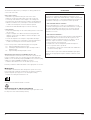
• Only fit 13 Amperes BS1363A approved plugs fitted with the correctly
rated fuse (1).
• The cable wire colours, or a letter, will be marked at the connection
points of most good quality plugs. Attach the wires to their respective
points in the plug (see below). Brown is for Live (L) (2) and Blue is for
Neutral (N) (4).
• Before replacing the top cover of the mains plug ensure that the cable
restraint (3) is holding the outer sheath of the cable firmly and that the
two leads are correctly fixed at the terminal screws.
Never use a light socket.
Never connect the live (L) or neutral (N) wires to the earth pin
marked E or .
For 115 V units with a power rating exceeding 1500 W, we recommend to
fit a plug to BS4343 standard.
Using an extension cable
If an extension cable is required, use an approved extension cable suitable
for the power input of this tool (see technical data). The minimum
conductor size is 1.5 mm
2
. When using a cable reel, always unwind the
cable completely.

ENGLISH
en - 3 20
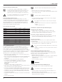
Also refer to the table below.
Conductor size (mm
2
) Cable rating (Amperes)
0.75 6
1.00 10
1.50 15
2.50 20
4.00 25
Cable length (m)
7.5 15 25 30 45 60
Voltage Amperes Cable rating (Amperes)
115 0 - 2.0 6 6 6 6 6 10
2.1 - 3.4 6 6 6 6 15 15
3.5 - 5.0 6 6 10 15 20 20
5.1 - 7.0 10 10 15 20 20 25
7.1 - 12.0 15 15 20 25 25 -
12.1 - 20.0 20 20 25 - - -
230 0 - 2.0 6 6 6 6 6 6
2.1 - 3.4 6 6 6 6 6 6
3.5 - 5.0 6 6 6 6 10 15
5.1 - 7.0 10 10 10 10 15 15
7.1 - 12.0 15 15 15 15 20 20
12.1 - 20.0 20 20 20 20 25 -
Assembly and adjustment
Prior to assembly and adjustment always unplug the
Combi-Table.
General
Mounting the legs (fig. A1)
The Combi-Table can be used with or without the legs (8).
When mounting a router without using the legs, check that there is
sufficient space to release the router carriage.
• Put the table on its side.
• Loosen the four wing nuts (9) and insert the legs. Turn the wing nuts to
the inside and tighten them.
• Turn the table over and adjust the legs to level the table. Tighten the
wing nuts securely.
• Secure the switch lock (Velcro) supplied with the Combi-Table to one
of the leg wing nuts using the strap.
Mounting the fences and accessories (fig. A1 - A3)
Your Combi-Table is provided with slide rails and dovetailed grooves
which accept the accessories.
• Slide the fences into the appropriate slide rails or grooves in the table top:
For the parallel rip fence (DE2011) or router fence (DE2000), use slide
rails (11) and (12).
For the mitre fence, use groove (16).
• DE2011 - Slide the saw blade guard (25) onto the saw table using the
slide rail (12) and tighten the dust guard holder (26).
• DE2000 - Slide the cutter guard bracket (31) into the groove in the rear
face of the router fence (29) and place the cutter guard (30) on top.
Each time you move the faces on the parallel fence, make sure
that the cutter guard is correctly positioned over the cutter.
Adjusting the parallel rip fence (20) or router fence (29) (fig. A1 - A3)
To allow optimum efficiency of the fine adjuster (4), the fine adjustment
clamp (3) must be centred in its slot.
• Slacken the fine adjustment clamp (3) and the locking screws (5) and (6).
• Slide the fence to the required position.
For accurate cuts:
• Lock the fine adjustment clamp (3).
• Use the fine adjuster (4) to position the fence accurately. Each
graduation of the knob corresponds to a change of 0.1 mm.
• First lock the front screw (5) and then the back screw (6).
• Check the distance from fence to saw or cutter.
• Never make any cuts without locking the screws (5 & 6).
• The best way to move the parallel fence is to do it one-handed
from the front.
DE2011 (option)
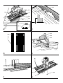
Mounting the circular saw (fig. A2 & B)
The fixing screws (19) are equipped with a locking lip.
Do not slacken the fixing screws more than two turns.
• Slacken the four fixing screws (19) in the saw mounting plate (18) and
remove the mounting plate.
• Place the mounting plate upside down on the table top.
• Slacken the nuts (35 & 37) and slide the mounting profile (36) away.
• Open the lower guard of your saw and insert the saw blade into the
slot (34).
• Position your saw as accurately as possible in the middle of the slot (34),
side to side and front to back.
• Lock the ON/OFF-switch of the saw using the Velcro switch lock.
For optimal securing of the circular saw, both horizontal and
vertival movements must be eliminated.
To eliminate horizontal movements
• Clamp the saw shoe using the mounting profile (36) and the four
brackets (38) and tighten all the nuts (35 & 37) finger-tight.
To eliminate vertical movement
The clamps (39) firmly press your saw onto the mounting plate.
The correct adjustment of the clamps is a matter of experience.
Proceed as follows:
• Loosen the nut (59) to release the spring tension of the clamp.
• To adjust the clamp height, use bolt (58).
• Lock the clamps using the nuts (59). Do not overtighten. At this stage,
the saw must simply not come off the mounting plate when turning it over.
• Keep the rear end of the clamps within the dotted line as shown.
• Turn the saw mounting plate (18) over leading the cord into the table.
Make sure the mounting plate is flush with the worktop and tighten the
four fixing screws (19).
Adjusting the circular saw (the saw blade) (fig. A2, B & C)
When using the same saw all the time in the Combi-Table, this adjustment
only needs to be done once.
For high precision cuts, always adjust the saw to the parallel
fence, never to the lines on the table top.
• Slide the parallel rip fence (20) to the outer edge of the slot (34) in the
cutting insert. Adjust the fence as described above.
• Measure the distance from the saw blade to the fence at both ends of
the saw blade (Refer to drawing C).
• The distance should be the same at both ends.

ENGLISH
21 en - 4
For DW365 and Elu MH165 only
To make mitre cuts with the DW365/MH165, the attached plastic support
is required. The maximum depth of cut is reduced to 47 mm.
Due to the construction of the DW365/MH165, you cannot release the
depth of cut of the saw down to zero, which is necessary to replace the
standard cutting insert (23) to the appropriate bevel cutting insert. With the
mounted plastic support you can change the inserts without any problem.
• Remove the mounting profile (36) and one of the clamps (39)
underneath the saw mounting plate.
• Slide two of the plastic supports into each of the grooves near the slot (34)
facing the high edges to the outside of the mounting plate.
• Mount the clamp (39) and the profile (36) back to the plate.
• To hold the DW365/MH165 properly, you need to turn the metal
brackets (38) to the other side. Unscrew the nuts (37) and turn the
brackets around.
Attention:
You must swap the left brackets with the right ones.
• Open the lower guard of the DW365/MH165 and insert the saw blade
into the slot (34) by placing the saw onto the plastic supports.
• To get the parallel adjustment of the saw blade to the slot (34), place
the edge under the saw base-plate against the edge of the support.
(additional adjustment of the saw is not required).
• Place the brackets (38) and the mounting profile (36) as
described in the instruction manual.
• Place and adjust the clamps (39) as described in the
instruction manual.
• Tighten all nuts securely.
• Set the depth of cut of your saw to 0 mm.
• Loosen the screw (44) and pull out the cutting insert (23).
• Slide the new cutting insert into the saw mounting plate and tighten the
screw (44).
Adjust the bevel angle of your saw.
• Move the saw blade up through the slot in the new cutting insert and
adjust the depth of cut.
• Never use the saw table without the appropriate cutting insert.
• Rotate the blade manually to check that the blade does not
scratch the cutting insert or the saw blade guard.
Mounting and adjusting the saw blade guard (fig. F)
Assembling the saw blade guard
• Mount the guard (25) to the bracket (45) using the wing nut (46). The
saw blade, the riving knife and the saw blade guard (25) must be in line.
• To adjust the guard, release the star knob (47).
Bevelling the saw blade guard
• To move the saw blade guard, loosen star knob (26A), and slide the
bracket (26) to the appropriate position.
Height adjustment
The height of the saw blade guard must be adjusted to the cutting depth.
• Loosen the wing nut (46), adjust the saw blade guard (25) using one of
the holes in the saw blade guard and tighten the wing nut (46).
• Check that the tip of the saw blade guard rests on the saw
table.
• Check that the guard can move up and down freely.
If not, adjust as follows:
• Slightly slacken the nuts (59) of the spring-loaded clamps and the
nuts (37) of the brackets (38).
• To adjust the blade, slightly move the saw.
• Check again.
• Tighten all nuts securely.
• Check that the blade is at right angles to the table surface
using a set square. (If adjustment is required, refer to the
instruction manual of the saw).
• For adjustment of the riving knife, also refer to the instruction
manual of your circular saw.
Rotate the blade manually to check that the blade does not
scratch the cutting insert or the saw blade guard.
The zero on the scale should coincide with the edge of the saw blade.
If required, adjust the scale.
• Loosen the two screws which hold the scale and adjust the scale in
the slots.
Removing your circular saw (fig. A2 & B)
• Slacken the four fixing screws (19) in the saw mounting plate (18) and
turn the mounting plate with circular saw upside down.
Do not slacken the fixing screws more than two turns.
• Slacken the clamps (39) only.
• Lift your circular saw away without changing the adjustment.
Depth of cut adjustment
For depth of cut adjustment, refer to the instruction manual of
your saw. Bear in mind that the maximum cutting depth is
reduced by approx. 10 mm when the circular saw is used as a
stationary tool.
For optimum results, allow the saw blade to protrude from the
workpiece by about 3 mm.
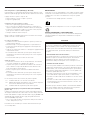
Bevel adjustment (fig. D)
To make bevel cuts with the Combi-Table, the cutting insert needs to be
replaced. Your DE2011 is supplied with 1 standard cutting insert and
4 bevel cutting inserts to suit various bevel angles. The inserts are marked
A, B, C and D. The table below shows which insert to use for your saw at
specific bevel angles.
Cutting insert, angles in degrees
ABCD
Elu MH151 12-23 24-39 41-45 -
Elu MH165 9-18 18-30 30-40 41-47
Elu MH265 8-15 18-24 26-33 38-45
Elu MH85 9-18 21-30 31-39 -
Elu MH286 7-13 18-29 27-35 40-45
D
E
WALT DW62 3-11 19-31 34-45 -
D
E
WALT DW65 8-15 18-24 26-33 38-45
D
E
WALT DW86 7-13 18-29 27-35 40-45
D
E
WALT DW351 12-23 24-39 41-45 -
D
E
WALT DW365 9-18 18-30 30-40 41-47
Bosch GKS 65 8-21 21-32 33-41 45
Bosch GKS 66 CE 8-21 21-32 33-41 45
Metabo KsE 1668s-Signal 19-36 38-45 - -
Metabo Ks 1468 S 19-36 38-45
Metabo Ks 1266 S 19-36 38-45

en - 5 22
ENGLISH
Reversible parallel rip fence profile (fig. E)
The profile (49) in the parallel rip fence (20) can be used in two positions.
To turn the face into the appropriate position, proceed as follows:
• Loosen the star knobs (7).
• Pull out the profile (49) and install it as required. The backing plates (50)
of the star knobs (7) engage in the slide rail (51).
• Tighten the star knobs (7).
DE2000
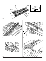
Mounting the DEWALT router (fig. G)
The fixing screws (28) are equipped with a locking lip.
Do not slacken the fixing screws more than two turns.
• Slacken the four fixing screws in the router mounting plate (27) and
remove the mounting plate.
• Place the router mounting plate (27) upside down on the table top.
• Place the router on the mounting plate (27) aligning the screw holes in
the router base with the holes in the mounting plate.
• Tighten the screws (53) securely.
For Elu MOF96, DEWALT DW613: use two of the longer screws;
for Elu OF97, DEWALT DW620 & DW621 use the two short screws;
for Elu MOF131, Elu MOF177 & DEWALT DW625E: 3 screws.
• Lock the router in ON position.
• Turn the router mounting plate over leading the cord into the table.
Make sure the mounting plate is flush with the table top and tighten the
four fixing screws (28).
Depth of cut adjustment
• Install an appropriate cutter.
• Depress the router to the required depth of cut.
For depth of cut adjustment, refer to the instruction manual of
your router.
• Always secure your router using the fine adjustment device. It is not
sufficient to use the carriage lock.
• Not all routers are equipped with a fine adjustment device. Consult
your dealer for further information.
Mounting the router and centring the cutter with DE2010 (fig. G & H)
When using the DE2000 in combination with a DEWALT Router, it is not
necessary to centre the cutter, as the fixing screws are used. When using
routers of a different brand, the optional mounting kit DE2010 is required.
The following routers can be used with the mounting device DE2010:
Elu routers (construction year before 1990)
BOSCH GOF900ACE FESTO OF900 HITACHI M8V
GOF1300ACE OF900E M12V
GOF1700ACE OF2000 MAKITA 3612B
OF2000E
METABO OF1028
OFE1229 Signal
OFE1812
• Place the router mounting plate (27) upside down on a table top.
• Place the router on the mounting plate with the spindle in the centre of
the cutter hole (52).
• Install the mounting kit DE2010 as shown in figure H.
To eliminate horizontal movements
• Clamp the router base using the mounting profiles (54) and centring
blocks (55) and tighten the nuts (56).
To eliminate vertical movement
The clamps (57) accurately secure your router in place. The correct
adjustment of the clamps is a matter of experience. Proceed as follows:
• To adjust the clamp height, use bolt (58).
• Lock the clamps using the nuts (59).
• Keep the rear end of the clamps within the dotted line as shown.
• Turn the router mounting plate (27) over leading the cord into the table
and tighten the four fixing screws (28).
Adjusting the router/cutter
When using the same router all the time in the Combi-Table, this adjustment
needs to be done only once.
• Mount an appropriate cutter and plunge the router to its maximum
cutting depth.
• Measure the distance between the shank/cutting edge and the edge of
the cutter hole (52) at various positions.
• The distance should be the same at all positions. If not, adjust as follows:
• Slightly slacken the nuts of the spring loaded clamps (57) and the nuts
of the profiles (54) and centring blocks (55).
• Adjust the router.
• Check again.
• Tighten all nuts securely.
Adjusting the router fence (fig. I)
The router fence (29) is equipped with two faces (40).
• Loosen the star knobs (7) on the router fence (29).
• Slide the two faces as close to the cutter as possible.
• Tighten the star knobs (7).
Each time you move the faces on the parallel fence, make sure
that the cutter guard is correctly positioned over the cutter.
Adjusting the cutter guard (fig. A3)
The cutter guard (30) hinges in the bracket (31) which in turn slides in the
face (40).
• Slide the cutter guard to the required position. Make sure it cannot be
caught by the cutter.
Changing the cutting inserts (fig. A3)
Your DE2000 Combi-Table is supplied with four different cutting inserts (32)
to suit different cutter diameters.
The standard diameters are: 12, 22, 32 and 42 mm.
Always use the cutting insert with a cutter hole one size larger than your
cutter.
Lower the cutter.
• Loosen the screw (44) and pull out the cutting insert (32).
• Slide the new cutting insert into the mounting plate and tighten the
screw (44).
Instructions for use
• Always observe the safety instructions and applicable
regulations.
• Whenever possible, use a push stick.

ENGLISH
23 en - 6
Prior to operation:
• Check that the Power Tool is mounted as described above.
• Check that all guards and fences are in perfect working order and that
they are mounted correctly.
• Connect a dust extraction set in compliance with the relevant
regulations on dust extraction levels.
Switching ON and OFF (fig. J)
• Lock the Power Tool in ON-position.
• Lift the cover (60) of the no-volt release switch (1) and plug in the
Power Tool.
• Connect the Combi-Table to the mains by plugging an extension cable
into the socket (2).
The ON/OFF-switch of your Combi-Table is a no-volt release
switch (1). Should the power be shut OFF for some reason,
the switch has to be deliberately reactivated.
• Press the green ON button (62) of the no-volt release switch (1) to start
the Power Tool.
• To switch OFF, press the red OFF button (61) of the no-volt release
switch (1). Always switch OFF the tool when work is finished and
before unplugging.
DE2011 (option)
Basic saw cuts
Vertical ripping (fig. A1 & A2)
• Set the blade of your circular saw to 0°.
• Set the blade height of your circular saw as described in the instruction
manual of your saw.
• Mount the parallel rip fence (20) onto the table, to the right of the blade.
• Depending on the height and width of the workpiece, use the fence
height that allows optimum access between fence and blade.
• Slide the parallel rip fence (20) across the blade and position it using
the scale (10) at the front of the table. The scrap or off-cut is guided to
the left of the blade. Use the fine adjustment for accurate cutting as
described in the section “Adjusting the parallel fence”.
• Switch the Combi-Table ON.
• Slowly feed the workpiece underneath the front of the guard, keeping it
firmly pressed against the rip fence. Allow the teeth to cut and do not
force the workpiece through the blade. The blade speed should be
kept constant.
• When ripping small workpieces (< 120 mm), always use the push
stick (22).
• When not in use, keep the push stick (22) in its holder (17).
• When the cut is completed, switch the Combi-Table OFF immediately.
Bevel ripping
• Set the blade to the required bevel angle as described in the section
“Bevel adjustment”.
Make sure that the appropriate cutting insert is used and that
the blade does not scratch the cutting insert.
• Set the saw blade guard in line to the new position of the saw blade.
• Bevel the saw blade guard. Refer to the section “Bevelling the saw
blade guard” and to fig. F.
• Make sure that the saw blade runs in the middle of the saw blade guard.
• Proceed as for vertical ripping.
Straight and mitre cross-cutting (fig. A2 & K)
• Remove the parallel rip fence (20).
• To mount the sliding mitre fence (21), insert the long end of the slider bar
(64) into the groove (16). For a straight or mitre cross-cut, loosen the
wing nut (65) and rotate the fence to set the angle required (0° - 45°).
• Tighten the wing nut (65) securely.
• Loosen the two fence locking screws (66) and slide the slanting edge (63)
of the fence towards the blade until it just clears the blade when the
assembly is slid to the rear.
• Tighten the fence locking screws.
• Pull the assembly to the front and place the wood to be cut against the
profile (21) of the fence.
• Switch the Combi-Table ON, hold the wood firmly and slide the
assembly along the groove to take the wood into the blade.
• When the cut is completed, switch the Combi-Table OFF immediately.
Bevel cross-cut
• Set the blade to the required bevel angle as described in the section
“Bevel adjustment”.
Make sure that the appropriate cutting insert is used and that
the blade does not scratch the cutting insert.
• Adjust the circular saw to the correct height.
• Set the mitre fence to 0°.
• Proceed as for straight and mitre cross-cutting.
Compound mitre
A compound mitre cut is a combination of a bevel cut and a mitre cut.
• Proceed as for bevel cross-cuts, setting the mitre fence to the required
mitre angle.
Cutting round workpieces
• When cutting round workpieces, use a device (not provided) to prevent
rotation of the workpiece on either side of the blade.
Do not use the DE2000 in combination with DE2011 for
cutting firewood.
DE2000
Direction of feed
• Always feed the material against the direction of rotation.
• Always feed from the front panel (switch end).
Edge trimming (rebating) and profile cutting (fig. A3 & I)
• Install the appropriate cutter and set the router to the appropriate
depth of cut using the fine height adjustment of the router.
• Check that the appropriate cutting insert (32) is mounted.
• Mount the router fence (29) onto the table and slide it to the middle of
the cutter.
• Loosen the star knobs (7), position the faces (40) as close to the bit as
possible and tighten the star knobs.
The side of the material which will be trimmed must be guided
along the router fence.
• Use the fine adjuster for positioning the router fence in relation to the
expected width of cut.
• Slide the cutter guard (30) to the correct position.
• Press the workpiece against the fence and the table top. When using
the optional down hold guards (DE2007 & DE2008), install them as
described in the section “Horizontal down hold guard (DE2007) and
vertical down hold guard (DE2008) (fig. M2)”.
• Switch the Combi-Table ON.

en - 7 24
ENGLISH
• Feed the material at an even speed and make the cut in one smooth pass.
The correct feed speed is a matter of experience: too low speed will
produce burn marks on the wood, whereas too high speed will
overload your router.
• When the cut is completed, switch the Combi-Table OFF immediately.
Cutting grooves (fig. L)
• Install the appropriate cutter.
• Check that the appropriate cutting insert is mounted.
• Mount the router fence (29) onto the table and slide it to the required
position.
• Slide the faces (40) towards each other to close the gap.
• Proceed as for edge trimming and profile cutting.
Optional accessories (fig. M1 - M4)
DE2011 (option)
Sliding table DE2001 (fig. M1)
The metal spacer bars, the two bolts and the two washers included in the
sliding table packaging are not needed for the Combi-Table.
This attachment fits to the left-hand side of the Combi-Table and allows
accurate cross-cutting of workpieces up to 720 mm wide.
There are two cast brackets (72) to support the table rail (73) and to
mount the sliding table to the Combi-Table. The top half of the dovetail is
cast into the brackets whereas the other half of the dovetail are two metal
wedges, held in place by Allen screws (74).
It is recommended to use the optional fence DE2002 together with the
sliding table.
Mounting the sliding table
• Loosen the two Allen screws (74), holding the wedges (75).
• Ensure that the table is locked tightly with the table locking knob (76).
• Slide the cast brackets (72) onto the slide rail (14 in fig. A1) and
position the front and rear brackets to allow the front edge of the front
bracket and the rear edge of the rear bracket to rest against the
sleeves. The front edge of the front bracket should now be in line with
the front edge of the table.
• Ensure that the two metal wedges (75) engage securely in the
underside of the dovetail.
• Tighten the Allen screws (74).
• With a straight edge, check that the extension table is flat and level
with the Combi-Table.
• If adjustment is required, loosen the Allen screw (77) in the centre of
the three screws located under the bracket (72). This screw secures
the rail to the bracket (refer to the inset in fig. M1).
• To raise or lower the table, screw in or out the two grub screws (78).
• To tilt the table, screw in or out these two grub screws as necessary.
• When the adjustment to the table is satisfactory, tighten the centre
Allen screw (77) in each bracket securely.
If the table is not absolutely parallel edge to edge to the Combi-Table, or if
the distance between the two needs altering, the table can be adjusted by
loosening the bolts (80) and moving the brackets (79) towards or away
from the rail. This adjustment is also required if any play develops between
the bearings (81) and the table rail.
Sawing with the sliding table
• When using the optional fence (DE2002), position it at the front of the
table ensuring that the end of the fence does not foul the blade.
• Hold the wood to be cut up against the fence.
• Ensure that the table locking knob (76) is loose.
• Switch ON and push the table slowly to the rear, thus passing the
wood through the blade.
DE2000
Conversion kit “Saw” DE2011
The conversion kit “Saw” converts your DE2000 Combi-Table into
a complete Saw table.
The conversion kit contains:
1 Saw mounting plate incl. mounting device
1 Parallel rip fence
1 Mitre fence
4 Cutting inserts (saw)
1 Saw blade guard with bracket
1 Push stick
1 Mounting device for DW365
1 Switch lock
For installation and applications, read the DE2011 sections in
this instruction manual.
Horizontal down hold guard (DE2007) and vertical down hold guard
(DE2008) (fig. M2)
The down hold guards (82 & 83) are very useful for professional routing.
A down hold guard ensures constant pressure to the workpiece against
the table top and the fence.
Assembling and mounting the vertical down hold guard
• Loosen the three Allen screws (84) on the down hold bracket (85).
• Slide the bracket onto the router fence (29 in fig. A3) up to the dust
spout (33 in fig. A3).
• Mount the down hold guard (82) onto the bracket (85).
• Tighten the three Allen screws (84) securely.
• The down hold bracket can be left on the router fence, also when using
the cutter guard.
• Loosen the screw (86) and remove the down hold guard.
Mounting the horizontal down hold guard
• Loosen the knobs (87).
• Slide the horizontal down hold guard (83) in the groove (15 in fig. A1).
• Position the horizontal down hold guard where the cutter contacts the
workpiece.
• Tighten the knobs (87).
Using the down hold guards
• Without turning the machine ON, feed the workpiece until it touches
the cutter.
• Press the positioned down hold guards onto the workpiece until the
internal spring presses the material against the table and the fence.
Copy follower (DE2009) (fig. M3 & M4)
The copy follower (88) allows the user to work without the router fence
(freehand routing).
The copy set contains:
1 Copy follower with guard and brushes
1 Thrust block (89)
Mounting the copy follower
• Remove the router fence.
• Slide the arm (90) of the copy follower (88) and the thrust block (89)
into the right-hand groove (15 in fig. A1).
• Put the ball bearing guide (91) in the correct position on top of the
cutter. Refer to fig. M4.
• Tighten all knobs securely.

ENGLISH
25 en - 8
The thrust block (89) ensures your workpiece is always guided to the
correct side of the cutter.
When edge moulding
• Mount the copy follower bearing off-centre to the cutter.
• Make the cut where the widest part of the cutter is exposed.
• Set the tip of the thrust block at a tangent to the cutting point.
• Ensure that the arm and the thrust block knobs are fully tightened.
• With the router OFF, move your workpiece in the desired manner,
to make sure that all points can be moulded as required.
• Switch the Combi-Table ON and proceed in the usual way.
Using templates
• Position the ball bearing over the cutter, making sure the centre of the
two are in line.
• Prepare a template. The difference between bearing and cutter
diameter corresponds to the difference between workpiece and
template dimensions.
• Secure the template to the workpiece using double-sided tape.
• With the router OFF, move your workpiece in the desired manner,
to make sure that all points can be moulded as required.
For the correct position of the ball bearing (91), refer to fig. M4:
• A Edge moulding with bearing off-centre.
• B Trimming facing material flush to edge of workpiece with a
trimming cutter.
• C Edge moulding following template contour.
Mounting the dust extraction set (DE2005) (fig. A2 - A3)
The dust extraction set has two hoses: one is to be connected to the
Power Tool and the other one to the dust spout on the Combi-Table
(DE2011: on the saw blade guard [25]; DE2000: on the router fence [29]).
A dust hose support (DE2006) is available as an option.
• Slide the dust extraction hose over the dust spout (24 or 33).
Consult your dealer for further information on the appropriate accessories.
Maintenance
Your DEWALT attachment has been designed to operate over a long
period of time with a minimum of maintenance. Continuous satisfactory
operation depends upon proper tool care and regular cleaning.
• Replace the cutting insert when worn out.
Cleaning
Regularly clean the attachment with a soft cloth.
Unwanted products and the environment
Take your attachment to an authorized DEWALT repair agent where it will
be disposed of in an environmentally safe way.
GUARANTEE
• 30 DAY NO RISK SATISFACTION GUARANTEE •
If you are not completely satisfied with the performance of your
DEWALT tool, simply return it within 30 days, complete as purchased,
to a participating Dealer, or an authorized DEWALT repair agent, for a
full refund or exchange. Proof of purchase must be produced.
• ONE YEAR FREE SERVICE CONTRACT •
If you need maintenance or service for your DEWALT tool, in the
12 months following purchase, it will be undertaken free of charge at
an authorized DEWALT repair agent. Proof of purchase must be
produced. Includes labour and spare parts for the attachments.
Excludes accessories.
• ONE YEAR FULL WARRANTY •
If your DEWALT product becomes defective due to faulty materials or
workmanship within 12 months from the date of purchase, we
guarantee to replace all defective parts free of charge or, at our
discretion, replace the unit free of charge provided that:
• The product has not been misused.
• Repairs have not been attempted by unauthorized persons.
• Proof of purchase date is produced.
This guarantee is offered as an extra benefit and is additional to
consumers statutory rights.
For the location of your nearest authorized DEWALT repair agent,
please use the appropriate telephone number on the back of this
manual.
Page is loading ...
Page is loading ...
Page is loading ...
Page is loading ...
Page is loading ...
Page is loading ...
Page is loading ...
Page is loading ...
Page is loading ...
Page is loading ...
Page is loading ...
Page is loading ...
Page is loading ...
Page is loading ...
Page is loading ...
Page is loading ...
Page is loading ...
Page is loading ...
Page is loading ...
Page is loading ...
Page is loading ...
Page is loading ...
Page is loading ...
Page is loading ...
Page is loading ...
Page is loading ...
Page is loading ...
Page is loading ...
Page is loading ...
Page is loading ...
Page is loading ...
Page is loading ...
Page is loading ...
Page is loading ...
Page is loading ...
Page is loading ...
Page is loading ...
Page is loading ...
Page is loading ...
Page is loading ...
Page is loading ...
Page is loading ...
Page is loading ...
Page is loading ...
Page is loading ...
Page is loading ...
Page is loading ...
Page is loading ...
Page is loading ...
Page is loading ...
Page is loading ...
Page is loading ...
Page is loading ...
Page is loading ...
Page is loading ...
Page is loading ...
Page is loading ...
Page is loading ...
Page is loading ...
Page is loading ...
Page is loading ...
Page is loading ...
Page is loading ...
Page is loading ...
Page is loading ...
Page is loading ...
Page is loading ...
Page is loading ...
Page is loading ...
Page is loading ...
Page is loading ...
Page is loading ...
Page is loading ...
Page is loading ...

Belgique et Luxembourg DEWALT Tel: 02
719
07
12
België en Luxemburg Weihoek 1, Nossegem Fax: 02
721
40
45
1930 Zaventem-Zuid Service fax: 02
719
08
10
Danmark D
EWALT Tlf: 70
20
15
10
Hejrevang 26 B Fax: 48
14
13
99
3450 Allerød
Deutschland D
EWALT Tel: 06
12
62
16
Richard-Klinger-Straße Fax: 061
26
21
24
40
65510 Idstein
EÏÏ¿˜ D
EWALT TËÏ: 019
24
28
70
§ÂˆÊ ™˘ÁÁÚÔ‡ 154 Fax: 019
24
28
69
176 71 K·ÏÏÈı¤· Service: 019
24
28
76-7
∞ı‹Ó·
España D
EWALT Tel: 977
29
71
00
Ctra de Acceso Fax: 977
29
71
38
a Roda de Barà, km 0,7 Fax: 977
29
71
19
43883 Roda de Barà, Tarragona
France D
EWALT Tel: 472
20
39
20
Le Paisy Tlx: 30
62
24F
BP 21 Fax: 472
20
39
00
69571 Dardilly Cedex
Helvetia D
EWALT/Rofo AG Tel: 037
43
40
60
Schweiz Warpel Fax: 037
43
40
61
3186 Düdingen
Ireland D
EWALT Tel: 012
78
18
00
Calpe House Rock Hill Fax: 012
78
18
11
Black Rock
Co. Dublin
Italia D
EWALT Tel: 03
92
38
72
04
Viale Elvezia 2 Fax: 03
92
38
75
93
20052 Monza (Mi)
Nederland D
EWALT Tel: 07
65
08
22
01
Florijnstraat 10 Fax: 07
65
03
81
84
4879 AH Etten-Leur
Norge D
EWALT Tel: 22
90
99
00
Strømsveien 344 Fax: 22
90
99
01
1081 Oslo
Österreich D
EWALT Tel: 022
26
61
16
Werkzeugevertriebs GmbH Tlx: 13228 Black A
Erlaaerstraße 165 Fax: 022
26
61
16
14
Postfach 320,1231 Wien
Portugal D
EWALT Tel: 468 7513/7613
Rua Egas Moniz 173 Tlx: 16607 Bladec P
Apartado 19, S. João do Estoril Fax: 466
38
41
2768 Estoril, Codex
Suomi D
EWALT Puh: 98 25
45
40
Rälssitie 7 C Fax: 98 25
45
444
01510 Vantaa
Frälsevägen 7 C Tel: 98 25
45
40
01510 Vanda Fax: 98 25
45
444
Sverige D
EWALT Tel: 031
68
61
00
Box 603 Fax: 031
68
60
08
421 26 Västra Frölunda
Besöksadr. Ekonomivägen 11
United Kingdom D
EWALT Tel: 017
53
57
42
77
210 Bath Road Fax: 017
53
52
13
12
Slough
Berks SL1 3YD
07-97
-
 1
1
-
 2
2
-
 3
3
-
 4
4
-
 5
5
-
 6
6
-
 7
7
-
 8
8
-
 9
9
-
 10
10
-
 11
11
-
 12
12
-
 13
13
-
 14
14
-
 15
15
-
 16
16
-
 17
17
-
 18
18
-
 19
19
-
 20
20
-
 21
21
-
 22
22
-
 23
23
-
 24
24
-
 25
25
-
 26
26
-
 27
27
-
 28
28
-
 29
29
-
 30
30
-
 31
31
-
 32
32
-
 33
33
-
 34
34
-
 35
35
-
 36
36
-
 37
37
-
 38
38
-
 39
39
-
 40
40
-
 41
41
-
 42
42
-
 43
43
-
 44
44
-
 45
45
-
 46
46
-
 47
47
-
 48
48
-
 49
49
-
 50
50
-
 51
51
-
 52
52
-
 53
53
-
 54
54
-
 55
55
-
 56
56
-
 57
57
-
 58
58
-
 59
59
-
 60
60
-
 61
61
-
 62
62
-
 63
63
-
 64
64
-
 65
65
-
 66
66
-
 67
67
-
 68
68
-
 69
69
-
 70
70
-
 71
71
-
 72
72
-
 73
73
-
 74
74
-
 75
75
-
 76
76
-
 77
77
-
 78
78
-
 79
79
-
 80
80
-
 81
81
-
 82
82
-
 83
83
-
 84
84
-
 85
85
-
 86
86
-
 87
87
-
 88
88
-
 89
89
-
 90
90
-
 91
91
-
 92
92
-
 93
93
-
 94
94
-
 95
95
-
 96
96
-
 97
97
-
 98
98
-
 99
99
-
 100
100
-
 101
101
-
 102
102
-
 103
103
-
 104
104
-
 105
105
-
 106
106
-
 107
107
-
 108
108


Ask a question and I''ll find the answer in the document
Finding information in a document is now easier with AI
in other languages
- italiano: DeWalt DE2000 Manuale utente
- français: DeWalt DE2000 Manuel utilisateur
- español: DeWalt DE2000 Manual de usuario
- Deutsch: DeWalt DE2000 Benutzerhandbuch
- Nederlands: DeWalt DE2000 Handleiding
- português: DeWalt DE2000 Manual do usuário
- dansk: DeWalt DE2000 Brugermanual
- svenska: DeWalt DE2000 Användarmanual
- suomi: DeWalt DE2000 Ohjekirja