Philips 20PT9007D/17 User manual
- Category
- Network antennas
- Type
- User manual
This manual is also suitable for

Better
Component Video
Input (CVI)
Provides superior picture quality
by separating the green, blue and
red luminance signals. Typically
used with red/white audio cables.
Basic
Composite Audio/Video
Separate video (yellow) and
audio (red/white) cables that
provide a basic connection from
the set-top box and other devices.
Note: The color of audio inputs
may differ, e.g. Red/white or
red/back.
RF
0
Provides a basic
connection
for antenna or cable.
Provides both audio
and video.
Basic
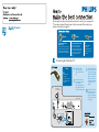
Use this guide to achieve the optimal connection for each of your components.
TV can support these different types of cable connection. Please check your
device to see which one applies.
Connecting Set-Top Box to TV
Connect RF cable
from wall to input at
the back of the set-top
box.
Set the out channel of
the set-top box to CH 3
or 4 if available.
Press the Ana/Dig button
on the remote control to
set the TV to analog mode.
Basic
Provides a basic
connection
for antenna or cable.
Provides both audio
and video.
Use second RF cable to
connect the set-top box
to the TV input (75 ).
Note: This connection
gives mono sound. For
stereo sound use also
composite audio/video
connection (refer to
panel 2).
Cable Signal IN
from Cable Company
Back of Set-top Box
75 Input
TV
Set the TV to the same
channel as the set-top
box output channel.
Change the channels at
the set-top box to view
the program.

Connecting Input Device to TV (eg. DVD player, Digital Recorder, VCR, Video Camera, Games Console)
Better
Component Video
Input (CVI)
Provides superior picture quality
by separating the green, blue and
red luminance signals. Typically
used with red/white audio cables.
Composite Audio/Video
Basic
Composite Audio/Video
Separate video (yellow) and
audio (red/white) cables that
provide a basic connection from
the set-top box and other devices.
Note: The color of audio inputs
may differ, e.g. Red/white or
red/back.
A
Connect the video
cable (yellow) to the
VIDEO AV input on
back of TV and the
corresponding video
output on back
of VCR.
C
Turn on the TV and
VCR. Press the
SOURCE button on
the remote control
until AV1 appears on
TV screen.
Connect audio cables
(red/white) to audio
AV inputs on back of
TV and the
corresponding audio
outputs (L & R) on
back of VCR.
Insert pre-recorded
videotape into VCR
and press PLAY to
verify correct
connection.
B
D
OR
CompositeAudio/Video
TV Front Jack Panel
Basic
Composite Audio/Video
Separate video (yellow) and
audio (red/white) cables that
provide a basic connection from
the set-top box and other devices.
Note: The color of audio inputs
may differ, e.g. Red/white or
red/back.
OR
2
Component Video Input
Note: for mono devices, connect only white audio cable from
the device s audio output to white audio input on the front of TV.
A
Connect the video
cable (yellow) from the
video output on camera
(or other device)to the
video input (yellow)
located on the front of TV.
C
Turn on TV and the
device. Press the
SOURCE button on
the remote control
until FRONT appears on
TV screen.
Connect audio cables
(red/white) from audio
outputs on device to audio
inputs (red/white) on the
front of TV.
Press PLAY on the
device to verify correct
connection.
B
D
,
A
Insert Component
Video connectors into
their corresponding
jacks on both DVD
player/DVD recorder
and TV (sometimes
labeled Y, Pb and Pr).
Connect red/white
audio cables to the
audio output jacks
on DVD player/DVD
recorder and audio
AV inputs on TV.
B
C
Turn on TV and DVD
player/DVD recorder.
Press the SOURCE
button on the remote
control until CVI
appears on TV screen.
Insert a pre-recorded
DVD into DVD player/
DVD recorder and
press PLAY to verify
correct connection.
D
Note: CVI and AV1 share the same audio channels and can t
be used at the same time. If you connect them simultaneously,
you can only hear sound coming from CVI signal.
,
Video Camera
TV
Video Camera Jack Panel
TV Jack Panel
A
B
S-VIDEOVIDEO AUDIO OUT
RL
C
SOURCE ButtonRemote
Control
SOURCE Button
Back of DVD player / Recorder
TV
Pr
TV Jack Panel
Remote
Control
C
B
A
TV
Back of VCR
TV Jack Panel
S-VIDEO
OUT
VIDEO
OUT
AUDIO OUT
R L
ANT/CABLE
OUT
C
SOURCE ButtonRemote
Control
S-VIDEO
OUT
VIDEO
OUT
AUDIO
OUT
COMPONENT VIDEO
Y Pb
A
B
-
 1
1
-
 2
2


Philips 20PT9007D/17 User manual
- Category
- Network antennas
- Type
- User manual
- This manual is also suitable for
Ask a question and I''ll find the answer in the document
Finding information in a document is now easier with AI
Related papers
-
Philips 3139 125 User manual
-
-
-
-
-
-
-
-
-
Other documents
-
Magnavox 20MT4405 User manual
-
-
-
-
-
-
Technicolor - Thomson 51PW9303 User manual
-
Polycom 55PP9753 User manual
-
-