Omega OS531, OS532, OS53x-CF, OS533, OS534, OS530L, OS530HR OS523, OS524 Series User manual
- Category
- Digital body thermometers
- Type
- User manual

OS531, OS532, OS53x-CF,
OS533, OS534, OS530L, OS530HR
OS523, OS524 OMEGASCOPE
®
Handheld Infrared Thermometer
Shown with
Built-in Laser Sighting
TM
omega.com
e-mail: [email protected]
For latest product manuals:
omegamanual.info
User’s Guide
Shop online at
MADE IN

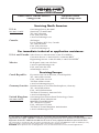
Servicing North America:
U.S.A.: One Omega Drive, Box 4047
ISO 9001 Certified Stamford, CT 06907-0047
Tel: (203) 359-1660
FAX: (203) 359-7700
e-mail: [email protected]
Canada: 976 Bergar
Laval (Quebec) H7L 5A1, Canada
Tel: (514) 856-6928
FAX: (514) 856-6886
e-mail: [email protected]
For immediate technical or application assistance:
U.S.A. and Canada: Sales Service: 1-800-826-6342/1-800-TC-OMEGA
®
Customer Service: 1-800-622-2378/1-800-622-BEST
®
Engineering Service: 1-800-872-9436/1-800-USA-WHEN
®
Mexico: En Espan˜ol: (001) 203-359-7803
e-mail: [email protected]
FAX: (001) 203-359-7807
Servicing Europe:
Czech Republic: Frystatska 184, 733 01 Karvina´, Czech Republic
Tel: +420 (0)59 6311899
FAX: +420 (0)59 6311114
Toll Free: 0800-1-66342
e-mail: [email protected]
Germany/Austria: Daimlerstrasse 26, D-75392 Deckenpfronn, Germany
Tel: +49 (0)7056 9398-0
FAX: +49 (0)7056 9398-29
Toll Free in Germany: 0800 639 7678
e-mail: [email protected]
United Kingdom: One Omega Drive, River Bend Technology Centre
ISO 9002 Certified Northbank, Irlam, Manchester
M44 5BD United Kingdom
Tel: +44 (0)161 777 6611
FAX: +44 (0)161 777 6622
Toll Free in United Kingdom: 0800-488-488
e-mail: [email protected]
OMEGAnet
®
Online Service Internet e-mail
omega.com [email protected]
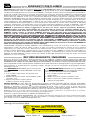
It is the policy of OMEGA Engineering, Inc. to comply with all worldwide safety and EMC/EMI
regulations that apply. OMEGA is constantly pursuing certification of its products to the European New
Approach Directives. OMEGA will add the CE mark to every appropriate device upon certification.
The information contained in this document is believed to be correct, but OMEGA accepts no liability for any
errors it contains, and reserves the right to alter specifications without notice.
WARNING: These products are not designed for use in, and should not be used for, human applications.

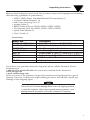
Unpacking Instructions
n4
Notes

i
Unpacking Instructions
NOTE
Remove the Packing List and verify that you have received all equipment, including
the following (quantities in parentheses):
• OS530/OS520 Series Handheld Infrared Thermometer (1)
• AA Size Lithium Batteries (4)
• Soft Cover Carrying Case (1)
• Analog Cable (1)
• RS232 Cable (only for OS533, OS534, OS523, OS524)
• CD Software (only for OS533, OS534, OS523, OS524)
• Quick Start Manual (1)
• User’s Guide (1)
Accessories
If you have any questions about the shipment, please call the Customer Service
Department at:
1-800-622-2378 or 203-359-1660. We can also be reached on the Internet at
www.omega.com
e-mail: [email protected]
When you receive the shipment, inspect the container and equipment for signs of
damage. Note any evidence of rough handling in transit. Immediately report any
damage to the shipping agent.
The carrier will not honor damage claims unless all shipping material
is saved for inspection. After examining and removing contents, save
packing material and carton in the event reshipment is necessary.
Model No. Description
OS520-ADAPTER-110V 110 VAC wall Adaptor, 9 VDC @ 200 mA
OS520-ADAPTER-220V 230 VAC wall Adaptor, 9 VDC @ 300 mA
OS520-RCC Hard Carrying Case, Standard
OS520-SC-RCC Hard Carrying Case, Large
88013K Surface Probe, K Type T/C, up to 815°C (1500°F)
88001K Surface Probe, K Type T/C, up to 482°C (900°F)
CAL-3-IR NIST Traceable Calibration
SC-520 Sighting Scope

ii

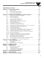
TABLE OF
CONTENTS
Page
Unpacking Instructions i
Chapter 1 General Description . . . . . . . . . . . . . . . . . . . . . . . . . . 1-1
1.1 Introduction 1-1
1.2 Parts of the Thermometer 1-4
1.2.1 Front of the Thermometer 1-4
1.2.2 Rear of the Thermometer 1-6
Chapter 2 Using the Handheld Infrared Thermometer . . . . . . . . . 2-1
2.1 How to Power the Thermometer 2-1
2.1.1 Battery Operation 2-1
2.1.2 ac Power Operation 2-1
2.2 Operating the Thermometer 2-2
2.2.1 Measurement Techniques 2-6
2.3 Real Time Mode (Active Operation) 2-8
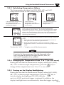
2.3.1 Adjusting Emissivity 2-11
2.3.2 Using the LOCK Function 2-11
2.3.3 Calculating Temperature Values 2-12
2.3.4 Changing the Temperature from °F to °C (or vice versa) 2-12
2.3.5 Turning on the Display Backlighting 2-12
2.3.6 Thermocouple Input 2-13
2.3.7 Using the Alarm Functions 2-14
2.3.8 Using Ambient Target Temperature Compensation 2-16
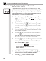
2.3.9 Sending Temperature Data to a Series Printer 2.17
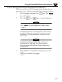
2.3.10 Sending Temperature Data to a Personal Computer 2.19
2.3.10.1 Software Installation 2.19
2.3.11 Storing the Temperature Data on Command 2-23
2.3.12 Erasing the Temperature Data form Memory 2.24
2.4 Recall Mode (Passive Operation) 2-25
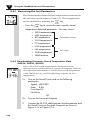
2.4.1 Reviewing the Last Parameters 2-27
2.4.2 Downloading PReviously Stored Temperature Data 2-27
2.4.3 Reviewing Previously Stored Temperature 2-29
Chapter 3 Laser Sighting . . . . . . . . . . . . . . . . . . . . . . . . . . . . . . . 3-1
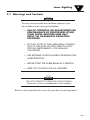
3.1 Warnings and Cautions 3-1
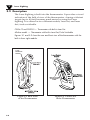
3.2 Description 3-2
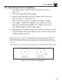
3.3 Operating the Laser Sighting 3-3
Chapter 4 Sighting Scope . . . . . . . . . . . . . . . . . . . . . . . . . . . . . . 4-1
Chapter 5 Maintenance . . . . . . . . . . . . . . . . . . . . . . . . . . . . . . . 5-1
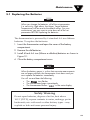
5.1 Replacing the Batteries 5-1
5.2 Cleaning the Lens 5-2
5.3 Calibrating the Thermometer 5-2
5.4 Servicing the Laser Sighting 5-2
Chapter 6 Troubleshooting Guide . . . . . . . . . . . . . . . . . . . . . . . . 6-1
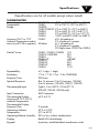
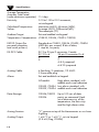
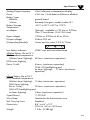
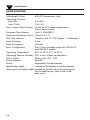
Chapter 7 Specifications . . . . . . . . . . . . . . . . . . . . . . . . . . . . . . . 7-1
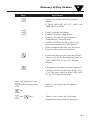
Chapter 8 Glossary of Key Strokes . . . . . . . . . . . . . . . . . . . . . . . 8-1
OS530/OS520 Series
Handheld Infrared Thermometer
iii
TABLE OF
CONTENTS

iv
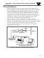
Appendix A How Infrared Thermometry Works . . . . . . . . . . . . . A-1
Appendix B Emissivity Values . . . . . . . . . . . . . . . . . . . . . . . . . . . B-1
Appendix C Determining an Unknown Emissivity . . . . . . . . . . . . C-1
Index . . . . . . . . . . . . . . . . . . . . . . . . . . . . . . . . . . . . . . . . . . . . . I-1
TABLE OF
CONTENTS

1-1
General Description
1
1.1 Introduction
The OS530/OS520 series Handheld Infrared (IR) Thermometers
provide non-contact temperature measurements up to 4500°F. They
offer effective solutions for many non-contact temperature
applications, including the following:
• Predictive Maintenance: Tracking temperature shifts
which indicate pending failure in solenoid valves.
• Energy Auditing: Locating wall insulation voids to reduce
building heating costs.
• Food Processing: Taking accurate temperature readings
without direct contact with the food or packaging material.
The IR thermometer provides information at a glance — the custom
backlit dual digital LCD displays both current and minimum,
maximum, average or differential temperatures. This versatile
instrument provides:
• Measurable target distances from 5 inches to approximately
100 feet
• Emissivity adjustable from 0.1 to 1.00 in 0.01 steps provides
ease of use when measuring a variety of surfaces.
• Built-in Laser sighting in Circle & Dot configurations.
• Thermocouple input available.
• An electronic trigger lock feature set via the keypad allows
continuous temperature measurement up to 4 times per
second.
• Audible and visual alarms. The high and low alarm points
are set via the keypad.
• 1 mV per degree (°F or °C) analog output, which allows
interfacing with data acquisition equipment (including
chart recorders, dataloggers and computers). OS524
provides 0.5 mV/Deg.
• Last temperature recall.
• Backlit display useful in low ambient light conditions.
• Powers from 4 AA size batteries or an ac adapter.
• RS232 serial communication to a PC or printer. This allows
downloading data for further analysis.
• Ambient target temperature compensation. This provides
more accuracy for measuring low emissivity targets.
• Record up to 100 temperature data points. Review the
recorded data on the thermometer LCD, as well as
downloading the data to a PC.

General Description
1
1-2
The thermometer is easy to use:
• Units have standard “V” groove aiming sights.
• Integral tripod mount permits hands-free operation, if
necessary.
• Temperature readings are switchable from °F to °C via the
keypad.
• Parameters, such as target material emissivity and alarm
setpoints, can be set and remain in memory until reset.
This instrument has a rugged and functional design, including:
• Sealed keypad display.
• Convenient trigger operation.
• Soft carrying case and wrist strap, for safety and ease of
carrying.
• Rubber boot around the lens and the display.
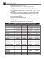
Table 1-1. OS530 Series Handheld Infrared Thermometer Features
Features
OS531 OS532 OS533 OS534
Accuracy* ±2% rdg ±1% rdg ±1% rdg ±1% rdg
Range 0 to 750°F 0 to 1000°F 0 to 1000°F 0 to 1600°F
(-18 to 400°C) (-18 to 538°C) (-18 to 538°C) (-18 to 871°C)
Emissivity adjustable adjustable adjustable adjustable
Backlit Dual Display standard standard standard standard
Distance to Spot
Size Ratio 10:1 10:1 20:1 30:1
Differential Temperature standard standard standard standard
Min/Max Temperature standard standard standard standard
Average Temperature standard standard standard standard
High Alarm standard standard standard standard
Thermocouple Input — standard standard standard
Audible Alarm
& Indicator standard standard standard standard
Analog Output 1mV/deg 1mV/deg 1mV/deg 1mV/deg
Built-in Laser Sighting dot/circle dot/circle dot/circle dot/circle
Trigger Lock standard standard standard standard
Last Temperature Recall standard standard standard standard
Low Alarm — — standard standard
Ambient Target
Temperature — — standard standard
Compensation
RS232 Interface — — standard standard
Data Storage — — — standard

1-3
General Description
1
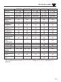
Features
OS530L OS530HR OS530L-CF OS533-CF OS534-CF
Accuracy* ±1% rdg 3°F (1.7 °C) ±1% rdg ±1% rdg ±1% rdg
Range -18 to 538°C -30 to 121°C -18 to 538°C -18 to 538°C -18 to 871°C
0 to 1000°F -22 to 250°F 0 to 1000°F 0 to 1000°F 0 to 1600°F
Emissivity Adjustable Adjustable Adjustable Adjustable Adjustable
Display Resolution 1°F or 1°C 0.1°For 0.1°C 1°F or 1°C 1°F or 1°C 1°F or 1°C
Backlit Dual std std std std std
Display
Field of view 10:1 20:1 .15"@6" .15"@6" .15"@6"
Differential
Temperature std std std std std
Min/Max
Temperature std std std std std
Average
Temperature std std std std std
High Alarm std std std std std
Low Alarm --- --- --- std std
Audible Buzzer
& Indicator
std std std std std
Ambient Target
Temp --- --- --- std std
Compensation
Analog Output 1 mV/Deg 1 mV/Deg 1 mV/Deg 1 mV/Deg 1 mV/Deg
RS232 Output --- --- --- std std
Data Storage --- --- --- --- std
Built-in Laser Dot/Circle Dot/Circle Dot Dot Dot
sighting
Trigger Lock std std std std std
Last Temperature
Recall std std std std std
Thermocouple
Input --- --- --- std std
* The temperature accuracy is 1% or 2% of Rdg or 3ºF (2ºC) whichever is
greater.

General Description
1
1-4
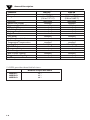
Distance to Spot Size Ratio
OS523-1 30:1
OS523-2 60:1
OS523-3 68:1
** OS523 provides three field of views:
Features OS523
**
OS524
Accuracy ±1%rdg ±1% rdg
Range 0 to 2500°F 1000 to 4500°F
(-18 to 1371°C) (538 to 2482°C)
Emissivity adjustable adjustable
Backlit Dual Display standard standard
Distance to Spot Size Ratio varies** 110:1
Differential Temperature standard standard
Min/Max Temperature standard standard
Average Temperature standard standard
High Alarm standard standard
Low Alarm standard standard
Audible Alarm & Indicator standard standard
Ambient Target
standard standard
Temperature Compensation
Analog Output 1 mV/deg 0.5 mV/deg
RS-232 Output standard standard
Thermocouple Input ––– –––
Data Storage standard standard
Built-in Laser Sighting standard standard
Trigger Lock standard standard
Last Temperature Recall standard standard

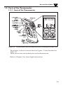
1.2 Parts of the Thermometer
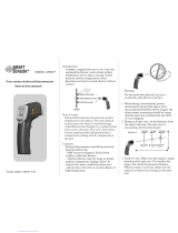
1.2.1 Front of the Thermometer
Figure 1-1. OS530/OS520 Series Handheld Infrared Thermometer Front View
The display is shown in more detail in Figure 1-2 and described in
Table 1-2.
There are no user-serviceable parts in the thermometer.
Refer to Chapter 3 for Laser Sight information.
°F
1-5
General Description
1

General Description
1
1-6
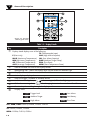
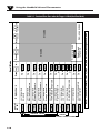
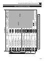
Figure 1-2. Display
and Keypad View
Table 1-2. Display Details
Key Description
➀
Display Mode displays one of the following:
TC (Thermocouple Input)
E (Emissivity) HAL (High Alarm Setpoint)
MAX (Maximum Temperature) LAL (Low Alarm Setpoint)
MIN (Minimum Temperature) AMB (Ambient Target Temp)
dIF (Differential Temperature) PRN (Print Data)
AVG (Average Temperature) MEM (Store Temperature Data)
➁
Data associated with one of the Display Modes
➂
Backlighting Icon - allows the display to be viewed under low ambient light
➃
Displays the units of measure in either °F or °C
➄
Main display - displays the current temperature
➅
Locks the trigger / Enables or Disables alarms
➆
▲ for incrementing data; is for turning on/off the backlighting
➇
▼ for decrementing data; is for changing the units of measure from °F to °C or vice versa
➈
Function key for scrolling through the display modes
➉
Display Icons
Trigger Lock Low Alarm
Ambient Target Low Battery
High Alarm Print Data
LAL, AMB, PRN: OS533, OS534, OS523, OS524
TC: OS532, OS533, OS534
MEM: OS534, OS523, OS524
LCK
HAL
LOBAT
ATC
LAL
PRN
°F °C
1
10
9
8
7
6
5
4
3
2

1-7
General Description
1
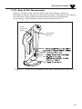
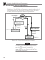
1.2.2 Rear of the Thermometer
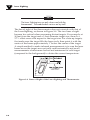
Figure 1-3 shows the various jacks that are used to connect a
recorder or the ac adapter to the thermometer. The figure also shows
the location of the tripod thread mount used for fixed point
monitoring. More details are provided in Section 2.2.1.
Figure 1-3. OS530 Series Handheld Infrared Thermometer Rear View
Laser Beam
Aperture
Laser
Dot/Circle
Switch

General Description
1
1-8
Notes

2-1
Using the Handheld Infrared Thermometer
2
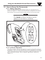
2.1 How to Power the Thermometer
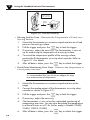
2.1.1 Battery Operation
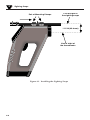
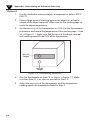
Invert the thermometer and install 4 fresh AA size batteries as
shown in Figure 2-1. Make sure the batteries’ polarities are correct,
the batteries are not put in backwards, and are of the same type.
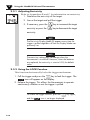
If the icon flashes, the batteries must be
replaced with fresh batteries immediately.
Figure 2-1. Installing the Batteries
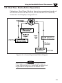
2.1.2 ac Power Operation
The thermometer may be operated on ac power using the optional
ac adapter. 120Vac/60 Hz and 220Vac/50 Hz adapters are available.
When operating on ac power the batteries supply backup power in
case of ac power failure. The ac adapter input jack is shown in
Figure 1-3.
NOTE

Using the Handheld Infrared Thermometer
2
2-2
2.2 Operating the Thermometer
1a. (Without the Laser Sighting) -Aim the thermometer at
the target to be measured. Use the “V” groove (shown in
Figure 1-1) on top of the thermometer to align the target to
the thermometer’s field of view. Look down the “V” groove
with one eye only, in order to guarantee proper sighting.
Pull and hold the trigger.
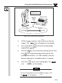
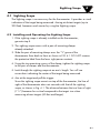
1b. (With the Laser Sighting) - Set the laser power switch to
the ON position. Aim at the target and pull the trigger.
The laser beam and the red power indicator LED will turn
on while the trigger is pulled. Refer to Chapter 3 for more
details on the Laser Sighting.
Figure 2-2. OS530/OS520 Series with Built-in Laser Sighting
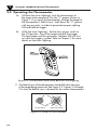
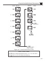
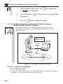
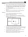
2. The field of view of the thermometer should fall within the area
of the target being measured. See Figure 2-3. Figures 2-4 through
2-6 show the field of view vs distance for the various thermometers.
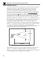
Figure 2-3. Field of View Positions
Field of View
Target
(ACCEPTABLE)
(UNACCEPTABLE)

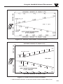
Figure 2-4. Field of View OS531, OS532, OS530L
Figure 2-5 Field of View OS533, OS530HR
2-3
Using the Handheld Infrared Thermometer
2
SPOT DIA. * (IN)
SPOT DIA. * (CM)
** Measurement distance is from the outside surface of the rubber boot.
4.8"
1.0" @ 0" to 20"
2.5cm @ 51cm
1.2"
1.0"
2.5
6.0
4.0
8.0
10.0
12.2
1601208040
1.0"
1.8"
2.4"
3.0"
3.6"
4.2"
1' 2'
200
8'6'
0**
DISTANCE: SENSOR TO OBJECT (FT)
DISTANCE: SENSOR TO OBJECT (CM)
SPOT DIA.* (IN)SPOT DIA.* (CM)
*SPOT DIAMETER MEASURED
AT 90% ENERGY
D:S = 20:1
4'
244
3' 5' 7'
20"

Using the Handheld Infrared Thermometer
2
2-4
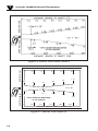
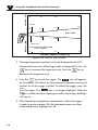
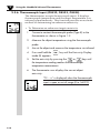
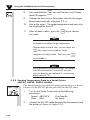
Figure 2-6 Field of View OS534, OS523-1
Figure 2-7 Field of View OS53x-CF
.45"
11.5
3"
SPOT DIA.* (MM)
*SPOT DIAMETER MEASURED
AT 90% ENERGY
7.6
SPOT DIA.* (IN)
DISTANCE: SENSOR LENS TO OBJECT (in.)
DISTANCE: SENSOR LENS TO OBJECT (cm.)
15.2
6"
9" 12"
15"
.15"
.39"
.78"
1.17"
3.9
9.9
19.9
29.9
D:S = 40:1
22.9
30.5
38.1
0.9"
22
0
0

2-5
Using the Handheld Infrared Thermometer
2
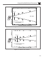
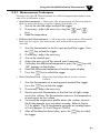
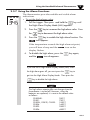
Figure 2-8 Field of View OS523-2
Figure 2-9 Field of View OS523-3
2.9"
0.9"@ 0
1.9"
22mm @ 0
1.2"
1.0"
31
26
48
75
0.9"
0'
3'
16'10'
*SPOT DIAMETER MEASURED
AT 90% ENERGY
D:S
=
60:1
5'
5.0
0
1.0 3.01.5
SPOT DIA.* (MM)
SPOT DIA.* (IN)
DISTANCE: SENSOR TO OBJECT (FT)
DISTANCE: SENSOR TO OBJECT (M)
7.0"
.35"@ 24"
1.6"
9mm @ 610mm
.8"
21
42
181
.9"
22
4.0"
101
0’
3’
16’10’2’ 5’
SPOT DIA.* (MM)
*SPOT DIAMETER MEASURED
AT 90% ENERGY
5.0
0
.61
1.5
1.0
3.0
SPOT DIA.* (IN)
DISTANCE: SENSOR TO OBJECT (FT)
DISTANCE: SENSOR TO OBJECT (M)
Page is loading ...
Page is loading ...
Page is loading ...
Page is loading ...
Page is loading ...
Page is loading ...
Page is loading ...
Page is loading ...
Page is loading ...
Page is loading ...
Page is loading ...
Page is loading ...
Page is loading ...
Page is loading ...
Page is loading ...
Page is loading ...
Page is loading ...
Page is loading ...
Page is loading ...
Page is loading ...
Page is loading ...
Page is loading ...
Page is loading ...
Page is loading ...
Page is loading ...
Page is loading ...
Page is loading ...
Page is loading ...
Page is loading ...
Page is loading ...
Page is loading ...
Page is loading ...
Page is loading ...
Page is loading ...
Page is loading ...
Page is loading ...
Page is loading ...
Page is loading ...
Page is loading ...
Page is loading ...
Page is loading ...
Page is loading ...
Page is loading ...
Page is loading ...
Page is loading ...
Page is loading ...
Page is loading ...
Page is loading ...
Page is loading ...
Page is loading ...
Page is loading ...
Page is loading ...
Page is loading ...
Page is loading ...
Page is loading ...
Page is loading ...
Page is loading ...
Page is loading ...
-
 1
1
-
 2
2
-
 3
3
-
 4
4
-
 5
5
-
 6
6
-
 7
7
-
 8
8
-
 9
9
-
 10
10
-
 11
11
-
 12
12
-
 13
13
-
 14
14
-
 15
15
-
 16
16
-
 17
17
-
 18
18
-
 19
19
-
 20
20
-
 21
21
-
 22
22
-
 23
23
-
 24
24
-
 25
25
-
 26
26
-
 27
27
-
 28
28
-
 29
29
-
 30
30
-
 31
31
-
 32
32
-
 33
33
-
 34
34
-
 35
35
-
 36
36
-
 37
37
-
 38
38
-
 39
39
-
 40
40
-
 41
41
-
 42
42
-
 43
43
-
 44
44
-
 45
45
-
 46
46
-
 47
47
-
 48
48
-
 49
49
-
 50
50
-
 51
51
-
 52
52
-
 53
53
-
 54
54
-
 55
55
-
 56
56
-
 57
57
-
 58
58
-
 59
59
-
 60
60
-
 61
61
-
 62
62
-
 63
63
-
 64
64
-
 65
65
-
 66
66
-
 67
67
-
 68
68
-
 69
69
-
 70
70
-
 71
71
-
 72
72
-
 73
73
-
 74
74
-
 75
75
-
 76
76
-
 77
77
-
 78
78


Omega OS531, OS532, OS53x-CF, OS533, OS534, OS530L, OS530HR OS523, OS524 Series User manual
- Category
- Digital body thermometers
- Type
- User manual
Ask a question and I''ll find the answer in the document
Finding information in a document is now easier with AI
Related papers
-
Omega OS530 Series User manual
-
-
-
Omega Engineering OSXL650 and OSXL653 User manual
-
-
-
-
-
-
Omega SP-001, SP-002 Owner's manual
Other documents
-
 LIFX L3BEAMKITUS Installation guide
-
 Smart Sensor AR330+ User manual
-
Aktakom ATE-2509 User manual
-
Omega Speaker Systems OS532 User manual
-
 AMPD ST350 Operating instructions
-
 WINTACT WT320 User manual
-
 Ironton Infrared 8:1 Thermometer Owner's manual
-
GYS Infrared Thermometer Owner's manual
-
 Benetech GM320 User manual
-
 ATP Instrumentation ST-1027 User manual


