Page is loading ...

Intel® 460GX Chipset System
Software Developer’s Manual
June 2001
Document Number: 248704-001

ii Intel® 460GX Chipset System Software Developer’s Manual
THIS DOCUMENT IS PROVIDED “AS IS” WITH NO WARRANTIES WHATSOEVER, INCLUDING ANY WARRANTY OF MERCHANTABILITY,
FITNESS FOR ANY PARTICULAR PURPOSE, OR ANY WARRANTY OTHERWISE ARISING OUT OF ANY PROPOSAL, SPECIFICATION OR
SAMPLE.
Information in this document is provided in connection with Intel® products. No license, express or implied, by estoppel or otherwise, to any
intellectual property rights is granted by this document. Except as provided in Intel's Terms and Conditions of Sale for such products, Intel assumes no
liability whatsoever, and Intel disclaims any express or implied warranty, relating to sale and/or use of Intel products including liability or warranties
relating to fitness for a particular purpose, merchantability, or infringement of any patent, copyright or other intellectual property right. Intel products are
not intended for use in medical, life saving, or life sustaining applications. Intel may make changes to specifications and product descriptions at any
time, without notice.
Designers must not rely on the absence or characteristics of any features or instructions marked “reserved” or “undefined.” Intel reserves these for
future definition and shall have no responsibility whatsoever for conflicts or incompatibilities arising from future changes to them.
The Intel 460GX chipset may contain design defects or errors known as errata which may cause the product to deviate from published specifications.
Current characterized errata are available on request.
Contact your local Intel sales office or your distributor to obtain the latest specifications and before placing your product order.
Copies of documents which have an ordering number and are referenced in this document, or other Intel literature may be obtained by calling
1-800-548-4725 or by visiting Intel's website at http://developer.intel.com/design/litcentr.
Intel and Itanium are trademarks or registered trademarks of Intel Corporation or its subsidiaries in the United States and other countries.
Copyright © 2002, Intel Corporation
*Other names and brands may be claimed as the property of others.

Intel® 460GX Chipset System Software Developer’s Manual iii
Contents
1 Introduction......................................................................................................................1-1
1.1 System Overview ...............................................................................................1-1
1.1.1 Component Overview............................................................................1-2
1.2 Product Features................................................................................................1-3
1.3 Itanium™ Processor System Bus Support.........................................................1-3
1.4 DRAM Interface Support....................................................................................1-4
1.5 I/O Support.........................................................................................................1-4
1.5.1 PXB Features........................................................................................1-4
1.5.2 WXB Features.......................................................................................1-6
1.5.3 GXB Features........................................................................................1-6
1.6 RAS Features.....................................................................................................1-6
1.7 Other Platform Components...............................................................................1-6
1.7.1 I/O & Firmware Bridge (IFB)..................................................................1-6
1.7.2 Programmable Interrupt Device (PID)...................................................1-7
1.8 Reference Documents........................................................................................1-7
1.9 Revision History .................................................................................................1-7
2 Register Descriptions......................................................................................................2-1
2.1 Access Mechanism ............................................................................................2-1
2.2 Access Restrictions............................................................................................2-2
2.2.1 Partitioning ............................................................................................2-2
2.2.2 Register Attributes.................................................................................2-3
2.2.3 Reserved Bits Defined in Registers.......................................................2-3
2.2.4 Reserved or Undefined Register Locations...........................................2-3
2.2.5 Default Upon Reset...............................................................................2-3
2.2.6 Consistency...........................................................................................2-4
2.2.7 GART Programming Region .................................................................2-4
2.3 I/O Mapped Registers ........................................................................................2-4
2.3.1 CONFIG_ADDRESS: Configuration Address Register.........................2-4
2.3.2 CONFIG_DATA: Configuration Data Register ......................................2-5
2.4 Error Handling Registers....................................................................................2-5
2.4.1 SAC.......................................................................................................2-5
2.4.2 SDC.....................................................................................................2-11
2.4.3 MAC ....................................................................................................2-21
2.4.4 PXB.....................................................................................................2-22
2.4.5 GXB.....................................................................................................2-24
2.4.6 WXB....................................................................................................2-27
2.5 Performance Monitor Registers........................................................................2-30
2.5.1 SAC.....................................................................................................2-30
2.5.2 SDC.....................................................................................................2-34
2.5.3 PXB.....................................................................................................2-36
2.5.4 GXB.....................................................................................................2-38
2.5.5 WXB....................................................................................................2-43
2.6 Interrupt Related Registers ..............................................................................2-44
2.6.1 SAC.....................................................................................................2-44
2.6.2 PID PCI Memory-mapped Registers...................................................2-45
2.6.3 PID Indirect Access Registers.............................................................2-46

iv Intel® 460GX Chipset System Software Developer’s Manual
3 System Architecture........................................................................................................3-1
3.1 Coherency..........................................................................................................3-1
3.1.1 Processor Coherency............................................................................3-1
3.1.2 PCI Coherency......................................................................................3-2
3.1.3 AGP Coherency....................................................................................3-2
3.2 Ordering .............................................................................................................3-2
3.3 Processor to PCI Traffic and PCI to PCI (Peer-to-Peer) Traffic.........................3-3
3.4 WXB Arbitration..................................................................................................3-3
3.5 Big-endian Support ............................................................................................3-4
3.6 Indivisible Operations.........................................................................................3-4
3.6.1 Processor Locks....................................................................................3-4
3.6.2 Inbound PCI Locks................................................................................3-5
3.6.3 Atomic Writes........................................................................................3-5
3.6.4 Atomic Reads........................................................................................3-5
3.6.5 Locks with AGP Non-coherent Traffic...................................................3-5
3.7 Interrupt Delivery................................................................................................3-6
3.8 WXB PCI Hot-Plug Support ...............................................................................3-6
3.8.1 Slot Power-up and Enable ....................................................................3-7
3.8.2 Slot Power-down and Disable..............................................................3-7
4 System Address Map......................................................................................................4-1
4.1 Memory Map......................................................................................................4-1
4.1.1 Compatibility Region.............................................................................4-1
4.1.2 Low Extended Memory Region.............................................................4-3
4.1.3 Medium Extended Memory Region.......................................................4-3
4.1.4 High Extended Memory (above 4G)......................................................4-4
4.1.5 Re-mapped Memory Areas...................................................................4-4
4.2 I/O Address Map ................................................................................................4-5
4.3 Devices View of the System Memory Map.........................................................4-7
4.4 Legal and Illegal Address Disposition................................................................4-8
5 Memory Subsystem ........................................................................................................5-1
5.1 Organization.......................................................................................................5-1
5.1.1 DIMM Types..........................................................................................5-3
5.2 Interleaving/Configurations ................................................................................5-4
5.2.1 Summary of Configuration Rules ..........................................................5-5
5.2.2 Non-uniform Memory Configurations ....................................................5-5
5.3 Bandwidth ..........................................................................................................5-5
5.4 Memory Subsystem Clocking.............................................................................5-6
5.5 Supporting Features...........................................................................................5-6
5.5.1 Auto Detection.......................................................................................5-6
5.5.2 Removing a Bad Row ...........................................................................5-6
5.5.3 Hardware Initialization...........................................................................5-7
5.5.4 Memory Scrubbing................................................................................5-7
6 Data Integrity and Error Handling...................................................................................6-1
6.1 Integrity ..............................................................................................................6-1
6.1.1 System Bus...........................................................................................6-1
6.1.2 DRAM....................................................................................................6-2
6.1.3 Expander Buses....................................................................................6-2
6.1.4 PCI Buses .............................................................................................6-2
6.1.5 AGP.......................................................................................................6-2

Intel® 460GX Chipset System Software Developer’s Manual v
6.1.6 Private Bus between SAC and SDC .....................................................6-2
6.2 Memory ECC Routing ........................................................................................6-3
6.3 Data Poisoning...................................................................................................6-3
6.4 Usage of First-error and Next-error....................................................................6-3
6.4.1 Masked Bits...........................................................................................6-4
6.4.2 BERR#/BINIT# Generation ...................................................................6-4
6.4.3 INTREQ#...............................................................................................6-4
6.4.4 XBINIT#.................................................................................................6-5
6.4.5 XSERR#................................................................................................6-5
6.5 SAC/SDC Errors.................................................................................................6-5
6.5.1 Data ECC or Parity Errors.....................................................................6-5
6.5.2 System Bus Errors ................................................................................6-6
6.5.3 SAC to SDC Interface Errors.................................................................6-6
6.5.4 SAC to MAC Interface Errors................................................................6-7
6.5.5 SDC/Memory Card Interface Errors ......................................................6-7
6.5.6 SDC/System Bus Errors........................................................................6-8
6.5.7 SDC Internal Errors...............................................................................6-8
6.6 Error Determination............................................................................................6-8
6.6.1 SAC Address on an Error......................................................................6-9
6.6.2 SDC Logging Registers.......................................................................6-10
6.7 Clearing Errors.................................................................................................6-11
6.7.1 SAC/SDC Error Clearing.....................................................................6-11
6.8 Multiple Errors..................................................................................................6-11
6.8.1 SDC Multiple Errors.............................................................................6-12
6.8.2 SAC Multiple Errors.............................................................................6-13
6.8.3 Single Errors with Multiple Reporting ..................................................6-13
6.8.4 Error Anomalies...................................................................................6-13
6.9 Data Flow Errors ..............................................................................................6-14
6.10 Error Conditions ...............................................................................................6-15
6.10.1 Table of Errors.....................................................................................6-15
6.11 PCI Integrity......................................................................................................6-20
6.11.1 PCI Bus Monitoring .............................................................................6-20
6.11.2 PXB as Master ....................................................................................6-20
6.11.3 PXB as Target.....................................................................................6-21
6.11.4 GXB Error Flow...................................................................................6-22
6.12 WXB Data Integrity and Error Handling............................................................6-26
6.12.1 Integrity................................................................................................6-26
6.12.2 Data Parity Poisoning..........................................................................6-26
6.12.3 Usage of First Error and Next Error Registers ....................................6-26
6.12.4 Error Mask Bits....................................................................................6-27
6.12.5 Error Steering/Signaling......................................................................6-27
6.12.6 INTRQ# Interrupt.................................................................................6-29
6.12.7 Error Determination and Logging........................................................6-29
6.12.8 Error Conditions ..................................................................................6-30
7 AGP Subsystem..............................................................................................................7-1
7.1 Graphics Address Relocation Table (GART) .....................................................7-1
7.1.1 GART Implementation...........................................................................7-3
7.1.2 Programming GART..............................................................................7-4
7.1.3 GART Implementation...........................................................................7-5
7.1.4 Coherency.............................................................................................7-5
7.1.5 Interrupt Handling..................................................................................7-6

vi Intel® 460GX Chipset System Software Developer’s Manual
7.2 AGP Traffic.........................................................................................................7-6
7.2.1 Addresses Used by the Graphics Card.................................................7-6
7.2.2 Traffic Priority........................................................................................7-7
7.2.3 Coherency, Translation and Types of AGP Traffic................................7-7
7.2.4 Ordering Rules......................................................................................7-8
7.2.5 Processor Locks and AGP Traffic.........................................................7-8
7.2.6 Address Alignment and Transfer Sizes.................................................7-9
7.2.7 PCI Semantics Traffic ...........................................................................7-9
7.3 Bandwidth ........................................................................................................7-13
7.3.1 Inbound Read Prefetching ..................................................................7-14
7.4 Latency.............................................................................................................7-14
7.5 GXB Address Map ...........................................................................................7-14
8 WXB Hot-Plug.................................................................................................................8-1
8.1 IHPC Configuration Registers............................................................................8-1
8.1.1 Page Number List for the IHPC PCI Register Descriptions...................8-3
8.1.2 VID: Vendor Identification Register.......................................................8-3
8.1.3 DID: Device Identification Register........................................................8-3
8.1.4 PCICMD: PCI Command Register........................................................8-4
8.1.5 PCISTS: PCI Status Register................................................................8-5
8.1.6 RID: Revision Identification Register.....................................................8-5
8.1.7 CLASS: Class Register.........................................................................8-6
8.1.8 CLS: Cache Line Size...........................................................................8-6
8.1.9 MLT: Master Latency Timer Register....................................................8-6
8.1.10 HDR: Header Register ..........................................................................8-6
8.1.11 Base Address........................................................................................8-7
8.1.12 SVID: Subsystem Vendor Identification ................................................8-7
8.1.13 SID: Subsystem ID................................................................................8-7
8.1.14 Interrupt Line.........................................................................................8-7
8.1.15 Interrupt Pin...........................................................................................8-8
8.1.16 Hot-Plug Slot Identifier ..........................................................................8-8
8.1.17 Miscellaneous Hot-Plug Configuration..................................................8-8
8.1.18 Hot-Plug Features.................................................................................8-9
8.1.19 Switch Change SERR Status................................................................8-9
8.1.20 Power Fault SERR Status.....................................................................8-9
8.1.21 Arbiter SERR Status ...........................................................................8-10
8.1.22 Memory Access Index.........................................................................8-10
8.1.23 Memory Mapped Register Access Port...............................................8-10
8.2 IHPC Memory Mapped Registers ....................................................................8-10
8.2.1 Page Number List for IHPC Memory Mapped Register Descriptions..8-12
8.2.2 Slot Enable..........................................................................................8-12
8.2.3 Hot-Plug Miscellaneous ......................................................................8-13
8.2.4 LED Control.........................................................................................8-13
8.2.5 Hot-Plug Interrupt Input and Clear......................................................8-14
8.2.6 Hot-Plug Interrupt Mask ......................................................................8-15
8.2.7 Serial Input Byte Data.........................................................................8-16
8.2.8 Serial Input Byte Pointer .....................................................................8-17
8.2.9 General Purpose Output .....................................................................8-17
8.2.10 Hot-Plug Non-interrupt Inputs .............................................................8-17
8.2.11 Hot-Plug Slot Identifier ........................................................................8-17
8.2.12 Hot-Plug Switch Interrupt Redirect Enable..........................................8-18
8.2.13 Slot Power Control ..............................................................................8-18

Intel® 460GX Chipset System Software Developer’s Manual vii
8.2.14 Extended Hot-Plug Miscellaneous ......................................................8-18
9 IFB Register Mapping......................................................................................................9-1
9.1 PCI / LPC / FWH Configuration..........................................................................9-1
9.1.1 PCI Configuration Registers (Function 0)..............................................9-1
9.2 IDE Configuration...............................................................................................9-3
9.2.1 PCI Configuration Registers (Function 1)..............................................9-3
9.3 Universal Serial Bus (USB) Configuration..........................................................9-4
9.3.1 PCI Configuration Registers (Function 2)..............................................9-4
9.4 SMBus Controller Configuration.........................................................................9-5
9.4.1 SMBus Configuration Registers (Function 3)........................................9-5
10 IFB Usage Considerations ............................................................................................10-1
10.1 Usage of 1MIN Timer in Power Management ..................................................10-1
10.2 Usage of the SW SMI# Timer...........................................................................10-1
10.3 CD-ROM AUTO RUN Feature of the OS.........................................................10-1
10.4 ACPI, SMBus, GPIO Base Address Reporting to the OS................................10-1
10.5 Ultra DMA Configuration ..................................................................................10-2
10.5.1 UDMAC–Ultra DMA Control Register (IFB Function 1 PCI
Configuration Offset 48h)....................................................................10-2
10.5.2 UDMATIM–Ultra DMA Timing Register (IFB Function 1 PCI
Configuration Offsets 4A-4Bh) ............................................................10-2
10.5.3 Determining a Drive’s Transfer Rate Capabilities ...............................10-3
10.5.4 Determining a Drive’s Best Ultra DMA Capability ...............................10-5
10.5.5 Determining a Drive’s Best Multi Word DMA/Single Word DMA
(Non-ultra DMA) Capability .................................................................10-5
10.5.6 IFB Timing Settings.............................................................................10-9
10.5.7 Drive Configuration for Selected Timings..........................................10-11
10.5.8 Settings Checklist..............................................................................10-13
10.5.9 Example Configurations....................................................................10-14
10.5.10 Ultra DMA System Software Considerations.....................................10-16
10.5.11 Additional Ultra DMA/PCI Bus Master IDE Device Driver
Considerations ..................................................................................10-17
10.6 USB Resume Enable Bit................................................................................10-19
11 LPC/FWH Interface Configuration.................................................................................11-1
11.1 PCI to LPC/FWH Interface Configuration Space Registers (PCI Function 0) ..11-1
11.1.1 VID–Vendor Identification Register (Function 0).................................11-1
11.1.2 DID–Device Identification Register (Function 0) .................................11-1
11.1.3 PCICMD–PCI Command Register (Function 0)..................................11-2
11.1.4 PCISTS–PCI Device Status Register (Function 0)..............................11-2
11.1.5 RID–Revision Identification Register (Function 0)...............................11-3
11.1.6 CLASSC–Class Code Register (Function 0).......................................11-3
11.1.7 HEDT–Header Type Register (Function 0).........................................11-3
11.1.8 ACPI Base Address (Function 0) ........................................................11-4
11.1.9 ACPI Enable (Function 0)....................................................................11-4
11.1.10 SCI IRQ Routing Control.....................................................................11-4
11.1.11 BIOSEN–BIOS Enable Register (Function 0) .....................................11-5
11.1.12 PIRQRC[A:D]–PIRQx Route Control Registers (Function 0) ..............11-5
11.1.13 SerIRQC–Serial IRQ Control Register (Function 0)............................11-6
11.1.14 TOM–Top of Memory Register (Function 0)........................................11-6
11.1.15 MSTAT–Miscellaneous Status Register (Function 0)..........................11-7

viii Intel® 460GX Chipset System Software Developer’s Manual
11.1.16 Deterministic Latency Control Register (Function 0)...........................11-7
11.1.17 MGPIOC–Muxed GPIO Control (Function 0)......................................11-8
11.1.18 PDMACFG–PCI DMA Configuration Resister (Function O)................11-8
11.1.19 DDMABP–Distributed DMA Slave Base Pointer
Registers (Function 0).........................................................................11-8
11.1.20 RTCCFG–Real Time Clock Configuration Register (Function 0)........11-9
11.1.21 GPIO Base Address (Function 0)......................................................11-10
11.1.22 GPIO Enable (Function 0).................................................................11-10
11.1.23 LPC COM Decode Ranges (Function 0)...........................................11-10
11.1.24 LPC FDD/LPT Decode Ranges (Function 0) ....................................11-11
11.1.25 LPC Sound Decode Ranges (Function 0).........................................11-12
11.1.26 LPC Generic Decode Range (Function 0).........................................11-12
11.1.27 LPC Enables (Function 0).................................................................11-13
11.2 PCI to LPC I/O Space Registers....................................................................11-15
11.2.1 DMA Registers..................................................................................11-15
11.2.2 Interrupt Controller Registers............................................................11-20
11.2.3 Counter/Timer Registers...................................................................11-25
11.2.4 NMI Registers ...................................................................................11-28
11.2.5 Real Time Clock Registers................................................................11-29
11.2.6 Advanced Power Management (APM) Registers..............................11-30
11.2.7 ACPI Registers..................................................................................11-31
11.2.8 SMI Registers....................................................................................11-35
11.2.9 General Purpose I/O Registers.........................................................11-37
12 IDE Configuration..........................................................................................................12-1
12.1 PCI Configuration Registers (Function 1) ........................................................12-1
12.2 IDE Controller Register Descriptions (PCI Function 1) ....................................12-1
12.2.1 VID–Vendor Identification Register (Function 1).................................12-2
12.2.2 DID–Device Identification Register (Function 1).................................12-2
12.2.3 PCICMD–PCI Command Register (Function 1)..................................12-2
12.2.4 PCISTS–PCI Device Status Register (Function 1)..............................12-3
12.2.5 CLASSC–Class Code Register (Function 1).......................................12-3
12.2.6 MLT–Master Latency Timer Register (Function 1)..............................12-4
12.2.7 BMIBA–Bus Master Interface Base Address Register
(Function 1).........................................................................................12-4
12.2.8 SVID–Subsystem Vendor ID (Function 1)...........................................12-5
12.2.9 SID–Subsystem ID (Function 1)..........................................................12-5
12.2.10 IDETIM–IDE Timing Register (Function 1)..........................................12-5
12.2.11 SIDETIM–Slave IDE Timing Register (Function 1) .............................12-6
12.2.12 DMACTL–Synchronous DMA Control Register (Function 1) ..............12-7
12.2.13 SDMATIM–Synchronous DMA Timing Register (Function 1) .............12-8
12.3 IDE Controller I/O Space Registers .................................................................12-9
12.3.1 BMICx–Bus Master IDE Command Register (I/O)..............................12-9
12.3.2 BMISx–Bus Master IDE Status Register (I/O)...................................12-10
12.3.3 BMIDTPx–Bus Master IDE Descriptor Table Pointer Register (I/O) .12-11
13 Universal Serial Bus (USB) Configuration.....................................................................13-1
13.1 PCI Configuration Registers (Function 2) ........................................................13-1
13.2 USB Host Controller Register Descriptions (PCI Function 2) ..........................13-2
13.2.1 VID–Vendor Identification Register (Function 2).................................13-2
13.2.2 DID–Device Identification Register (Function 2).................................13-2
13.2.3 PCICMD–PCI Command Register (Function 2)..................................13-2

Intel® 460GX Chipset System Software Developer’s Manual ix
13.2.4 PCISTS–PCI Device Status Register (Function 2)..............................13-3
13.2.5 RID–Revision Identification Register (Function 2)...............................13-3
13.2.6 CLASSC–Class Code Register (Function 2).......................................13-4
13.2.7 MLT–Master Latency Timer Register (Function 2)..............................13-4
13.2.8 HEDT–Header Type Register (Function 2).........................................13-4
13.2.9 USBBA–USB I/O Space Base Address (Function 2) ..........................13-5
13.2.10 SVID–Subsystem Vendor ID (Function 2)...........................................13-5
13.2.11 SID–Subsystem ID (Function 2)..........................................................13-5
13.2.12 INTLN–Interrupt Line Register (Function 2) ........................................13-5
13.2.13 INTPN–Interrupt Pin (Function 2)........................................................13-6
13.2.14 Miscellaneous Control (Function 2).....................................................13-6
13.2.15 SBRNUM–Serial Bus Release Number (Function 2) ..........................13-6
13.2.16 LEGSUP–Legacy Support Register (Function 2)................................13-6
13.2.17 USBREN–USB Resume Enable .........................................................13-8
13.3 USB Host Controller I/O Space Registers........................................................13-8
13.3.1 USBCMD–USB Command Register (I/O)...........................................13-8
13.3.2 USBSTS–USB Status Register (I/O).................................................13-10
13.3.3 USBINTR–USB Interrupt Enable Register (I/O)................................13-10
13.3.4 FRNUM–Frame Number Register (I/O).............................................13-11
13.3.5 FLBASEADD–Frame List Base Address Register (I/O)....................13-11
13.3.6 SOFMOD–Start of Frame (SOF) Modify Register (I/O).....................13-11
13.3.7 PORTSC–Port Status and Control Register (I/O) .............................13-12
14 SM Bus Controller Configuration...................................................................................14-1
14.1 SM Bus Configuration Registers (Function 3)..................................................14-1
14.2 System Management Register Descriptions ....................................................14-2
14.2.1 VID–Vendor Identification Register (Function 3).................................14-2
14.2.2 DID–Device Identification Register (Function 3) .................................14-2
14.2.3 PCICMD–PCI Command Register (Function 3)..................................14-2
14.2.4 PCISTS–PCI Device Status Register (Function 3)..............................14-3
14.2.5 RID–Revision Identification Register (Function 3)...............................14-3
14.2.6 CLASSC–Class Code Register (Function 3).......................................14-4
14.2.7 SMBBA–SMBus Base Address (Function 3).......................................14-4
14.2.8 SVID–Subsystem Vendor ID (Function 3)...........................................14-4
14.2.9 SID–Subsystem ID (Function 3)..........................................................14-5
14.2.10 INTLN–Interrupt Line Register (Function 3) ........................................14-5
14.2.11 INTPN–Interrupt Pin (Function 3)........................................................14-5
14.2.12 Host Configuration...............................................................................14-5
14.2.13 smbslvc–SMBus Slave Command (Function 3)..................................14-6
14.2.14 smbshdw1–SMBus Slave Shadow Port 1 (Function 3).......................14-6
14.2.15 smbshdw2–SMBus Slave Shadow Port 2 (Function 3).......................14-6
14.3 SMBus I/O Space Registers.............................................................................14-6
14.3.1 smbhststs–SMBus Host Status Register (I/O) ....................................14-7
14.3.2 smbslvsts–SMBus Slave Status Register (I/O)...................................14-7
14.3.3 smbhstcnt–SMBus Host Control Register (I/O)...................................14-8
14.3.4 smbhstcmd–SMBus Host Command Register (I/O)............................14-9
14.3.5 smbhstadd–SMBus Host Address Register (I/O)................................14-9
14.3.6 smbhstdat0–SMBus Host Data 0 Register (I/O)..................................14-9
14.3.7 smbhstdat1–SMBus Host Data 1 Register (I/O)................................14-10
14.3.8 smbblkdat–SMBus Block Data Register (I/O) ...................................14-10
14.3.9 smbslvcnt–SMBus Slave Control Register (I/O)................................14-10
14.3.10 smbslvdat–SMBus Slave Data Register (I/O) ...................................14-11

x Intel® 460GX Chipset System Software Developer’s Manual
15 PCI/LPC Bridge Description..........................................................................................15-1
15.1 PCI Interface....................................................................................................15-1
15.1.1 Transaction Termination .....................................................................15-1
15.1.2 Parity Support .....................................................................................15-1
15.1.3 PCI Arbitration.....................................................................................15-1
15.2 Interrupt Controller ...........................................................................................15-1
15.2.1 Programming the Interrupt Controller..................................................15-2
15.2.2 End of Interrupt Operation...................................................................15-3
15.2.3 Modes of Operation.............................................................................15-4
15.2.4 Cascade Mode....................................................................................15-5
15.2.5 Edge and Level Triggered Mode.........................................................15-6
15.2.6 Interrupt Masks ...................................................................................15-6
15.2.7 Reading the Interrupt Controller Status...............................................15-7
15.2.8 Interrupt Steering ................................................................................15-7
15.3 Serial Interrupts................................................................................................15-8
15.3.1 Protocol...............................................................................................15-8
15.4 Timer/Counters ..............................................................................................15-10
15.4.1 Programming the Interval Timer........................................................15-10
15.5 Real Time Clock.............................................................................................15-13
15.5.1 RTC Registers and RAM...................................................................15-14
15.5.2 RTC Update Cycle ............................................................................15-17
15.5.3 RTC Interrupts...................................................................................15-17
15.5.4 Lockable RAM Ranges .....................................................................15-17
16 IFB Power Management ...............................................................................................16-1
16.1 Overview ..........................................................................................................16-1
16.2 IFB Power Planes ............................................................................................16-2
16.2.1 Power Plane Descriptions...................................................................16-2
16.2.2 SMI# Generation.................................................................................16-2
16.2.3 SCI Generation ...................................................................................16-3
16.2.4 Sleep States........................................................................................16-3
16.2.5 ACPI Bits Not Implemented by IFB.....................................................16-4
16.2.6 Entry/Exit for the S4 and S5 States.....................................................16-4
16.3 Handling of Power Failures in IFB....................................................................16-5
Figures
1-1 Diagram of a Typical Intel® 460GX Chipset-based System with AGP ..............1-1
4-1 System Memory Address Space........................................................................4-2
4-2 Itanium™ Processor and Chipset-specific Memory Space................................4-5
4-3 System I/O Address Space................................................................................4-6
4-4 System Memory Address Space as Viewed from an Expander
Bridge (PXB/GXB)..............................................................................................4-7
5-1 Maximum Memory Configuration Using Two Cards...........................................5-2
5-2 Address Interleaving ..........................................................................................5-4
6-1 SAC Error Flow on Data...................................................................................6-14
6-2 SDC Error Data Flow .......................................................................................6-15
6-3 GXB Error Flow................................................................................................6-25
7-1 GART Table Usage for 4k Pages.......................................................................7-2
7-2 GART Table Usage for 4 MB Pages..................................................................7-2
7-3 GART Entry Format for 4kB Pages....................................................................7-3

Intel® 460GX Chipset System Software Developer’s Manual xi
7-4 GART Entry Format for 4 MB Pages..................................................................7-3
7-5 GART SRAM Timings ........................................................................................7-5
Tables
1-1 Intel® 460GX Chipset Components...................................................................1-2
2-1 Device Mapping on Bus CBN.............................................................................2-2
2-2 Memory-Mapped Register Summary ...............................................................2-45
2-3 I/O Select Register Format...............................................................................2-45
2-4 I/O Window Register Format............................................................................2-46
2-5 (x)APIC EOI Register Format...........................................................................2-46
2-6 Memory-mapped Register Summary ...............................................................2-47
2-7 I/O APIC ID Register Format............................................................................2-49
2-8 I/O (x)APIC Version Register Format...............................................................2-49
2-9 I/O (x)APIC Arbitration ID Register Format......................................................2-50
2-10 I/O (x)APIC RTE Format ..................................................................................2-50
4-1 Address Disposition............................................................................................4-8
5-1 General Memory Characteristics........................................................................5-1
5-2 Minimum/Maximum Memory Size per Configuration..........................................5-3
5-3 Required DRAM Parameters..............................................................................5-6
5-4 Scrubbing Time..................................................................................................5-7
6-1 Error Cases......................................................................................................6-16
6-2 List of WXB Error Sources Selectively Routable to XBINIT#, SERR_OUT#,
and P(A/B)INTRQ#...........................................................................................6-27
6-3 Supported Error Escalation to XBINIT#............................................................6-27
6-4 Supported Error Escalation to SERR_OUT#....................................................6-28
6-5 Supported Error Escalation to P(A/B)INTRQ# .................................................6-28
7-1 Coherency for AGP/PCI Streams.......................................................................7-8
7-2 Delayed Read Matching Criteria ......................................................................7-11
7-3 Burst Write Combining Modes..........................................................................7-13
7-4 Burst Write Combining Examples with 3 Writes in 1X Transfer Mode .............7-13
7-5 Bandwidth Estimates for Various Request Sizes .............................................7-14
8-1 IHPC Configuration Register Space...................................................................8-2
8-2 IHPC Memor Mapped Register Space.............................................................8-11
9-1 PCI Configuration Registers–Function 0(PCI to LPC/FWH Interface Bridge)....9-1
9-2 PCI Configuration Registers–Function 1 (IDE Interface)....................................9-3
9-3 PCI Configuration Registers–Function 2 (USB Interface) ..................................9-4
9-4 PCI Configuration Registers–Function 3 (SMBus Controller Interface) .............9-5
10-1 Identify Device Information Used for Determining Drive Capabilities...............10-3
10-2 Identify Device Information Used for Determining Ultra DMA
Drive Capabilities .............................................................................................10-5
10-3 Identify Device Information Used for Determining Multi/Single Word DMA
Drive Capabilities .............................................................................................10-6
10-4 Drive Multi Word DMA/Single Word DMA Capability as a Function
of Cycle Time ...................................................................................................10-7
10-5 Identify Device Information Used for Determining PIO Drive Capabilities........10-8
10-6 Drive PIO Capability as a Function of Cycle Time ...........................................10-8
10-7 IFB Drive Mode Based on DMA/PIO Capabilities ............................................10-9
10-8 IDE Mode/Drive Feature Settings for Optimal DMA/PIO Operation...............10-10
10-9 DMA/PIO Timing Values Based on PIIX Cable Mode/System Speed............10-11

xii Intel® 460GX Chipset System Software Developer’s Manual
10-10 Ultra DMA Timing Value Based on Drive Mode.............................................10-11
10-11 Ultra DMA/Multi Word DMA/Single Word Transfer/Mode Values ..................10-12
10-12 PIO Transfer/Mode Values.............................................................................10-12
10-13 Drive Capabilities Checklist............................................................................10-13
10-14 IFB Settings Checklist....................................................................................10-14
12-1 PCI Configuration Registers–Function 1 (IDE Interface) .................................12-1
12-2 Ultra DMA/33 Timing Mode Settings................................................................12-9
12-3 DMA/PIO Timing Values Based on IFB Cable Mode and System Speed........12-9
12-4 Interrupt/Activity Status Combinations ...........................................................12-11
13-1 PCI Configuration Registers–Function 2..........................................................13-1
13-2 Run/Stop, Debug Bit Interaction.......................................................................13-9
15-1 SERIRQ Frames..............................................................................................15-9
15-2 RTC (Standard) RAM Bank............................................................................15-14
16-1 IFB Power States and Consumption................................................................16-1
16-2 Causes of SMI#................................................................................................16-2
16-3 Causes of SCI#................................................................................................16-3
16-4 ACPI Bits Not Implemented in IFB...................................................................16-4

Intel® 460GX Chipset Software Developer’s Manual 1-1
Introduction 1
This document provides information about the Intel® 460GX chipset components. The 460GX
chipset is a high performance memory and I/O chipset for the Intel Itanium™ processor, targeted
for multiprocessor server and high-end workstation designs.
This document describes the software programmer's interface to the 460GX chipset. It provides a
brief summary of the system architecture supported by the 460GX chipset, a list of features within
the chipset and a detailed description of software or other externally visible segments.
1.1 System Overview
The Intel 460GX chipset is a high performance chipset for Intel Itanium processor-based systems,
targeted for multiprocessor servers and high-performance workstations. It provides the memory
controller interface and appropriate bridges to PCI, AGP 4X, and other standard I/O buses.
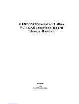
Figure 1-1 illustrates the basic system configuration of a four-processor platform.
Figure 1-1. Diagram of a Typical Intel® 460GX Chipset-based System with AGP
000346e
USB
GXB
Graphi cs
Exp ans io n
Br i dge
Expander
Buses
PXB
PCI
Expansion
Bridge
AGP
4X Mode
Sl ot
GAR T
SRAM
Compatibility
PCI Bus
PI D
Pr ogr ammabl e
Interrupt Device
IFB
I/O and Firmware
Bri dge
SDC
System Dat a
Controller
IDE HDD
IDE CD-ROM
Private Bus
Memory Data and Control Bus
Itanium™ Processor System Bus
Pr oce sso r
Cache
Processor
Cac he
Processor
Cac he
Processor
Cac h e
WXB
Wide PCI
Expansion
Bri dge
2 PCI Buses
3.3V/5.0V,
32-bit, 33 MHz
2 PCI Buses
3.3V, 64-bit, 66 MHz
MAC
MAC
MDC
MDC
MDC
MDC
Memory Subsystem
MAC
MAC
MDC
MDC
MDC
MDC
Memory Subsystem
SAC
System Address
Con t r olle r
Super
I/O
FWH
Firmware
Hub
Firmware
Hub Interface
LPC Interface

Introduction
1-2 Intel® 460GX Chipset Software Developer’s Manual
1.1.1 Component Overview
Table 1-1 lists the 460GX chipset components.
Table 1-1. Intel® 460GX Chipset Components
Component Name Function
SAC 82461GX
System Address
Controller
Interfaces the address and control portion of the Itanium™ processor
system bus and the memory bus. Acts as a host bridge interface to
peripheral I/O devices through four Expander busses.
SDC 82462GX
System Data path
Controller
Interfaces the data portion of the Itanium processor system bus and
the memory bus.
MAC 82463GX
Memory Address
Controller
Provides the SDRAM RAS/CAS/WE/CS generation as well as
redriving the address to the SDRAMs. It is capable of buffering several
commands from the SAC.
MDC 82464GX
Memory Data path
Controller
Multiplexes the data from the SDRAM to the SDC. On reads, it latches
data from the SDRAM, then transfers the data to the SDC. On writes, it
latches the data from the SDC, then writes the data to the SDRAM.
GXB 82465GX
Graphics Expander
Bridge
Provides the control and data interface for an AGP 4X graphics port.
This device attaches to the SAC via two Expander busses which utilize
a special configuration.
WXB 82466GX
Wide and fast PCI
Expander Bridge
Provides the primary control and data interface for two independent
64-bit, 66 MHz PCI interfaces. This device attaches to the SAC via an
Expander bus.
PXB 82467GX
PCI Expander Bridge
Provides the primary control and data interface for two independent
32-bit, 33-MHz PCI interfaces. These two 32-bit interfaces may
operate together to produce a single 64-bit, 33-MHz interface via a
configuration option. This device attaches to the SAC via an Expander
bus.
IFB 82468GX
I/O and Firmware
Bridge
The IFB is a multi-function PCI device implementing a PCI-to-LPC
bridge function, a PCI IDE function, a Universal Serial Bus Host/Hub
function, an SMBus Interface function, Power Management function
and the Firmware Hub interface.
FWH 82802AC
Firmware Hub 8Mb
The FWH component interfaces to the IFB component and provides
firmware storage and security features. Further FWH information can
be found at http://developer.intel.com/design/chipsets/datasheets or by
ordering document 290658.
PID NEC# UPD66566S1-
016
Programmable
Interrupt Device
The PID is an interrupt controller that provides interrupt steering
functions. The PID contains the logic required to support 8259A mode,
APIC mode, and SAPIC mode interrupt controller operations. The PID
interfaces include a PCI bus interface, an APIC bus interface, a serial
IRQ interface, and an interrupt input interface.

Intel® 460GX Chipset Software Developer’s Manual 1-3
Introduction
1.2 Product Features
1.3 Itanium™ Processor System Bus Support
• Full support for the Itanium processor system bus.
— 64-bit data bus.
— 266 MHz data bus frequency.
— Cache line size of 64 bytes.
— Supports SAPIC interrupt protocol.
• Full support for 4-way multiprocessing.
• Parity protection on address and control signals, ECC protection on the data signals.
• GTL+ bus driver technology.
• High performance hardware based on IA-64
architecture
—4.2 GB/s memory bandwidth can
simultaneously support both the full system
bus and the full I/O bus bandwidths
—Architectural support for 64 MB to 64 GB of
SDRAM
—Support for up to four bridge chips that
interface to the 82461GX (SAC) through
four Expander channels, each 30 bits wide
and providing 533 MB/s peak bandwidth
—AGP 4X compatible, via the 82465GX
(GXB) and two Expander channels running
at 266 MHz totaling 1 GB/s peak bandwidth
—Support for two 64-bit, 66-MHz PCI buses
using one 82466GX (WXB) component per
Expander channel
—Support for two independent 32-bit, 33-MHz
PCI buses or one 64-bit, 33-MHz PCI bus via
the 82467GX (PXB) per Expander channel
—Data streaming support between Expanders
and DRAM, up to 533 MB/s per Expander
channel
• Extensive RAS features for mission-critical
needs
—ECC protection on the system bus data
signals
—Memory ECC with single-bit error
correction, double and nibble error detection
—Address and data flows protected by parity
throughout chipset
—ECC bits in DRAM accessible by diagnostics
—Fault recording of multiple errors; sticky
through reset
—JTAG TAP port for debug and boundary scan
capability
—I2C slave interface for viewing and
modifying specific error and configuration
registers
—Bus, memory and I/O performance counters
—Support of ACPI/DMI functions (support is
provided in the IFB)
• High bandwidth system bus for multiprocessor
scalability
—Support of the Intel® Itanium™ processor
64-bit data bus
—Full support for 4-way multiprocessing
—266 MHz data bus frequency
—Cache line size of 64 bytes
—Enhanced defer feature for out-of-order data
delivery using IDS#
—AGTL+ bus driver technology
• Features to support flexible platform
environments
—Hardware compatible with IA-32 binaries
—AGP address space up to 32 GB supported
—Support for Auto Detection of SDRAM
memory type and mixed memory sizes
allowed between rows
—Supports 16-, 64-, 128- and 256-Mbit
DRAM devices
—Full support for the PCI Configuration Space
Enable (CSE) protocol to devices on all
Expander channels
—WXB supports 3.3 volt PCI bus operation
(supports universal and 3.3 volt PCI cards)
and has an Integrated Hot-Plug Controller**
—PCI Rev. 2.2 compliant on the WXB and
PXB
—GXB supports fast writes and 1x, 2x and 4x
data rates
—1 MB or greater of firmware storage
provided by the 82802AC (FWH)
—Interrupt controller, bus-mastering IDE and
Universal Serial Bus supported by the
82468GX (IFB)
—Support of 8259A mode, APIC mode and
SAPIC mode interrupts via the
UPD55566S1-016 (PID) provided by NEC*
**Based on technology licensed from Compaq Computer Corp.

Introduction
1-4 Intel® 460GX Chipset Software Developer’s Manual
1.4 DRAM Interface Support
• SDRAM 3.3 volt, 168-pin DIMM’s are the only memory type supported.
• Support for 64 MB to 64 GB of DRAM.
• Minimum memory size is 64 MB using 16 MB DIMM’s.
• Minimum incremental size is 64 MB using 16 MB DIMM’s.
• Maximum memory size is 16 GB using 128 MB DIMM’s.
• Maximum memory size is 64 GB using 1 GB DIMM’s.
• Only 3.3 volt memory is supported.
• Support for Auto Detection of SDRAM Memory Type.
• Supports 16, 64, 128 and 256 Mbit DRAM devices.
• Mixed memory sizes allowed between rows.
• Staggered CAS-before-RAS refresh (standard SDRAM refresh).
• ECC with single-bit error correction, double and nibble error detection.
• Extensive processor-to-Memory and PCI-to-Memory write data buffering, thus minimizing
the interference of writes on read latency.
1.5 I/O Support
• 4 Expander ports, each 30 bits wide and providing 533 MB/s peak bandwidth.
• Each Expander bus supports a single PXB or WXB. Two Expander busses can be configured
to support a GXB.
• Full support for the PCI Configuration Space Enable (CSE) protocol to devices on all
Expander ports.
• Data streaming support between Expanders and DRAM, up to 533 MB/s per Expander port.
• All outbound memory and I/O reads (except locked reads) are deferred.
• All outbound memory space writes are posted. Outbound I/O space writes are optionally
posted (unless targeting an address with side effects, in which case they are deferred).
• All inbound memory reads are delayed.
• All inbound memory space writes are posted.
• Supports concurrent processor and I/O initiated transactions to main memory.
• Maintains coherency with processors by snooping all inbound transactions to the system bus.
• Supports non-coherent traffic (for AGP), with a direct path to memory bypassing the system
bus.
1.5.1 PXB Features
• Can be configured to provide two independent 32 bit, 33 MHz PCI buses or one 64 bit, 33
MHz PCI bus.
• PCI Rev. 2.2, 5V tolerant (PXB drives 3.3 volts, but is 5.0 volt tolerant).

Intel® 460GX Chipset Software Developer’s Manual 1-5
Introduction
• Parity protection on all PCI signals.
• Data collection & write assembly.
— Combines back-to-back sequential processor-to-PCI memory writes to PCI burst writes.
— Processor to PCI write assembly of full/partial line writes.
• Two outbound read requests containing a total of two cache lines of read data for each PCI bus.
• Supports six outbound write requests containing a total of three cache lines of write data for
each 32 bit PCI bus. Supports 12 outbound write requests containing a total of six cache lines
of write data for a 64 bit PCI bus.
• Supports two delayed inbound read requests.
• Supports the I/O and Firmware Bridge (IFB).
• Supports either internal or external arbitration, allowing additional bus masters, on the PCI
bus.
1.5.2 WXB Features
• Support for two 64 bit, 66 MHz PCI busses.
• 3.3 Volt PCI bus operation (supports Universal and 3.3 Volt PCI cards).
• PCI Specification, Revision 2.2.
• Integrated Hot-Plug controller.
1.5.3 GXB Features
• The GXB is AGP and AGP 4X mode compatible, nominal 66 MHz, 266 MHz, 1 GB/s peak
bandwidth.
• The GXB supports pipelined operation or sideband signals on AGP 4X mode bus.
• AGP address space of 1 GB or 256 MB supported. Also supports 32 GB of GART window, if
4 MB pages are used.
• Supports Fast Writes and 1x, 2x and 4x data rates.
1.6 RAS Features
• ECC coverage of system data bus using the Itanium™ processor SEC/DED ECC code.
Memory is protected using a SEC/DED code which also provides nibble detection capabilities
of 4 bits. All control and address signals are parity protected. Local control buses are parity
protected. The Expander is covered by parity.
• Data flows protected by parity throughout chipset.
• ECC bits in DRAM accessible by diagnostics.
• Fault recording of multiple errors; sticky through reset, but NOT through power-down.
• Memory scrubbing implemented in hardware.
• Boundary test capability through JTAG.
• JTAG TAP port for debug.

Introduction
1-6 Intel® 460GX Chipset Software Developer’s Manual
• I2C Slave Interface will allow viewing and modifying of specific error and configuration
registers.
1.7 Other Platform Components
These 460GX devices provide access to flash space, interrupt collection and legacy features.
1.7.1 I/O & Firmware Bridge (IFB)
The 460GX chipset is designed to work with the IFB south bridge. As part of this support, the PXB
includes an internal PCI arbiter as well as support for an external PCI arbiter. The IFB consists of
an 8259C Interrupt controller, a bus-mastering IDE interface, and a Universal Serial Bus interface.
Devices using IFB are limited to a 32 bit addressing space available for DMA, not the full 44 bits
supported by the Itanium™ processor.
1.7.2 Programmable Interrupt Device (PID)
The PID is a PCI device that gathers interrupts and delivers them from the PCI bus to the system
bus using the SAPIC interrupt protocol. The interrupt will be presented to one of the processors on
the bus for servicing. A 460GX chipset based platform requires at least one PID located on the
compatibility PCI bus. The compatibility PID will handshake with the IFB before delivering a
south bridge/compatibility device interrupt. The same PID may also be used to deliver some
portion of the PCI based interrupts.
The system implementor can choose how many PIDs are used in the platform. If enough interrupt
lines are shared, there need be only one PID in the system; all interrupts in the system would then
be routed to that PID. Each PID has enough interrupt inputs to handle dedicated interrupts from the
cards on two PCI buses. Therefore, using one PID per PXB provides a high performance solution
with minimum routing between PCI buses.
1.8 Reference Documents
In addition to this document, the reader should be familiar with the following reference documents:
• Intel® 460GX Chipset Datasheet
(Document Number: 248703)
• Intel® Itanium™ Processor Hardware Developer’s Manual
(Document Number: 248701)
• Intel® Itanium™ Processor at 800 MHz and 733 MHz Datasheet
(Document Number: 245481)
• Intel® 82460GX Chipset OLGA1 Package, Manufacturing, Mechanical, and Thermal Design
Guide
• PCI Local Bus Specification, Rev 2.2
(http://www.pcisig.com/)
• Accelerated Graphics Port Interface Specification
(http://www.intel.com/technology/agp/agp_index.htm)

Intel® 460GX Chipset Software Developer’s Manual 1-7
Introduction
• JTAG IEEE 1149.1 Specification
(http://www.ieee.com)
• Universal Serial Bus Specification
(http://www.usb.org)
• System Management Bus Specification, Rev. 1.0
• Low Pin Count (LPC) Interface Specification, Rev 1.0
Note: Contact your Intel representative for the latest revision of the documents without document
numbers.
1.9 Revision History
Date Description
June 2001 Initial release.

Introduction
1-8 Intel® 460GX Chipset Software Developer’s Manual
/