Haier 0010518181 User manual

Category
Split-system air conditioners
Type
User manual

This manual is also suitable for

No.0010518181
Installation Manual of Room Air Conditioner
Read this manual before installation
1.Driver
2.Ha
cksaw
3.Hole core d
rill
4.Spanner(17,19 and 26mm)
5.
Torque wrench(17mm,22mm,26mm)
6.Pipe cutter
7.Fla
ring tool
8.Kni
fe
9.Nipper 12.Reamer
10.Gas leakage detector or
soap-and-
water solution
11.Measuring tape
Explain sufficiently the operating means to the user
according to this manual.
A
B
C
D
E
F
G
Optional parts for piping
Mark
Parts name
Non-adhesi
ve tape
Adhesi
ve tape
Saddle(L.S) with scr
ews
Connecting elect
ric cable
for indoor and outdoor
Drain hose
Heating insulating mate
rial
Piping hole c
over
Arrangement of piping directions
Rear left
Rear
right
Left
Below
Right
The marks from to in the figure are the parts numbers.
The distance between the indoor unit and the floor should be
more than 2m.
A
G
Attention must be paid to
the rising up of drain hose
mc5 na
h
t er
om
m
c
0
1
n
a
h
t
e
r
o
m
m
c
0
1
n
ah
t
e
r
o
m
A
C
No. Accessory parts
Remote controller
R-03 d
ry battery
Mounting plate
Drain hose
Steel nail, cement
Screw
Plastic cap
Drain-elbow
Cover
Cushion
1
1
2
3
4
5
6
7
8
9
10
2
1
1
6
4
1
1
4
1
Number
of
articles
Accessory parts
4X50
4X25
Pipe supporting plate
11
Connecting cable
1
m
c
0
1
n
a
h
t
e
r
o
m
m
c
0
6
n
a
h
t
e
r
o
m
m
c
5
1
n
a
h
t
e
r
o
m
m
c
0
1
n
a
h
t
e
r
o
m
D
E
Note:Cooling only units don't have Drain-elbow
Drawing for the installation of indoor and outdoor units
Necessary Tools for Installation
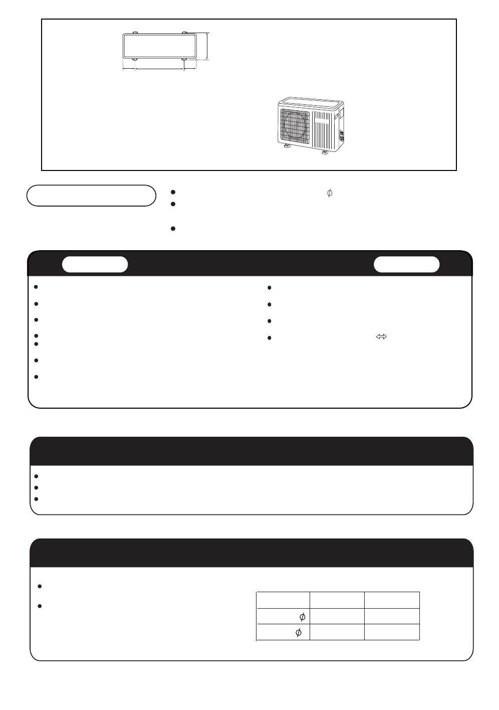
Fixing of outdoor unit
Indoor Unit
Selection of Installation Place
Power Source
Selection of pipe
Outdoor Unit
Fix the unit to concrete or block with bolts( 10mm) and nuts firmly and horizontally.
When fitting the unit to wall surface, roof or rooftop, fix a supporter surely with nails
or wires in consideration of earthquake and strong wind.
If vibration may a
ffect the house, fix the unit by attaching a vibration-proof mat.
Place, robust not causing vibration, where the body can be supported
su
fficiently.
Place, not a
ffected by heat or steam generated in the vicinity, where
inlet and outlet of the unit are not disturbed.
Place, possible to drain easi
ly, where piping can be connected with the
outdoor unit.
Place, where cold air can be spread in a room entire
ly.
Place, nearby a power receptacle, with enough space around. (Refer
to drawings).
Place where the distance of more than lm from televisions, radios,
wireless apparatuses and fluorescent lamps can be left.
In the case of fixing the remote controller on a wall, place where the
indoor unit can receive signals when the fluorescent lamps in the room
are lightened.
Place, which is less a
ffected by rain or direct sunlight and is
su
fficiently ventilated.
Place, possible to bear the unit, where vibration and noise are
not increased.
Place, where discharged wind and noise do not cause a
nuisance to the neighbors.
Place, where a distance marked is available as illustrated
in the above figure.
Before inserting power plug into receptacle, check the voltage without fail
. The power source is the same as the corresponding name plate.
Install an exclusive branch circuit of the pow
er.
A receptacle shall be set up in a distance where the power cable can be reached. Do not extend the cable by cutting it.
To this unit, both liquid and gas pipes shall be insulated
as they become Iow temperature in operation.
Use optional parts for piping set or pipes covered with
equivalent insulation material.
2
HSU-12HG13-B
Floor fixing dimensions
of the outdoor unit
(Unit:mm)
HSU-09HG13-B
140 140415
082
Liquid pipe ( )
For 09
6.35mm(1/4")
Gas pipe ( ) 9.52mm(3/8")
For 12
6.35mm(1/4")
12.7mm(1/2")
Indoor unit
1.Fitting of the Mounting Plate and Positioning of the wall Hole
2.Making a Hole on the Wall and Fitting the Piping Hole Cover
When the mounting plate is first fixed
When the mounting plate is fixed side bar and lintel
1.Carry out, based on the neighboring pillars or lintels, a proper leveling for the plate to be
fixed against the wall, then temporarily fasten the plate with one steel nail.
2. Make sure once more the proper level of the plate, by hanging a thread with a weight from
the central top of the plate, then fasten securely the plate with the attachment steel nail.
3. Find the wall hole location A using a measuring tape
Refer to the previous article, " When the mounting plate is first fixed ", for the
position of wall hole.
Fix to side bar and lintel a mounting bar, Which is separately sold, and then fasten
the plate to the fixed mounting bar.
Make a hole of 60 mm in diameter,
slightly descending to outside the wall.
Install piping hole cover and seal it
off with putty after installation
(Section of wall hole)
Piping hole pipe
Outdoor side
Thickness
of wall
Indoor side
Wall hole
60mm
3.Installation of the Indoor Unit
Drawing of pipe
[ Rear piping ]
Draw pipes and the drain hose, then fasten them with the adhesive tape
[ Left Left-rear piping ]
In case of left side piping, cut away, with a nipper, the lid for left piping.
In case of left-rear piping, bend the pipes according to the piping direction to the mark of hole for left-rear
piping which is marked on heat insulation materials.
3
G
Indoor unit
A=145mm
B= 60mm
30mm
Indoor unit
Fixing the indoor unit body
[Other direction piping]
Indoor/outdoor electric cable and drain hose must be bound with refrigerant piping by protecting tape.
Cut awa
y, with a nipper, the lid for piping according to the piping direction and then bend the pipe according
to the position of wall hole. When bending, be careful not to crash pipes.
Connect beforehand the indoor/outdoor electric cable, and then pull out the connected to the heat insulation
of connecting part speciall
y.
Hang surely the unit body onto the upper notches of the
mounting plate. Move the body from side to side to verify
its secure fixing.
In order to fix the body onto the mounting plate,hold up
the body aslant from the underside and then put it down
perpendicularl
y.
1. Insert the drain hose into the dent of heat insulation materials of indoor unit.
2. Insert the indoor/outdoor electric cable from backside of indoor unit, and pull it out on the front side, then
connect them.
3. Coat the flaring seal face with refrigerant oil and connect pipes.
Cover the connection part with heat insulation materials closel
y, and make sure fixing with adhesive tape
4
Heat insulation
material
Drain hose
Piping
Indoor/outdoor
electric cable
Lid for right piping
Lid for under piping
Lid for left piping
Fix with adhesive tape
mounting plate
Unloading of indoor unit body
When you unload the indoor unit,please use your hand to arise
the body to leave agraffe,then lift the bottom of the body outward
slightly and lift the unit aslant until it leaves the mounting plate.
agraffe
mounting plate
Indoor unit
1. If the supply cord is damaged, it must be replaced by the manufacturer or its service agent or a similar
qualified person.
The type of connecting wire is H05/07RN-F or 245IEC57(YZW).
2. If the fuse on PC board is broken please change it with the type of T. 3.15A/250V.
3. The wiring method should be in line with the local wiring standard.
4. After installation, the power plug should be easily reached.
5
When connecting the cable before installing the indoor unit
Insert the cable from the back side of the unit, then pull it out on the front side.
Loosen the scr
ews and insert the cable ends fully into terminal block, then tighten the screws.
Pull the ca
ble slightly to make sure the cables have been properly inserted and tightened.
After the ca
ble connection, never fail to fasten the connected cable with the wiring cover.
Note
: When connecting the cable, confirm the terminal number of indoor and outdoor units carefully. If wiring
is not correct, proper ope
ration can not be carried out and will cause defect.
5.
A breaker should be incorporated into fixed wiring. The breaker should be all-pole switch and the
distance between its two contacts should be not less than 3mm.
Connecting the indoor/outdoor Electric Cable
Removing the wiring cover
Remove terminal cover at right bottom corner of indoor unit, then
take o
ff wiring cover by removing its screws.
When connecting the cable after installing the indoor unit
1. Insert from outside the room cable into left side of the wall hole, in which
the pipe has already
existed.
2. Pull out the cable on the front side, and connect the cable making a loop.
connecting wiring:
-mod 09-12:
Power cable:
-mod 09-12:
3G1.0mm
HSU-09HG13-B
HSU-12HG13-B
LN
:
3G1.0mm
34:
2X0.75mm
Indoor unit
Outdoor unit
3
4
Indoor unit
Outdoor unit
3
4
Outdoor unit
1.Installation of Outdoor Unit
3.Connection
4.Atta
ching Drain-Elbow
2.Connection of pipes
Install according to
To bend a pipe, give the roundness as large as possible not to crush the pipe
Connecting the pipe of gas side first makes working easier.
The max vertical distance between the indoor unit and the outdoor unit is 5 m.
Use the same method on indoor unit
. Loosen the screws on terminal block and insert the plugs fully into
te
rminal block, then tighten the screws.
If wi
ring is not correct, proper operation can not be carried out and controller may be damaged.
If the drain-elbow is used, please attach it as
figure. (Note: Only for heat pump unit.)
Dr
awing for the installation of indoor and outdoor units
Inse
rt the cable according to terminal number in the same manner as the indoor unit.
Fix the ca
ble with a clamp.
Half union
Flare nut
Spanner
Torque wrench
6
Outdoor unit
Forced fastening without careful centering
may damage the threads and cause a
leakage of ga
s.
Be careful that matters, such as wastes of sands, etc. shall not enter the pipe.
Pipe Diameter ( )
Liquid side 6.35mm(1/4")
Gas side 9.52mm(3/8")
Fastening torque
18N.m
42N.m
Gas side 12.7mm(1/2")
50N.m
Outdoor unit
5.Purging Method:
7
Push the air out of the indoor unit
and piping as followes:
(1) Remove the valve cap on 2-way
valve in outdoor unit.
(2) Loosen by 1/2 turn the flare nut of
gas pipe, which is conneted to
3-way valve.
(3) Loosen 2-way valve by 90
o
using
hexagon wrench, and after approx.
10 sec tighten it up. Gas comes out
through flare nut on wide pipe. If no
gas is discharged, tighten flare nut
with specified torque.
(4) Open 2-way and 3-way valves
using specified torque.
(5)
Tighten the caps on the valves
with specified torque.
Valve rod
Valve cap
7-9
20-25
Tighten torque N.m
When connecting pipe exceeds 5 meters, 20g refrigerant
shall be added per exceeding meter . Charge according to the following list.
Piping length
Additional amount
5m 7m
No need
40g
During this procedure, 50g refrigerant will be discharged in piping.
(This must be strictly controlled within 90
o
and 10 sec.)
Brand new outdoor unit is charged 50g
more refrigerant than regulated
weight. Only for first installation, this extra 50g can be used to purge air
in pipes.
Note: When extending piping, air inside piping shall be removed by using external
refrigerant gas, charge according to the following list.
10m
100g
HSU-09HG13-B
3-way valve
2-
way valve
6.35mm(1/4")
9.52mm(3/8")
for 9k 12k
HSU-12HG13-B
12.7mm(1/2")
It becomes high midway.
The end is immersed
in
water.
It
waves. The gap with the ground
is too small
Less than 5cm
There is the bad smell
from a ditch
1.Power Source Installation
2.Cutting and Flaring
Work of Piping
3.On Drainage
Che
ck for Installation and Test Run
Check Items for Test Run
The power source must be exclusively used for air conditioner. (Over I0A)
In the case of installing an air conditioner in a moist plac
e, please install an
ea
rth leakage breaker.
For installation in other places, use a circuit breaker as far as possible.
Pipe cutting is car
ried out with a pipe cutter and burs must be removed.
After inse
rting the flare nut, flaring work is carried out.
Please install the d
rain hose so as to be downward slope without fail.
Please don't do the d
rainage as shown below.
Please pour
water in the drain pan of the indoor unit, and confirm that drainage is
carried out surely to outdoor.
In case that the attached d
rain hose is in a room, please apply heat insulation
to it without fail.
Please kindly
explain to our customers how to operate through the instruction manual.
Gas leak from pipe connecting?
Heat insulation of pipe connecting?
Are the connecting wi
rings of
indoor and outdoor fi
rmly inserted
to the te
rminal block?
Is the connecting wi
ring of indoor
and outdoor fi
rmly fixed?
Is d
rainage securely carried out?
Is the ea
rth line securely
connected?
Is the indoor unit securely fi
xed?
Is p
ower source voltage abided
by the code?
Is there a
ny noise?
Put che
ck mark in boxes
Is the lamp no
rmally lighting?
Are cooling and heating (when
in heat pump) per
formed normally?
Is the ope
ration of room temperature
regulator no
rmal?
8
Correct
Incorrect
Lean Damage of flare Crack Partial Too outside
Flare tooling die
A
Liquid side
Pipe diameter( )
Size A(mm)
6.35mm(1/4")
9.52mm(3/8")
0.8~1.5
1.0~1.8
Gas side
Gas side 12.7mm(1/2")
1.2~2.0
  • Page 1 1
  • Page 2 2
  • Page 3 3
  • Page 4 4
  • Page 5 5
  • Page 6 6
  • Page 7 7
  • Page 8 8

Haier 0010518181 User manual

Category
Split-system air conditioners
Type
User manual
This manual is also suitable for

Ask a question and I''ll find the answer in the document

Finding information in a document is now easier with AI