JVC RX-ES1SL User manual

Category
AV receivers
Type
User manual
LVT1002-006A
[J]
HOME THEATER RECEIVER
RX-ES1SL
INSTRUCTIONS
For Customer Use:
Enter below the Model No. and Serial No.
which are located either on the rear, bot-
tom or side of the cabinet. Retain this
information for future reference.
Model No.
Serial No.
cover.RX-ES1SL[J]1 03.3.17, 3:20 PM1
Warnings, Cautions and Others/
Mises en garde, précautions et indications diverses
CAUTION: TO REDUCE THE RISK OF ELECTRIC SHOCK,
DO NOT REMOVE COVER (OR BACK).
NO USER SERVICEABLE PARTS INSIDE.
REFER SERVICING TO QUALIFIED SERVICE PERSONNEL.
RISK OF ELECTRIC SHOCK
DO NOT OPEN
The lightning flash with arrowhead symbol,
within an equilateral triangle is intended to
alert the user to the presence of uninsulated
"dangerous voltage" within the product's
enclosure that may be of sufficient
magnitude to constitute a risk of electric
shock to persons.
The exclamation point within an equilateral
triangle is intended to alert the user to the
presence of important operating and
maintenance (servicing) instructions in the
literature accompanying the appliance.
CAUTION
Caution –– switch!
Disconnect the mains plug to shut the power off completely. The
switch in any position does not disconnect the mains line.
The power can be remote controlled.
Attention –– Commutateur !
Déconnecter la fiche de secteur pour couper complètement le
courant. Le commutateur ne coupe jamais complètement la
ligne de secteur, quelle que soit sa position. Le courant peut être
télécommandé.
For Canada/pour Le Canada
THIS DIGITAL APPARATUS DOES NOT EXCEED THE CLASS
B LIMITS FOR RADIO NOISE EMISSIONS FROM DIGITAL
APPARATUS AS SET OUT IN THE INTERFERENCE-CAUSING
EQUIPMENT STANDARD ENTITLED “DIGITAL APPARATUS,”
ICES-003 OF THE DEPARTMENT OF COMMUNICATIONS.
CET APPAREIL NUMERIQUE RESPECTE LES LIMITES DE
BRUITS RADIOELECTRIQUES APPLICABLES AUX
APPAREILS NUMERIQUES DE CLASSE B PRESCRITES
DANS LA NORME SUR LE MATERIEL BROUILLEUR;
“APPAREILS NUMERIQUES”, NMB-003 EDICTEE PAR LE
MINISTRE DES COMMUNICATIONS.
For Canada/pour le Canada
CAUTION: TO PREVENT ELECTRIC SHOCK, MATCH WIDE
BLADE OF PLUG TO WIDE SLOT, FULLY INSERT
ATTENTION: POUR EVITER LES CHOCS ELECTRIQUES,
INTRODUIRE LA LAME LA PLUS LARGE DE LA FICHE DANS LA
BORNE CORRESPONDANTE DE LA PRISE ET POUSSER
JUSQUAU FOND
Note to CATV system installer:
This reminder is provided to call the CATV system installers
attention to Section 820-40 of the NEC which provides
guidelines for proper grounding and, in particular, specifies that
the cable ground shall be connected to the grounding system
of the building, as close to the point of cable entry as practical.
CAUTION
To reduce the risk of electrical shocks, fire, etc.:
1. Do not remove screws, covers or cabinet.
2. Do not expose this appliance to rain or moisture.
ATTENTION
Afin d’éviter tout risque d’électrocution, dincendie, etc.:
1. Ne pas enlever les vis ni les panneaux et ne pas ouvrir le
coffret de lappareil.
2. Ne pas exposer lappareil à la pluie ni à lhumidité.
WARNING: TO REDUCE THE RISK OF FIRE
OR ELECTRIC SHOCK, DO NOT EXPOSE
THIS APPLIANCE TO RAIN OR MOISTURE.
safety.RX-ES1SL[J]1 03.3.27, 3:07 PM1
1
Table of Contents
Parts identification ............................................................2
Getting started ..................................................................4
Before installation ................................................................................ 4
Checking the supplied accessories ..................................................... 4
Putting batteries in the remote control ................................................. 4
Connecting the FM and AM antennas ................................................. 5
Connecting the speakers ..................................................................... 6
Connecting video components ............................................................ 7
Connecting the power cord ................................................................ 10
Basic operations .............................................................11
1 Turn on the power .......................................................................... 11
2 Select the source to play ................................................................ 11
3 Adjust the volume .......................................................................... 12
Selecting the digital decode mode ..................................................... 12
Turning off the sounds temporarily—Muting ...................................... 13
Turning off the power with the Sleep Timer ....................................... 13
Changing the display brightness ........................................................ 14
Speaker settings .............................................................15
Setting the speakers information automatically
—Smart Surround Setup ............................................................. 15
Setting the speakers and subwoofer information quickly
—Quick Setup ............................................................................. 16
Setting the speakers and subwoofer information manually
—Manual Setup ........................................................................... 17
Basic settings ..................................................................19
Operating procedure .......................................................................... 19
Setting the digital Input (DIGITAL IN) terminals
—DIGITAL IN ............................................................................... 19
Setting Auto Surround—AUTO SR .................................................... 20
Setting the video component input mode
—DVD VIDEO/DBS VIDEO ......................................................... 20
Sound adjustments .........................................................21
Operating procedure .......................................................................... 21
Adjusting the tone—BASS, TREBLE ................................................. 21
Adjusting the subwoofer output level—SUBWFR .............................. 21
Adjusting the front speakers output balance—BAL ........................... 22
Reinforcing the bass—B.BOOST ...................................................... 22
Attenuating the input signal—ATT ..................................................... 22
Tuner operations .............................................................23
Tuning in to stations manually............................................................ 23
Using preset tuning ............................................................................ 23
Selecting the FM reception mode ...................................................... 24
Creating realistic sound fields .......................................25
Reproducing theater ambience .......................................................... 25
Introducing the Surround/DSP modes ................................................ 25
About relations between speaker layout
and Surround/DSP modes ........................................................... 27
Using Surround modes ...................................................................... 27
Using DSP modes ............................................................................. 29
Using the DVD MULTI playback mode ........................... 31
Activating the DVD MULTI playback mode .......................................... 31
Adjusting the speaker output level ...................................................... 31
AV COMPLU LINK remote control system ....................32
Operating other JVC products .......................................34
Operating other manufacturers’ equipment ...................
35
Troubleshooting ..............................................................38
Specifications ..................................................................40
01-10.RX-ES1SL[J]1 03.3.24, 1:28 PM1
2
Remote control
Parts identification
See pages in parentheses for details.
1 Standby/on buttons (11, 34 – 37)
AUDIO, DVD , VCR , DBS , TV
2 Source selecting buttons (11)
DVD, VCR, DBS, TV, DVD MULTI, FM/AM
3 CHANNEL +/– buttons (34 – 37)
4 TV VOL (volume) +/– buttons (34, 37)
5 Operating buttons for video components (34, 36)
4, 3, ¢, 1, 7, 8, ¡
Operating buttons for tuner (23, 24)
TUNING 9, TUNING (, FM MODE, MEMORY
6 SLEEP button (13)
7 DIMMER button (14)
8 BASS BOOST button (22)
9 SMART S (surround). SETUP button (15)
p EFFECT button (30)
q TEST button (28 – 30)
w Adjusting buttons for speaker and subwoofer output levels
(21, 28, 30, 31)
SUBWFR (subwoofer) +/–, CENTER +/–, SURR L (Left
surround) +/–, SURR R (right surround) +/–
e TV/VIDEO button (34, 37)
r MUTING button (13)
t VOLUME +/– buttons (12)
y Mode selector
DVD, AUDIO/TV/VCR/DBS
u Numeric buttons for adjusting tone (21)
BASS 9/(, TREBLE 9/(
Numeric buttons for selecting preset channels (24)
Numeric buttons for operating video components (34 – 37)
i ANALOG/DIGITAL INPUT button (11, 12)
o TONE button (21)
; A (audio).POSITION button (22)
a DECODE button (12)
s SURROUND button (27, 29, 30)
* Buttons shown in half tone color are used for operating JVC DVD
player.
If these buttons cannot be functioned normally, use a remote
control supplied with your DVD player. See the instruction
supplied with the DVD player for details.
When operating this receiver, always set the mode selector
(y) to “AUDIO/TV/VCR/DBS”
2
r
t
5
3
4
1
e
y
6
7
8
9
p
q
w
u
i
o
a
;
s
H
DVD-AUDIO
1
2
3
4
5
6
7
8
9
+10
RM-SQPES1J
REMOTE CONTROL
To open the cover of the remote
control, push here then slide
downward.
01-10.RX-ES1SL[J]1 03.3.27, 3:09 PM2
3
Front panel
1 STANDBY/ON button and STANDBY lamp (11)
2 DIMMER button (14)
3 SETTING button (16, 17, 19)
4 ADJUST button (21, 28, 30, 31)
5 SURROUND button (28, 30)
6 Display window (see below)
7 Source indicators
DVD MULTI, DVD, DBS, VCR, TV, FM/AM
8 SET button (16, 17, 19, 21, 29, 30, 31)
TUNER PRESET button (24)
9 Remote sensor (4)
p SOURCE SELECTOR (11)
MULTI JOG (16, 17, 19, 21, 24, 28 – 31)
q MASTER VOLUME control (12)
w PHONES jack (12)
Display window
1 Signal format indicators (11, 13)
ANALOG, LPCM (Linear PCM), DOLBY D (Dolby Digital), DTS
2 Signal and speaker indicators (14)
3 DSP indicator (26, 29, 30)
4 PLII indicator (25)
5 HP (headphone) indicator (12)
6 SLEEP indicator (13)
7 BASS BOOST indicator (22)
8 Tuner operation indicators (23)
TUNED, ST (stereo)
9 AUTO MUTING indicator (24)
p INPUT ATT (attenuator) indicator (22)
q AUTO SR (surround) indicator (20)
w Main display
e Volume level indicator (11)
r A (audio).POSITION indicator (22)
Rear panel
1 ANTENNA terminals (5)
2 DVD IN terminals (7, 8)
FRONT, CENTER, SURR (REAR), SUBWOOFER
3 COMPONENT VIDEO terminals (7 – 9)
DVD IN, DBS IN, MONITOR OUT
4 VIDEO terminals (7 – 9)
DVD IN, DBS IN, VCR OUT (REC)/IN (PLAY), MONITOR OUT
5 DIGITAL IN terminals (10)
DIGITAL 1 (DVD) , DIGITAL 2 (DBS), DIGITAL 3 (TV)
See pages in parentheses for details.
6 Speaker terminals (6)
FRONT SPEAKERS, SURROUND SPEAKERS, CENTER
SPEAKER
7 AV COMPULINK-III terminals (32)
8 AUDIO terminals (8, 9)
DBS IN, VCR OUT (REC)/IN (PLAY), TV IN
9 SUBWOOFER OUT jack (6)
Parts identification
COAXIAL
AM LOOP
ANTENNA
FM 75
AM EXT
VIDEO
AUDIO
COMPONENT VIDEO
SUBWOOFER
OUT
DIGITAL IN
DIGITAL 3
(TV)
DIGITAL 2 (DBS)
DIGITAL 1
(DVD)
DVD
IN
DVD
IN
DVD IN
FRONT
SURR (REAR)
TVVCRDBS
AV
COMULINK-III
ININ
IN
(PLAY)
OUT
(REC)
RIGHT LEFT
SUB-
WOOFER
CENTER
RL
L
R
DBS IN MONITOR
OUT
DBS
IN
VCR
MONITOR OUT
VIDEO
OUT
(REC)
IN
(PLAY)
CENTER
SPEAKER
SURROUND
SPEAKERS
RIGHT LEFT RIGHT LEFT
FRONT
SPEAKERS
CAUTION:
SPEAKER
IMPEDANCE
8
~
16
Y
P
B
P
R
S-VIDEO
2
1
3 4 5 6
98
7
STANDBY / ON STANDBY
DIMMER SETTING ADJUST SURROUND
DVD MULTI DVD DBS VCR TV FM / AM
SET / TUNER PRESET
SOURCE SELECTOR MASTER VOLUME
PHONES
/ MULTI JOG
6
8
9
p
7
q
5
4
3
2
1
w
01-10.RX-ES1SL[J]1 03.3.24, 1:28 PM3
4
Getting started
Putting batteries in the remote control
Before using the remote control, put two supplied batteries first.
1
Press and slide the
buttery cover on the back
of the remote control.
2
Insert batteries.
Make sure to match the polarity:
(+) to (+) and (–) to (–).
3
Replace the cover.
If the range or effectiveness of the remote control decreases, replace
the batteries. Use two R6P(SUM-3)/AA(15F) type dry-cell batteries.
Supplied butteries are for initial setup. Replace for continued use.
CAUTION:
Follow these precautions to avoid leaking or cracking cells:
Place batteries in the remote control so they match the polarity:
(+) to (+) and (–) to (–).
Use the correct type of batteries. Batteries that look similar may
differ in voltage.
Always replace both batteries at the same time.
Do not expose batteries to heat or flame.
When using the remote control, aim the remote control directly at the
remote sensor on the front panel.
Before installation
General Precautions
DO NOT insert any metal object into the unit.
DO NOT disassemble the unit or remove screws, covers, or cabinet.
DO NOT expose the unit to rain or moisture.
Locations
Install the unit in a location that is level and protected from moisture.
The temperature around the unit must be between 23˚F and 95˚F (–
5˚C and 35˚C).
Make sure there is good ventilation around the unit. Poor ventilation
could cause overheating and damage the unit.
Handling the unit
DO NOT touch the power cord with wet hands.
DO NOT pull on the power cord to unplug the cord. When
unplugging the cord, always grasp the plug so as not to damage the
cord.
Keep the power cord away from the connecting cords and the
antenna. The power cord may cause noise or screen interference. It
is recommended to use a coaxial cable for antenna connection,
since it is well-shielded against interference.
When a power failure occurs, or when you unplug the power cord,
the preset settings such as preset FM or AM channels and sound
adjustments may be erased in a few days.
Checking the supplied accessories
Check to be sure you have all of the following supplied accessories.
The number in parentheses indicates the quantity of each piece
supplied.
Remote control (1)
Batteries (2)
AM loop antenna (1)
FM antenna (1)
Digital coaxial cord (1)
If anything is missing, contact your dealer immediately.
Remote sensor
01-10.RX-ES1SL[J]1 03.3.24, 1:28 PM4
5
NOTES
If the AM loop antenna wire is covered with vinyl,
remove the vinyl while twisting it as shown on the
right.
Make sure the antenna conductors do not touch any
other terminals, connecting cords and power cord.
This could cause poor reception.
Snap the tabs on the loop
into the slots of the base to
assemble the AM loop
antenna.
Connecting the FM and AM antennas
AM loop antenna
(supplied)
If AM reception is poor, connect an outdoor single vinyl-
covered wire (not supplied).
AM antenna connection
Connect the AM loop antenna supplied to the AM LOOP terminals.
Connect the white cord to the AM EXT terminal, and the black cord to
H terminal.
Turn the loop until you have the best reception.
If the reception is poor, connect an outdoor single vinyl-covered
wire (not supplied) to the AM EXT terminal. Keep the AM loop
antenna connected.
FM antenna connection
Connect the FM antenna supplied to the FM 75 COAXIAL terminal
as temporary measure.
Extend the supplied FM antenna horizontally.
If the reception is poor, connect an outdoor FM antenna (not
supplied). Before attaching a 75 coaxial cable with a connector,
disconnect the supplied FM antenna.
If FM reception is poor, connect
outdoor FM antenna (not supplied).
FM antenna (supplied)
Getting started
CONTINUED ON THE NEXT PAGE
01-10.RX-ES1SL[J]1 03.3.24, 1:28 PM5
6
Getting Started
Connecting the speakers
Turn off all components before connections.
Speaker Layout Diagram
After connecting the front, center and surround speakers, and/or a subwoofer, set the speaker setting information properly to obtain the best
possible surround effect. For details, see pages 15 to 18.
Connecting the front, center, and surround speakers
For each speaker, connect the (+) and (–) terminals on the rear panel
to the (+) and (–) terminals marked on the speakers respectively.
1
Twist and remove the insulation at the end of each
speaker cord (not supplied).
2
Press and hold the clamp of the speaker terminal (1),
then insert the speaker cord (2).
3
Release the finger from the clamp.
CAUTION:
Use speakers with the SPEAKER IMPEDANCE indicated by the
speaker terminals.
DIGITAL
SURROUND
DIGITAL
PRO LOGIC
RX-ES1 HOME CINEMA CONTROL CENTER
STANDBY / ON STANDBY
TV DIRECT SETTING ADJUST SURROUND
DVD MULTI DVD STB VCR TV FM / AM
SET / TUNER PRESET
SOURCE SELECTOR MASTER VOLUME
PHONES
/ MULTI JOG
Center
speaker
Subwoofer
Left front
speaker
Left surround
speaker
Right front
speaker
Right surround
speaker
RX-ES1SL
Powered subwoofer
COAXIAL
AM LOOP
ANTENNA
FM 75
AM EXT
VIDEO
AUDIO
COMPONENT VIDEO
SUBWOOFER
OUT
DIGITAL IN
DIGITAL 3
(TV)
DIGITAL 2 (DBS)
DIGITAL 1
(DVD)
DVD
IN
DVD
IN
DVD IN
FRONT
SURR (REAR)
TVVCRDBS
AV
COMULINK-III
ININ
IN
(PLAY)
OUT
(REC)
RIGHT LEFT
SUB-
WOOFER
CENTER
RL
L
R
DBS IN MONITOR
OUT
DBS
IN
VCR
MONITOR OUT
VIDEO
OUT
(REC)
IN
(PLAY)
CENTER
SPEAKER
SURROUND
SPEAKERS
RIGHT LEFT RIGHT LEFT
FRONT
SPEAKERS
CAUTION:
SPEAKER
IMPEDANCE
8
~
16
Y
P
B
P
R
S-VIDEO
SUBWOOFER
OUT
CENTER
SPEAKER
SURROUND
SPEAKERS
RIGHT LEFT RIGHT LEFT
FRONT
SPEAKERS
CAUTION:
SPEAKER
IMPEDANCE
8
~
16
1
2
1
2
3
A
B
C
D
E
Connecting the subwoofer
By connecting a subwoofer, you can enhance the bass or reproduce
the original LFE signals recorded in the digital software.
Connect the input jack of a powered subwoofer to the
SUBWOOFER OUT jack on the rear panel, using a cord
with RCA pin plugs (not supplied).
• Refer also to the manual supplied with your subwoofer.
NOTE
You can place a subwoofer wherever you like since bass sound is
non-directional. Normally place it in front of you.
A To center speaker
B To right surround speaker
C To left surround speaker
D To right front speaker
E To left front speaker
01-10.RX-ES1SL[J]1 03.3.24, 1:28 PM6
7
Connecting video components
Getting started
Turn off all components before making connections.
Illustrations of the input/output terminals are typical examples. When you connect other components, refer also to their manuals since the
terminal names actually printed on the rear vary among different components.
Notes for video connection:
You can use composite video cord or S-video cord for connecting the VCR to this receiver.
You can use component video cord in addition to composite video cord and S-video cord for connecting your DVD player, TV and DBS tuner
to this receiver.
• By using S-video cord or component video cord, you can get a better picture quality—in the order: composite < S-video < component.
To view the picture from the DVD player, DBS tuner or VCR on your TV, connect your TV to this receiver using the same type of cord for
connecting the DVD player, DBS tuner or VCR to this receiver.
CONTINUED ON THE NEXT PAGE
DVD player connection
When connecting a DVD player with stereo output jacks:
A
VIDEO
COMPONENT VIDEO
SUBWOOFER
OUT
DIGITAL IN
DIGITAL 3
(TV)
DIGITAL 2 (DBS)
DIGITAL 1
(DVD)
DVD
IN
DVD
IN
DVD IN
FRONT
SURR (REAR)
TV
IN
RIGHT LEFT
SUB-
WOOFER
CENTER
RL
DBS IN MONITOR
OUT
DBS
IN
VCR
MONITOR OUT
VIDEO
OUT
(REC)
IN
(PLAY)
CENTER
SPEAKER
SURROUND
SPEAKERS
RIGHT LEFT RIGHT LEFT
FRONT
SPEAKERS
CAUTION:
SPEAKER
IMPEDANCE
8
~
16
Y
P
B
P
R
S-VIDEO
VIDEO
COMPONENT VIDEO
DVD
IN
DVD IN DBS IN MONITOR
OUT
DBS
IN
VCR
MONITOR OUT
VIDEO
OUT
(REC)
IN
(PLAY)
Y
P
B
PR
DVD
IN
FRONT
SURR (REAR)
RIGHT LEFT
SUB-
WOOFER
CENTER
RL
DVD Player
S-VIDEO
Connect using one of the
video terminals.
Component video cord (not supplied)
Composite video cord (not supplied)
S-video cord (not supplied)
Stereo audio cord (not supplied)
To front right channel audio output
To front left channel audio output
01-10.RX-ES1SL[J]1 03.3.24, 1:28 PM7
8
Getting started
When connecting a DVD player with its analog discrete output jacks (5.1-channel reproduction—see page 31):
AM LOOP
ANTENNA
T
VIDEO
AUDIO
COMPONENT VIDEO
SUBWOOFER
OUT
DIGITAL IN
DIGITAL 3
(TV)
DIGITAL 2 (DBS)
DIGITAL 1
(DVD)
DVD
IN
DVD
IN
DVD IN
FRONT
SURR (REAR)
TVVCR
IN
IN
(PLAY)
OUT
(REC)
RIGHT LEFT
SUB-
WOOFER
CENTER
RL
DBS IN MONITOR
OUT
DBS
IN
VCR
MONITOR OUT
VIDEO
OUT
(REC)
IN
(PLAY)
CENTER
SPEAKER
SURROUND
SPEAKERS
RIGHT LEFT RIGHT LEFT
FRONT
SPEAKERS
CAUTION:
SPEAKER
IMPEDANCE
8
~
16
Y
P
B
P
R
S-VIDEO
VIDEO
COMPONENT VIDEO
DVD
IN
DVD IN DBS IN MONITOR
OUT
DBS
IN
VCR
MONITOR OUT
VIDEO
OUT
(REC)
IN
(PLAY)
Y
P
B
P
R
DVD
IN
FRONT
SURR (REAR)
RIGHT LEFT
SUB-
WOOFER
CENTER
RL
DVD Player
S-VIDEO
Component video cord (not supplied)
Composite video cord (not supplied)
S-video cord (not supplied)
Stereo audio cord (not supplied)
Monaural audio cord (not supplied)
To front right channel audio output
To front left channel audio output
To center channel audio output
To surround left channel audio
output
To surround right channel audio
output
To subwoofer output
Connect using one of the
video terminals.
AL
AM LOOP
ANTENNA
AM EXT
VIDEO
AUDIO
COMPONENT VIDEO
SUBWOOFER
OUT
DIGITAL IN
DIGITAL 3
(TV)
DIGITAL 2 (DBS)
DIGITAL 1
(DVD)
DVD
IN
DVD
IN
DVD IN
FRONT
SURR (REAR)
TVVCRDBS
III
ININ
IN
(PLAY)
OUT
(REC)
RIGHT LEFT
SUB-
WOOFER
CENTER
RL
L
R
DBS IN MONITOR
OUT
DBS
IN
VCR
MONITOR OUT
VIDEO
OUT
(REC)
IN
(PLAY)
CENTER
SPEAKER
SURROUND
SPEAKERS
RIGHT LEFT RIGHT LEFT
FRONT
SPEAKERS
CAUTION:
SPEAKER
IMPEDANCE
8
~
16
Y
P
B
PR
S-VIDEO
LEFT
RIGHT
AUDIO
OUT IN
AUDIO
TVVCRDBS
ININ
IN
(PLAY)
OUT
(REC)
L
R
VCR
VIDEO
DVD
IN
DBS
IN
VCR
MONITOR OUT
VIDEO
OUT
(REC)
IN
(PLAY)
S-VIDEO
VCR connection
Connect using one of the video
terminals.
Composite video cord (not supplied)
S-video cord (not supplied)
Stereo audio cord (not supplied)
01-10.RX-ES1SL[J]1 03.3.24, 1:28 PM8
9
Getting started
CONTINUED ON THE NEXT PAGE
COAXIAL
AM LOOP
ANTENNA
FM 75
AM EXT
VIDEO
AUDIO
COMPONENT VIDEO
SUBWOOFER
OUT
DIGITAL IN
DIGITAL 3
(TV)
DIGITAL 2 (DBS)
DIGITAL 1
(DVD)
DVD
IN
DVD
IN
DVD IN
FRONT
SURR (REAR)
TVVCRDBS
AV
COMULINK-III
ININ
IN
(PLAY)
OUT
(REC)
RIGHT LEFT
SUB-
WOOFER
CENTER
RL
L
R
DBS IN MONITOR
OUT
DBS
IN
VCR
MONITOR OUT
VIDEO
OUT
(REC)
IN
(PLAY)
CENTER
SPEAKER
SURROUND
SPEAKERS
RIGHT LEFT RIGHT LEFT
FRONT
SPEAKERS
CAUTION:
SPEAKER
IMPEDANCE
8
~
16
Y
P
B
P
R
S-VIDEO
AUDIO
TVVCRDBS
ININ
IN
(PLAY)
OUT
(REC)
L
R
VIDEO
COMPONENT VIDEO
DVD
IN
DVD IN DBS IN MONITOR
OUT
DBS
IN
VCR
MONITOR OUT
VIDEO
OUT
(REC)
IN
(PLAY)
Y
P
B
P
R
DBS tuner
LEFT
RIGHT
AUDIO
OUT
S-VIDEO
DBS tuner connection
Connect using one of the
video terminals.
Component video cord (not supplied)
Composite video cord (not supplied)
S-video cord (not supplied)
Stereo audio cord (not supplied)
COAXIAL
AM LOOP
ANTENNA
FM 75
AM EXT
VIDEO
AUDIO
COMPONENT VIDEO
SUBWOOFER
OUT
DIGITAL IN
DIGITAL 3
(TV)
DIGITAL 2 (DBS)
DIGITAL 1
(DVD)
DVD
IN
DVD
IN
DVD IN
FRONT
SURR (REAR)
TVVCRDBS
AV
COMULINK-III
ININ
IN
(PLAY)
OUT
(REC)
RIGHT LEFT
SUB-
WOOFER
CENTER
RL
L
R
DBS IN MONITOR
OUT
DBS
IN
VCR
MONITOR OUT
VIDEO
OUT
(REC)
IN
(PLAY)
CENTER
SPEAKER
SURROUND
SPEAKERS
RIGHT LEFT RIGHT LEFT
FRONT
SPEAKERS
CAUTION:
SPEAKER
IMPEDANCE
8
~
16
Y
P
B
PR
AUDIO
TVVCRDBS
ININ
IN
(PLAY)
OUT
(REC)
L
R
VIDEO
COMPONENT VIDEO
DVD
IN
DVD IN DBS IN MONITOR
OUT
DBS
IN
VCR
MONITOR OUT
VIDEO
OUT
(REC)
IN
(PLAY)
Y
P
B
P
R
LEFT
RIGHT
AUDIO
OUT
TV
S-VIDEO
S-VIDEO
Connect using one of the video terminals.
Component video cord (not supplied)
Composite video cord (not supplied)
S-video cord (not supplied)
Stereo audio cord (not supplied)
TV connection
DO NOT use a TV through a VCR or a TV with a built-in VCR; Otherwise, the picture may be distorted.
01-10.RX-ES1SL[J]1 03.3.24, 1:28 PM9
10
NOTES
When shipped from the factory, the DIGITAL IN terminals have
been set for use with the following components:
DIGITAL 1 (coaxial): For DVD player
DIGITAL 2 (optical): For DBS tuner
DIGITAL 3 (optical): For TV tuner
If you connect other components, change the digital input (DIGITAL
IN) terminal setting correctly. See Setting the digital input (DIGITAL
IN) terminalsDIGITAL IN on page 19.
Select the correct digital input mode.
See Selecting the analog or digital input mode on page 11.
Digital optical cord (not supplied)
Digital coaxial cord
(supplied: 1 cable)
VIDEO
COMPONENT VIDEO
SUBWOOFER
OUT
DIGITAL IN
DIGITAL 3
(TV)
DIGITAL 2 (DBS)
DIGITAL 1
(DVD)
DVD
IN
DVD IN
FRONT
SURR (REAR)
HT LEFT
CENTER
L
DBS IN MONITOR
OUT
DBS
IN
VCR
MONITOR OUT
VIDEO
OUT
(REC)
IN
(PLAY)
CENTER
SPEAKER
SURROUND
SPEAKERS
RIGHT LEFT RIGHT LEFT
FRONT
SPEAKERS
CAUTION:
SPEAKER
IMPEDANCE
8
~
16
Y
P
B
P
R
S-VIDEO
OPTICAL
DIGITAL OUT
COAXIAL
DIGITAL OUT
DBS tuner
TV
DIGITAL IN
DIGITAL 3
(TV)
DIGITAL 2 (STB)
DIGITAL 1
(DVD)
DVD Player
Before connecting
an optical digital
cord, unplug the
protective plug.
Connecting the power cord
Before plugging the power cord into an AC outlet, make sure that all connections have been made.
Plug the power cord into an AC outlet.
Keep the power cord away from the connecting cables and the antenna. The power cord may cause noise or screen interference.
We recommend that you use a coaxial cable to connect the antenna, since it is well-shielded against interference.
NOTE
The preset settings such as preset channels and sound adjustment may be erased in a few days in the following cases:
When you unplug the power cord.
When a power failure occurs.
CAUTIONS:
Do not touch the power cord with wet hands.
Do not pull on the power cord to unplug the cord. When unplugging the cord, always grasp the plug so as not to damage the cord.
Getting started
Digital connection
01-10.RX-ES1SL[J]1 03.3.24, 1:28 PM10
11
When operating the receiver
using the remote control,
always set the mode selector
to AUDIO/TV/VCR/DBS.
Basic operations
ANALOG
SUBWFR
VOL
LR
DVD MULTI
DVD (DVD DIGITAL)
DBS (DBS DIGITAL)
VCR
TV (TV DIGITAL)
FM AM
(Back to the beginning)
2
Select the source to play
On the front panel:
Turn SOURCE SELECTOR until the source name
you want appears on the display.
The source indicator corresponding to the selected source lights in
red.
As you turn SOURCE SELECTOR, the source changes as follow:
From the remote control:
Press one of the source selecting buttons.
Each time you press FM/AM, FM and AM changes alternately.
DVD MULTI: Select the DVD player using the analog discrete
output mode (5.1 channel reproduction). To enjoy
the DVD MULTI playback see page 31.
DVD (DIGITAL)*: Select the DVD player.
DBS (DIGITAL)*: Select the DBS tuner.
VCR: Select the VCR.
TV (DIGITAL)*: Select the TV tuner.
FM: Select an FM broadcast.
AM: Select an AM broadcast.
* Selecting the analog or digital input mode
When you have connected the DVD player, DBS tuner, or TV tuner
using both the analog connection and the digital connection methods
(see pages 7 to 10), you need to select the correct input mode.
You can select the digital input only for sources which you have
selected digital input terminals for. (See “Setting the digital input
(DIGITAL IN) terminals—DIGITAL IN” on page 19.)
From the remote control ONLY:
Press ANALOG/DIGITAL INPUT to select the analog
or digital input mode.
Each time you press the button, the input mode alternates between
the analog input (“ANALOG”) and the digital input (“DGTL AUTO”).
DGTL AUTO: Select for the digital input mode. The receiver
automatically detects the incoming signal format,
then the digital signal format indicator (DOLBY D,
DTS or LPCM) for the detected signals lights up.
ANALOG*: Select for the analog input mode.
* Initial setting
NOTE
You cannot select the digital input mode when selecting “DVD MULTI”
as the playing source.
ANALOG
SUBWFR
VOL
LR
1
Turn on the power
Press STANDBY/ON (or AUDIO on the remote
control).
The STANDBY lamp goes off. The current source indicator lights in
red. The name of the current source (or station frequency) appears on
the display.
Current volume level is shown here.
Current source name appears.
To turn off the power (into standby)
Press STANDBY/ON again (or AUDIO on the remote control).
The STANDBY lamp lights up.
NOTE
A small amount of power is consumed in standby mode. To turn the
power off completely, unplug the AC power cord.
STANDBY / ON STANDBY
DIMMER SETTING ADJUST SURROUND
DVD MULTI DVD DBS VCR TV FM / AM
SET / TUNER PRESET
SOURCE SELECTOR MASTER VOLUME
PHONES
/ MULTI JOG
OPEN/CLOSE
DVD VCR DBS TV
DVD VCR DBS TV
DVD MULTI
TV VOL CHANNEL
TUNING TUNING
DVD
FM MODE
MEMORY
TOP MENU
CHOICE
AUDIO
ZOOM
ANGLE
REPEAT
DIMMER
SUBWFR CENTER L RSURR
BASS BOOST
A.POSITION
SMART S. SETUP
SLEEP CANCEL
SURROUND
ANALOG/DIGITAL
TV RETURN 100
+
BASS TREBLE
SUBTITLE RETURN
TITLE/GROUP
ON
SCREEN
MENU
VOLUME
FM/AM TV/VIDEO MUTING
AUDIO
HOME THEATER RECEIVER
BASS TREBLE
PROGRESSIVE
AUDIO/TV
/VCR/DBS
123
4
VFP
INPUT
TONE
TEST EFFECT
DECODE
56
789
10
3D
0 +10
ENTER
TO BE CONTINUED TO THE NEXT PAGE
11-14.RX-ES1SL[J]1 03.3.17, 3:21 PM11
12
3
Adjust the volume
To increase the volume, turn MASTER VOLUME
control clockwise (or press VOLUME + on the
remote control).
To decrease the volume, turn MASTER VOLUME
control counterclockwise (or press VOLUME – on
the remote control).
CAUTION:
Always set the volume to the minimum before starting any sources.
If the volume is set at its high level, the sudden blast of sound energy
can permanently damage your hearing and/or ruin your speakers.
NOTE
The volume level can be adjusted within the range of “0” (minimum) to
“50” (maximum).
Listening with headphones
Connect a pair of headphones to the PHONES jack on the front
panel
.
This cancels the Surround mode currently selected,
deactivates speakers, and activates the HEADPHONE mode.
The HP (headphone) indicator lights up on the display.
Disconnecting a pair of headphone from the PHONES jack cancels
the HEADPHONE mode and activates the speakers.
SUBWFR LFE
VOL
LCR
LS RS
DOLBY D
DGTL AUTO
DGTL DTS
DGTL D.D.
HEADPHONE mode
When using the headphones, the following signal is output
regardless of your speaker setting:
For 2 channel sources, the front left and right channel signal is
output directly from the left and right headphones.
For multi-channel sources, the front left and right, center and
surround channel signal is down-mixed and then output from
the headphones without missing bass element.
You can enjoy multi-channel sound source using the
headphones.
CAUTION:
Be sure to turn down the volume:
Before connecting or putting on headphones, as high volume can
damage both the headphones and your hearing.
Before removing headphones, as high volume may output from the
speakers.
Selecting the digital decode mode
If the following symptoms occur while playing Dolby Digital or DTS
Digital Surround software with “DGTL AUTO” selected (see page 11),
follow the procedure below:
Sound does not come out at the beginning of playback.
Noise comes out while searching for or skipping chapters or tracks.
From the remote control ONLY:
1
Press ANALOG/DIGITAL INPUT to select “DGTL
AUTO.
2
Press DECODE to select “DGTL D.D. or “DGTL
DTS.
Each time you press the button, the digital input mode changes
as follows:
To play back software encoded with Dolby Digital, select “DGTL
D.D.”
To play back software encoded with DTS Digital Surround,
select “DGTL DTS.”
NOTE
When you turn off the power or select another source, “DGTL DTS” or
“DGTL D.D.” is canceled and the digital input mode is automatically
reset to “DGTL AUTO.
Basic operations
When operating the receiver
using the remote control,
always set the mode selector
to AUDIO/TV/VCR/DBS.
OPEN/CLOSE
DVD VCR DBS TV
DVD VCR DBS TV
DVD MULTI
TV VOL CHANNEL
TUNING TUNING
DVD
AUDIO/TV
/VCR/DBS
FM MODE
MEMORY
TOP MENU
CHOICE
AUDIO
ZOOM
ANGLE
REPEAT
DIMMER
SUBWFR CENTER L RSURR
BASS BOOST
A.POSITION
SMART S. SETUP
SLEEP CANCEL
SURROUND
ANALOG/DIGITAL
TV RETURN 100
+
BASS TREBLE
SUBTITLE RETURN
TITLE/GROUP
ON
SCREEN
MENU
VOLUME
FM/AM TV/VIDEO MUTING
AUDIO
HOME THEATER RECEIVER
BASS TREBLE
PROGRESSIVE
123
4
VFP
INPUT
TONE
TEST EFFECT
DECODE
56
789
10
3D
0 +10
ENTER
STANDBY / ON STANDBY
DIMMER SETTING ADJUST SURROUND
DVD MULTI DVD DBS VCR TV FM / AM
SET / TUNER PRESET
SOURCE SELECTOR MASTER VOLUME
PHONES
/ MULTI JOG
11-14.RX-ES1SL[J]1 03.3.17, 3:21 PM12
13
Basic operations
The following are the analog/digital signal format indicators on the
display to indicate what type of signal comes into the receiver.
ANALOG: Lights when analog input is selected.
LPCM: Lights when Linear PCM signal comes in.
DOLBY D: Lights when Dolby Digital signal comes in.
Flashes when “DGTL D.D.” is selected for software
not encoded with Dolby Digital.
DTS: Lights when DTS signal comes in.
Flashes when “DGTL DTS” is selected for software
not encoded with DTS.
NOTE
When “DGTL AUTO” cannot recognize the incoming signal, no
digital signal format indicator lights up on the display.
Turning off the sounds temporarily—
Muting
From the remote control ONLY:
Press MUTING to turn off the sound through all
connected speakers.
“MUTING” appears on the display and the volume turns off (the
volume level indicator goes off).
To restore the sound, press MUTING again.
Pressing VOLUME +/– (or turning MASTER VOLUME control on
the front panel) also restores the sound.
Turning off the power with the Sleep
Timer
You can fall asleep while listening to music—Sleep Timer.
From the remote control ONLY:
Press SLEEP repeatedly.
The SLEEP indicator lights up on the display, and the shut-off time
changes in 10 minutes intervals.
ANALOG
SUBWFR
LR
ANALOG
SUBWFR
SLEEP
VOL
LR
10
20
30
40
50
60
70
90
80
0
(Canceled)
When the shut-off time comes:
The receiver turns off automatically.
To check or change the remaining time until the shut-off time:
Press SLEEP once.
The remaining time (in minutes) until the shut-off time appears.
To change the shut-off time, press SLEEP repeatedly.
To cancel the Sleep Timer:
Press SLEEP repeatedly until “SLEEP 0” appears on the display. (The
SLEEP indicator goes off.)
Turning off the power also cancels the Sleep Timer.
SLEEP indicator
11-14.RX-ES1SL[J]1 03.3.17, 3:21 PM13
14
Basic adjustment of auto memory
This receiver memorizes sound settings for each source:
when you turn off the power,
when you change the source, and
when you change the analog/digital input mode (see page 11).
When you change the source, the memorized settings for the
newly selected source are automatically recalled.
The following can be stored for each source:
Analog/digital input mode (see page 11)
Tone adjustment (see page 21)
Subwoofer output level (see page 21)
Bass boost (see page 22)
Input attenuator mode (see page 22)
Balance (see page 22)
Subwoofer audio position (see page 22)
Surround/DSP mode selection (see pages 25 – 30)
NOTES
If the source is FM or AM, you can assign a different setting for
each band.
You cannot assign and store different settings for digital input
mode and analog input mode.
Signal and speaker indicators on the display
The following signal indicators light up —:
L: When digital input is selected: Lights up when the left
channel signal comes in.
When analog input is selected: Always lights up.
R: When digital input is selected: Lights up when the right
channel signal comes in.
When analog input is selected: Always lights up.
C: Lights up when the center channel signal comes in.
LS: Lights up when the left surround channel signal comes in.
RS: Lights up when the right surround channel signal comes in.
S: Lights up when the monaural surround channel signal
comes in.
LFE: Lights up when the LFE channel signal comes in.
The speaker indicators light up as follows:
The subwoofer indicator (
SUBWFR
) lights up when “SUBWFR” is
set to “USE” for Quick Setup (see page 16) or to “YES” for
Manual Setup (see page 17).
The other speaker indicators light up only when the
corresponding speaker is set to “SML” or “LRG,” and also when
required for the current playback.
Signal indicators Speaker indicators
ANALOG
PL ΙΙ
SUBWFR LFE
AUTO SR
INPUT ATT
DSP HP
LCR
LS S RS
LPCM
DOLBY D
DTS
SUBWFR
LCR
LS RS
LFE
LCR
LS S RS
Basic operations
AUDIO
ZOOM
ANGLE
REPEAT
DIMMER
SUBWFR CENTER L RSURR
BASS BOOST
A.POSITION
SMART S. SETUP
SLEEP CANCEL
SURROUND
ANALOG/DIGITAL
TV RETURN 100
+
BASS TREBLE
SUBTITLE RETURN
TITLE/GROUP
BASS TREBLE
123
4
VFP
INPUT
TONE
TEST EFFECT
DECODE
56
789
10
3D
0
PROGRESSIVE
Changing the display brightness
You can dim the display.
Press DIMMER repeatedly.
Each time you press the button, the indication changes as follow:
STANDBY / ON STANDBY
DIMMER SETTING ADJUST SURROUND
DVD MULTI DVD DBS VCR
DIMMER 1: Dims the display slightly.
Dims the blue indication lighting source lamps.
DIMMER 2: Dims the display more than DIMMER 1.
Dims the blue indication lighting source lamps
(same as DIMMER 1).
DIMMER 3: Turns off the display and the blue indication
lighting source lamps.
DIMMER OFF: Cancels the dim (normal display).
NOTES
When setting speakers and basic items or adjusting sound, select
“DIMMER OFF” to confirm the setting you make on the display.
When selecting DVD or DVD MULTI as a source using the remote
control, DIMMER does not function. To dim the display and
indication on the receiver, select a source except DVD or DVD
MULTI on the remote control, and then press DIMMER.
11-14.RX-ES1SL[J]1 03.3.24, 1:27 PM14
15
Speaker settings
Setting the speakers information
automatically—Smart Surround Setup
The distance from your listening point to the speakers is one of the
important element to obtain the best possible sound effect for the
Surround/DSP modes.
You need to set the delay time of the center and surround speakers
relative to the front speakers so that sounds through all the speakers
can reach you at the same time (see also page 18).
By using Smart Surround Setup, the speaker delay time and output
level are automatically calculated by one simple action—clapping
hands.
To set the speaker information effectively using Smart Surround
Setup, unplug the power cords of all the components connected to
this receiver such as a TV, DVD player, DBS tuner, and VCR which
may cause noise.
To use Smart Surround Setup effectively, connect both the center
and surround speakers.
You can also set the crossover frequency, the low frequency effect
attenuator and the dynamic range compression manually (see page
18).
When you change your speakers, do the following steps again.
From the remote control ONLY:
To obtain the best possible surround effect from Surround/DSP modes (see pages 25 to 30), you need to set up the speaker and subwoofer
information after all the connections are completed. You can set the speaker information using one of the following three methods.
Smart Surround Setup: Set the speakers information automatically by one simple action—clapping hands. The delay time and output level for
the center and surround speakers are set automatically.
Quick Setup: Set the speakers and subwoofer information quickly by entering the use of the subwoofer, the number of the speakers,
and your room size.
Manual Setup: Set the speakers and subwoofer information manually.
Before starting the speaker setting, connect and position the speakers and subwoofer (see page 6) and turn on the receiver.
3
Confirm “SETTING UP” stops flashing and clap
your hands over your head once while “SETTING
UP” appears on the display.
The receiver starts detecting the level of the sound coming
through all speakers (except the subwoofer).
After detecting the sound, one of the following indications appears
on the display.
SUCCESSFUL: Sound of your clapping is successfully
detected. The receiver sets the delay time
and the output level of the center and
surround speakers automatically.
SILENT: The receiver cannot detect sound from some
speakers.
SILENT-ALL: The receiver cannot detect any sound from all
speakers.
FAILED: The receiver cannot detect both right and left
channels for the front and/or surround
speakers correctly.
When the receiver cannot detect the sound correctly (“SILENT,
“SILENT-ALL or “FAILED” appears on the display), “SETTING
UP” appears on the display again then repeat step
3
.
The speaker delay time and output levels are set automatically
when:
—the receiver detects the sound as “SILENT” twice in
succession.
—the receiver detects the sound as “SILENT” at the third time
after detecting “SILENT”, “SILENT-ALL and/or “FAILED”
twice.
When the receiver detects the sound as “SILENT-ALL or
“FAILED” three times, “MANUAL appears on the display. Set
the speaker and subwoofer information using Quick Setup (see
page 16) or Manual Setup (see page 17), and the speakers’
output levels for the center and surround speakers (see pages
28 to 30).
To cancel Smart Surround Setup, press SMART S. SETUP while
“SETTING UP” flashes on the display.
Any other operations cannot be done after “SETTING UP” stops
flashing. Complete the Smart Surround Setup.
NOTES
You need to set the subwoofer information and output level
manually (see pages 17 and 21).
When you use Smart Surround Setup, the speaker delay time and
output levels you have set before will be ineffective.
Set the speakers information using Quick Setup (see page 16) or
Manual Setup (see page 17), and the speakers’ output levels for
the center and surround speakers (see pages 28 to 30) when:
—you like to change the speaker setting made by Smart Surround
Setup
—Smart Surround Setup is not done correctly due to some factors
such as the environment, speaker types and clapping strength.
Smart Surround Setup will not be done correctly if your body or
other object blocks the sound.
Do not clap your hands hard because it may hurt your hands.
When operating the
receiver using the remote
control, always set the
mode selector to AUDIO/
TV/VCR/DBS.
Before you start, remember...
There is a time limit in doing the following steps. If the setting is
canceled before you finish, start from step
2
again.
1
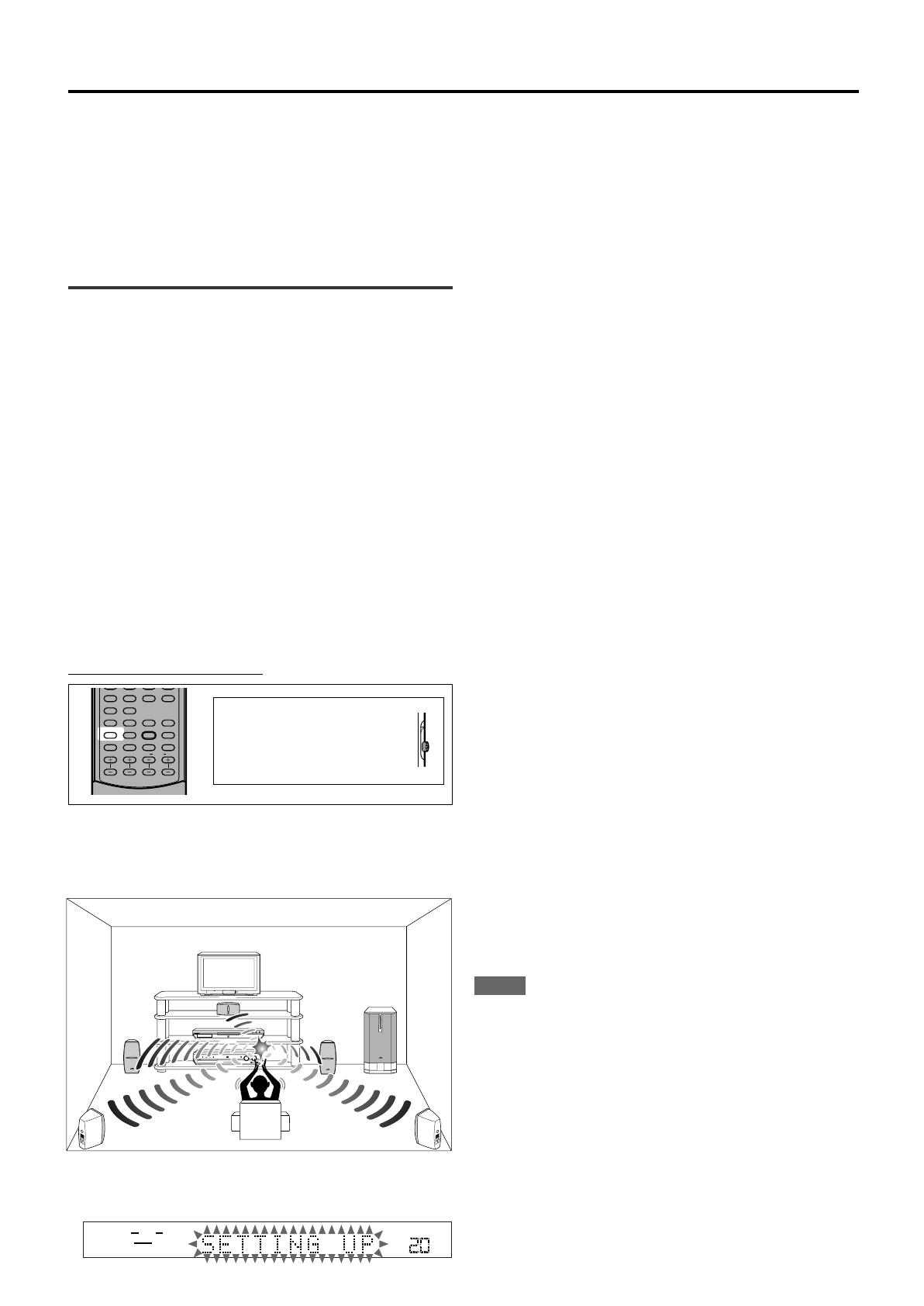
Take your position where you listen to the sound.
ANALOG
SUBWFR
LR
VOL
DIGITAL
SURROUND
DIGITAL
PRO LOGIC
RX-ES1 HOME CINEMA CONTROL CENTER
STANDBY / ON STANDBY
TV DIRECT SETTING ADJUST SURROUND
DVD MULTI DVD STB VCR TV FM / AM
SET / TUNER PRESET
SOURCE SELECTOR MASTER VOLUME
PHONES
/ MULTI JOG
DVD
AUDIO/TV
/VCR/DBS
ANGLE
REPEAT
DIMMER
SUBWFR CENTER L RSURR
BASS BOOST
A.POSITION
SMART S. SETUP
SLEEP CANCEL
SURROUND
ANALOG/DIGITAL
TV RETURN 100
+
INPUT
TONE
TEST EFFECT
DECODE
10
3D
0 +10
2
Press and hold SMART S. SETUP.
SETTING UP flashes on the display.
TO BE CONTINUED TO THE NEXT PAGE
15-20.RX-ES1SL[J]1 03.3.28, 7:08 PM15
16
Setting the speakers and subwoofer
information quicklyQuick Setup
Entering the use of the subwoofer, the number of the speakers, and
your room size, the center and surround speakers delay time is
automatically calculated.
When you change your speakers, register the information about the
speakers again.
You can also set the crossover frequency, the low frequency effect
attenuator and the dynamic range compression manually (see page 18).
On the front panel ONLY:
Before you start, remember...
There is a time limit in doing the following steps. If the setting is
canceled before you finish, start from step
1
again.
1
Press SETTING.
MULTI JOG now works for the setting operation.
2
Turn MULTI JOG until QUICK SETUP appears
on the display.
As you turn MULTI JOG, the indication changes as follow:
3
Press SET.
ENTER THE NUMBER OF SPEAKERS scrolls on the display.
Once you have selected QUICK SETUP, previously adjusted
speaker setting is cleared.
4
Turn MULTI JOG to select the number of the
speakers you have connected.
As you turn MULTI JOG, the indication changes as follow:
5 SPEAKERS*: Select when the front, center and surround
speakers are connected.
4 SPEAKERS: Select when the front and surround speakers
are connected.
3 SPEAKERS: Select when the front and center speakers
are connected.
* Initial setting
Each speaker size is registered appropriately according to the
number of the connected speakers. For details, see the list
Speaker size according to the number of speakers on the right.
5
Press SET.
ENTER USE OF SUBWOOFER scrolls on the display.
6
Turn MULTI JOG to select whether or not you
have connected a subwoofer.
As you turn MULTI JOG, the indication changes as follow:
* Initial setting
7
Press SET.
ENTER ROOM SIZE scrolls on the display.
8
Turn MULTI JOG to select the room size.
As you turn MULTI JOG, the indication changes as follow:
* Initial setting
The center and surround speakers delay time is registered
appropriately according to the room size. For details, see the list
STANDBY / ON STANDBY
DIMMER SETTING ADJUST SURROUND
DVD MULTI DVD DBS VCR TV FM / AM
SET / TUNER PRESET
SOURCE SELECTOR MASTER VOLUME
PHONES
/ MULTI JOG
ANALOG
SUBWFR
VOL
LR
5 SPEKAERS*
3 SPEAKERS
4 SPEAKERS
ANALOG
SUBWFR
VOL
LR
USE *
NO
ANALOG
SUBWFR
VOL
LR
SMALL*
MEDIUM
LARGE
ANALOG
SUBWFR
VOL
LR
SUBWFR
FRNT SP
LFE
DIGITAL IN
AUTO SR
DVD VIDEO
QUICK SETUP
(Back to the beginning)
CNTR SP
SURR DL
CROSS
CNTR DL
D.COMP
SURR SP
DBS VIDEO
Speaker settings
Speaker delay time according to room size below.
9
Press SET to finish the setting.
SETUP END appears for a while, then the indication of the
previously selected source appears on the display.
NOTES
The setting you have made is not registered until SETUP END
appears on the display.
Performing any operation other than volume and dimmer
adjustment cancels Quick Setup process.
When you want to change the speaker and subwoofer information
after Quick Setup, use Manual Setup (see page 17).
Speaker size according to the number of speakers
Number of Subwoofer Front Center Surround
speakers
3 NO LRG (large) SML (small) NO
3 USE (YES) SML (small) SML (small) NO
4 NO LRG (large) NO SML (small)
4 USE (YES) SML (small) NO SML (small)
5 NO LRG (large) SML (small) SML (small)
5 USE (YES) SML (small) SML (small) SML (small)
Speaker delay time according to room size
C
L
R
LS
RS
8 feet
(2.4 m)
5 feet
(1.5 m)
6 feet
(1.8 m)
7 feet
(2.1 m)
When selecting SMALL ROOM,
Center speaker delay time
is set to 1 msec.
Surround speakers delay time
is set to 3 msec.
15-20.RX-ES1SL[J]1 03.3.17, 3:19 PM16
17
Speaker settings
When selecting MEDIUM ROOM,
Center speaker delay time
is set to1 msec.
Surround speakers delay time
is set to 2 msec.
ANALOG
SUBWFR
VOL
LR
SUBWFR
FRNT SP
LFE
DIGITAL IN
AUTO SR
DVD VIDEO
QUICK SETUP
(Back to the beginning)
CNTR SP
SURR DL
CROSS
CNTR DL
D.COMP
SURR SP
DBS VIDEO
3
Turn MULTI JOG to select the appropriate setting
for the item selected in step
2
, then press SET.
Your setting is stored.
EX.: When selecting NO for SUBWFR.
4
If you would like to set other items, repeat steps
2
and
3
.
Setting the subwoofer information
SUBWFR (subwoofer)
Register whether you have connected a subwoofer or not.
YES*: Select when you have connected a subwoofer.
The subwoofer speaker indicator (
SUBWFR
) lights up
on the display (see page 14). You can adjust the
subwoofer output level (see page 21).
NO: Select when you have not connected or have
disconnected a subwoofer.
* Initial setting
Setting the speakers size
FRNT SP (front speakers), CNTR SP (center
speaker), SURR SP (surround speakers)
Register the sizes of all the connected speakers.
LRG (large): Select when the cone speaker size is larger than
4
3
/4 inches (12 cm).
SML (small)*: Select when the cone speaker size is smaller than
4
3
/4 inches (12 cm).
NO: Select when you have not connected a speaker. (Not
selectable for the front speakers.)
* Initial setting
NOTES
If you have selected SML (small) for the front speaker size, you
cannot select LRG (large) for the center and surround speaker
sizes.
If you have selected NO for the subwoofer setting (see above and
page 16), you can only select LRG (large) for the front speaker
size.
ANALOG
VOL
LR
C
L
R
LS
RS
8 feet
(2.4 m)
9 feet
(2.7 m)
7 feet
(2.1 m)
When selecting LARGE ROOM,
Center speaker delay time
is set to 0 msec.
Surround speakers delay time
is set to 0 msec.
C
L
R
LS
RS
10 feet
(3.0 m)
Setting the speakers and subwoofer
information manuallyManual Setup
You can set the following speakers and subwoofer information
manually as you prefer. When you change your speakers, register the
information again.
Subwoofer informationSUBWFR
Speaker sizeFRNT SP, CNTR SP, SURR SP
Speaker delay timeCNTR DL, SURR DL
Crossover frequencyCROSS
Low frequency effect attenuatorLFE
Dynamic range compressionD.COMP
Operating procedure
On the front panel ONLY:
Before you start, remember...
There is a time limit in doing the following steps. If the setting is
canceled before you finish, start from step
1
again.
1
Press SETTING.
MULTI JOG now works for the setting operation.
2
Turn MULTI JOG until the setting item you want
to set appears on the display, then press SET.
As you turn MULTI JOG, the indication changes as follow:
STANDBY / ON STANDBY
DIMMER SETTING ADJUST SURROUND
DVD MULTI DVD DBS VCR TV FM / AM
SET / TUNER PRESET
SOURCE SELECTOR MASTER VOLUME
PHONES
/ MULTI JOG
CONTINUED ON THE NEXT PAGE
15-20.RX-ES1SL[J]1 03.3.17, 3:19 PM17
18
Setting the speaker delay time
CNTR DL (center speaker delay),
SURR DL (surround speakers delay)
You can set the speaker delay time easily by using Smart Surround
Setup (see page 15) or Quick Setup (see page 16).
The distance from your listening point to the speakers is one of the
important element to obtain the best possible surround sound for the
Surround modes.
You need to set the delay time of the center and surround speakers
relative to the front speakers so that sounds through all the speakers
can reach you at the same time.
1 msec increase (or decrease) in delay time corresponds to 1 foot
(30 cm) increase (or decrease) in distance.
CNTR DL*: Set the delay time for the center speaker within a
range of 0 msec to 5 msec (in 1 msec intervals).
SURR DL*: Set the delay time for the surround speakers within a
range of 0 msec to 15 msec (in 1 msec intervals).
* 0ms is the initial setting.
Example: In this case,
set CNTR DL to 1ms and
set SURR DL to 2ms.
NOTE
If the center and/or surround speakers are not connected (see pages
16 and 17), you cannot set the speaker delay time for the center and/
or surround speakers.
Setting the crossover frequency—CROSS
Small speakers cannot reproduce the bass sounds efficiently. If you
use a small speaker in any position, this receiver automatically
reallocates the bass sound elements assigned to the small speaker to
the large speakers.
To use this function properly, set this crossover frequency level
according to the size of the small speaker connected.
If you have selected LRG (large) for all speakers (see page 17),
this function will not take effect.
80HZ: Select when the cone speaker unit built in the
speaker is about 4
3
/4 inches (12 cm).
100HZ: Select when the cone speaker unit built in the
speaker is about 3
15
/16 inches (10 cm).
120HZ: Select when the cone speaker unit built in the speaker
is about 3
3
/16 inches (8 cm).
150HZ*: Select when the cone speaker unit built in the speaker
is about 2
3
/8 inches (6 cm).
200HZ: Select when the cone speaker unit built in the
speaker is less than 2 inches (5 cm).
* Initial setting
NOTE
Crossover frequency is not valid for the HEADPHONE mode.
Setting the low frequency effect attenuator
—LFE
If the bass sound is distorted while playing back software encoded
with Dolby Digital or DTS, set the LFE level to eliminate distortion.
This function takes effect only when the LFE signals come in.
0dB*: Normally select this.
10dB: Select when the bass sound is distorted.
* Initial setting
Setting the dynamic range compression
—D.COMP
You can compress the dynamic range (difference between maximum
sound and minimum sound) of the reproduced sound. This is useful
when listening to surround sound at night.
This function takes effect only when playing back a source encoded
with Dolby Digital.
OFF: Select when you want to enjoy surround with its full
dynamic range. (No effect applied.)
MID*: Select when you want to reduce the dynamic range a
little.
MAX: Select when you want to apply the compression effect
fully. (Useful at night.)
* Initial setting
Speaker settings
Left front
speaker
Right front
speaker
Right surround
speaker
Center speaker
Left surround
speaker
9 feet
(2.7 m)
10 feet
(3.0 m)
8 feet
(2.4 m)
7 feet
(2.1 m)
15-20.RX-ES1SL[J]1 03.3.17, 3:19 PM18
  • Page 1 1
  • Page 2 2
  • Page 3 3
  • Page 4 4
  • Page 5 5
  • Page 6 6
  • Page 7 7
  • Page 8 8
  • Page 9 9
  • Page 10 10
  • Page 11 11
  • Page 12 12
  • Page 13 13
  • Page 14 14
  • Page 15 15
  • Page 16 16
  • Page 17 17
  • Page 18 18
  • Page 19 19
  • Page 20 20
  • Page 21 21
  • Page 22 22
  • Page 23 23
  • Page 24 24
  • Page 25 25
  • Page 26 26
  • Page 27 27
  • Page 28 28
  • Page 29 29
  • Page 30 30
  • Page 31 31
  • Page 32 32
  • Page 33 33
  • Page 34 34
  • Page 35 35
  • Page 36 36
  • Page 37 37
  • Page 38 38
  • Page 39 39
  • Page 40 40
  • Page 41 41
  • Page 42 42
  • Page 43 43
  • Page 44 44
  • Page 45 45
  • Page 46 46
  • Page 47 47
  • Page 48 48
  • Page 49 49
  • Page 50 50
  • Page 51 51
  • Page 52 52
  • Page 53 53
  • Page 54 54
  • Page 55 55
  • Page 56 56
  • Page 57 57
  • Page 58 58
  • Page 59 59
  • Page 60 60
  • Page 61 61
  • Page 62 62
  • Page 63 63
  • Page 64 64
  • Page 65 65
  • Page 66 66
  • Page 67 67
  • Page 68 68
  • Page 69 69
  • Page 70 70
  • Page 71 71
  • Page 72 72
  • Page 73 73
  • Page 74 74
  • Page 75 75
  • Page 76 76
  • Page 77 77
  • Page 78 78
  • Page 79 79
  • Page 80 80
  • Page 81 81
  • Page 82 82
  • Page 83 83
  • Page 84 84
  • Page 85 85
  • Page 86 86
  • Page 87 87
  • Page 88 88

JVC RX-ES1SL User manual

Category
AV receivers
Type
User manual

Ask a question and I''ll find the answer in the document

Finding information in a document is now easier with AI